Table of Contents
Advertisement
Advertisement
Table of Contents
Troubleshooting

Related Manuals for Furuno GS-100


Summary of Contents for Furuno GS-100
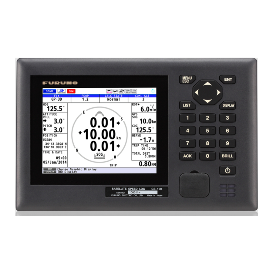
- Page 1 OPERATOR'S MANUAL SATELLITE SPEED LOG GS-100 Model www.furuno.com...
- Page 2 ・FURUNO Authorized Distributor/Dealer 9-52 Ashihara-cho, Nishinomiya, 662-8580, JAPAN A : MAY 2014 Printed in Japan All rights reserved. K : MAY 28, 2019 Pub. No. OME-72790-K ( YOTA ) GS-100 0 0 0 1 7 8 6 2 4 1 9...
- Page 3 How to discard a used battery Some FURUNO products have a battery(ies). To see if your product has a battery, see the chapter on Maintenance. If a battery is used, tape the + and - terminals of the battery before disposal to pre- vent fire, heat generation caused by short circuit.
- Page 4 Failure to turn off the equipment can this unit) should ever be relied cause fire or electrical shock. upon as the exclusive means for Contact a FURUNO agent for service. navigating your vessel. Use the correct fuse. The navigator is responsible for...
- Page 5 SAFETY INSTRUCTIONS Safety Instructions for the Installer WARNING CAUTION Ground the equipment to prevent Have a qualified serviceman do the electrical shock and mutual installation. interference. Only qualified personnel should work The mounting location for the units inside the equipment. must satisfy the following conditions: Turn off the power at the...
-
Page 6: Table Of Contents
TABLE OF CONTENTS FOREWORD ........................vii SYSTEM CONFIGURATIONS ..................ix EQUIPMENT LISTS ......................x OPERATIONAL OVERVIEW .................1-1 1.1 Controls........................1-1 1.2 How to Turn the Power On/Off................... 1-3 1.3 How to Adjust the Brilliance of the Display and Panel ..........1-4 1.4 Main Menu Overview ....................1-5 1.5 List Overview...................... - Page 7 5.2 Alert List........................5-5 5.3 Alert Log ........................5-6 5.4 How to Acknowledge Alerts..................5-6 5.5 Responsibility Transfer Alert..................5-7 BERTHING DISPLAY ....................6-1 6.1 Berthing Display for the GS-100.................6-1 6.2 Controls for the Display Unit DS-600................6-3 6.3 Various Settings ......................6-4 6.4 Display Range ......................6-7 6.4.1 How to select a range..................6-7...
- Page 8 TABLE OF CONTENTS 8.3.7 Offset menu....................8-19 8.3.8 Alert mode....................8-23 8.3.9 IP address ....................8-24 8.4 Connections and Adjustments with Optional Interface Unit IF-2503......8-24 8.5 Installation, Adjustment of Optional Display Unit DS-600 ........8-25 8.5.1 Installation of the display unit DS-600............8-25 8.5.2 Menu settings for DS-600 ................
-
Page 9: Foreword
• External USB memory capability (for maintenance) • Vessel speed for port and starboard at any position of the hull by built-in satellite compass • Optional DS-600 (display unit) can be connected to the GS-100 to add berthing support capa- bility •... - Page 10 GNSS 48505230** 2051590-01.** 2051591-01.** GS-1002 Boot 2051551-02.** 2051552-03.** DS-600 Starter 6652000-01.** Booter 6652001-02.** Main 6652002-02.** **: Minor change CE declaration With regards to CE declarations, please refer to our website (www.furuno.com) for further infor- mation about RoHS conformity declarations. viii...
-
Page 11: System Configurations
SYSTEM CONFIGURATIONS Basic configuration is shown with solid line. Antenna Unit GS-1001B Network Equipment, HUB, etc. MENU Nav Equipment, LIST DISPLAY IF-2503, etc. USB Flash Memory BRILL 24 VDC DS-600 (Sub Display) Display Unit GS-1002 Junction Box GS-1003 Rectifier PR-62 110/220 VAC 1ø, 50/60 Hz Environmental category... -
Page 12: Equipment Lists
EQUIPMENT LISTS Standard supply Name Type Code No. Remarks Antenna Unit GS-1001B-A Select For GNSS (GPS, GLONASS, Gal- ileo, QZSS) For cable 30/40/50m with armor GS-1001B-N For GNSS (GPS, GLONASS, Gal- ileo, QZSS) For cable 15/30m without armor Display Unit GS-1002 Junction Box GS-1003... - Page 13 EQUIPMENT LISTS Name Type Code No. Remarks Cable OP20-50 001-506-810 Replacement kit for GS- Conversion kit 1001 (MJ-A10SPF0015- xxxC) Contents - Waterproof relay box (JPBS 06) - 120 Ω Lead resistance (03S9939) - FRU-NMEA-PFF-060 - Vinyl tape (0.2X19X10000MM Black, 000-172-691-10) - Self-bonding tape (No.15, 000-174-646-10) Cable Assy.
- Page 14 EQUIPMENT LISTS This page is intentionally left blank.
-
Page 15: Operational Overview
OPERATIONAL OVERVIEW Controls Operation keys MENU MENU LIST DISPLAY LIST DISPLAY BRILL BRILL Function keys The keys are arranged according to the function. Function Menu screen Display mode MENU ESC • Closes the menu. Opens the menu. • Quits current operation. Confirms a selection. - Page 16 1. OPERATIONAL OVERVIEW Function Menu screen Display mode USB port For connection of USB flash memory. Key sound When you operate a key, a single beep sounds. If you do not need the key beep, de- activate the beep sound as follows (see section 1.4): 1.
-
Page 17: How To Turn The Power On/Off
1. OPERATIONAL OVERVIEW How to Turn the Power On/Off Press the key to turn the display unit on. The start-up screen appears for 30 sec- onds then the screen set at the [6 Device Mode] menu (see paragraph 8.3.2) appears. 2051552-03.xx Self test GNSS... -
Page 18: How To Adjust The Brilliance Of The Display And Panel
1. OPERATIONAL OVERVIEW How to Adjust the Brilliance of the Display and Panel 1. Press the BRILL key to show the following setting window. Switch the color mode between day mode and night mode. Long-press to restore the settings to default of day mode. 2. -
Page 19: Main Menu Overview
1. OPERATIONAL OVERVIEW Main Menu Overview 1. Press the MENU ESC key to open the main menu. GN 3D Triangles indicate additional menus. 2. Press the cursorpad ( ) to select a menu item then press the ENT key. You can also select a menu item by pressing the numeric keys. -
Page 20: List Overview
1. OPERATIONAL OVERVIEW List Overview The LIST key displays the active alert list, alert log list and device list, in the sequence shown below. GN 3D GN 3D Any display Active Alert GN 3D GN 3D GS - 1002 2051552- xx.xx 2051591- xx.xx Alert Log Device List... -
Page 21: Displays
DISPLAYS Display Modes The GS-100 has two main display modes. The SDME (Speed and Distance Measur- ing Equipment) mode measures speed and distance. The THD (Transmitting Heading Device) outputs heading data to external equipment. You can switch between the two display modes with the DISPLAY key. -
Page 22: How To Select The Background Color
2. DISPLAYS How to Select the Background Color You can select the background color to suit lighting conditions or environment (see section 1.3). 1. Press the MENU ESC key to open the main menu. 2. Select [1 Display] then [1 Background Color]. 3. - Page 23 2. DISPLAYS 3. Select [1 Window1]. Displays external input data for doppler SOG/COG. 4. Select [1 Roll/Pitch], [2 SDME] or 3 [Blank]. 5. Select the options for windows 2 to 5 as well. Window1 Window2 Window3 Window4 Window5 Atm: Atmospheric pressure Temp: Air temperature Note: The options [SDME], [Current], [Wind] and [Depth] require appropriate ex- ternal sensors.
- Page 24 2. DISPLAYS Calculation state Satellite (Start up, Normal, DR (Dead-Reckoning), number Spinner Stopped (HDG stopped), common See page rotates when HDOP: 2D to ANT1 SYS FAULT (System fault)) AP-8. PDOP: 3D the equipment and ANT2 is functioning normally. Status indication GN 3D Rate of turn : Starboard...
-
Page 25: Integrity Display
2. DISPLAYS 3-axis speed display The circle at the center of the display shows the own ship’s speed. Wind velocity* (Magenta) Current direction* ** (Blue) Drift angle* (Brown) Bow velocity Broadside speed at bow position*** Heading velocity Speed for heading Stern velocity Picture of ship... - Page 26 2. DISPLAYS GNSS The GNSS display shows the condition of satellite positioning system. Number, azi- muth and elevation angle of all satellites (if applicable) in view of your receiver appear. Satellites used for positioning (Satellite numbers used for positioning are displayed in white, or black if not used for positioning.) Satellite numbers* Elevation 60°...
- Page 27 2. DISPLAYS Graphs The graph displays show satellite angle and signal noise ratio used for positioning for the last six hours. Satellite angle Signal noise ratio...
- Page 28 2. DISPLAYS An alert (see chapter 5), which informs you to various types of errors, may appear on a graph display, with a red bar and triangle. Below is an an example of an alert on the signal noise ratio graph. A hollow triangle marks an alert that occurred within the past six hours.
-
Page 29: Settings
SETTINGS Display Menu 3.1.1 How to set the time for smoothing When the receiving condition is unfavorable, the GNSS fix may change randomly, even if the boat is dead in water. This change can be reduced by smoothing the raw GNSS fixes. -
Page 30: How To Use The "Cm/Sec" Display
3. SETTINGS 5. Select [2 Wind Speed]. 6. Select [1 True], [2 Theoretical] or [3 Relative]. [True]: The wind speed and angle minus movement of ship, reference to North. [Theoretical]: The wind speed and angle minus move- ment of ship, reference to ship’s bow. [Relative]: The speed and relative direction that the wind appears to blow with ship in motion, reference to ship’s bow. -
Page 31: Trip Menu
3. SETTINGS Trip Menu 3.2.1 How to calculate the trip distance 1. Press the MENU ESC key to open the main menu. 2. Select [2 Speed/Trip Setting] then [2 Trip]. 3. Select [1 Calculation]. 4. Select [1 Stop], [2 Start/Restart] or [3 Clear]. [Stop]: Stops the trip distance calculation. -
Page 32: System Menu
3. SETTINGS System Menu 3.3.1 How to change the user password You can set a four-character password to prevent unauthorized entry into certain menus. The default setting is no password. 1. Press the MENU ESC key to open the main menu. 2. -
Page 33: Sntp Setting
A demo mode, which shows internally generated navigation data, is provided to ac- quaint you with the features of the GS-100. You can set the demo mode as follows: 1. Press the MENU ESC key to open the main menu. - Page 34 3. SETTINGS then press one of keys from 0 to 9. [1. Direction]: Set the direction for translatory movement. [2. SOG]: Set the speed for translatory movement in kn. [3. Direction]: Select the direction for rotary motion from [CW] (clockwise) and [CCW] (counterclockwise).
-
Page 35: Gnss Menu
3. SETTINGS GNSS Menu 3.5.1 How to set the positioning condition Satellite elevation Note: This function is for a serviceman. You can set the minimum elevation of satellites to use to calculate the heading and position. Disable satellite Every GNSS satellite is broadcasting abnormal satellite number(s) in its Almanac, which contains general orbital data about all GNSS satellites. -
Page 36: Other Setting Menus For Antenna Unit
3. SETTINGS Other Setting Menus for Antenna Unit 3.6.1 How to reset the sensor You can reset the sensor (antenna unit) when experiencing antenna trouble. 1. Press the MENU ESC key to open the main menu. 2. Select [6 Sensor Setting] then [4 Other]. -
Page 37: How To Restart Heading Data Output After Restoration Of Heading Data
3. SETTINGS 3.6.4 How to restart heading data output after restoration of heading data Heading data can be output automatically or manually after heading data is restored. Note: If there is no heading data, the 3-axis speed data can not be output. 1. -
Page 38: Device Menu
3. SETTINGS 3.7.2 Device menu The Device List has the [Device] menu, which provides various information about the device selected and sets device instance and system instance. To display the [Device] menu, use the cursorpad to select the device then press the ENT key. GN 3D Menu item Function... -
Page 39: I/O Menu
3. SETTINGS I/O Menu Besides its fundamental function of displaying position, the GS-100 can also output various data to external equipment. Before outputting data to external equipment, first determine what data the external equipment requires. Output only necessary data to ensure data will be output correctly. -
Page 40: How To Set The Sentences To Output To The Ethernet
3. SETTINGS 8. Select [3 Sentence]. Note: Ask a serviceman, if [GGA], [GLL], [GNS], [RMC] or [XDR] is grayed out as shown in the below example. GN 3D 9. Press the cursorpad to select the sentence then press the ENT key. 10. -
Page 41: How To Select The Input Data
3. SETTINGS 3.8.3 How to select the input data 1. Press the MENU ESC key to open the main menu. 2. Select [5 I/O] then [6 Data Source Select]. 3. Select [1 HDG]. 4. Select the port for heading data. [1 Data1], [2 Data2], [4 Data4]: Use the heading data received from the equipment connected to the port 1 (or 2, 4). -
Page 42: Line Monitor Log
3. SETTINGS 8. Select [7 User Priority]. Note 1: The default priority order is Data1 > Data2 > Data4. Data 3 port is not available for serial input. Note 2: When the heading data is input from CAN, CAN has the top priority. 9. - Page 43 3. SETTINGS 3. Select [1 Data1] (or 2, 3, 4), [5 Ethernet] or [6 CAN]. The following is an example of the display for [Data1]. GN 3D $YCMTW,027.32,C$GPZDA,012614.00,01,11,2012,- $GPZDA,012613.00,01,11,2012,-09,00 45 09,00 42 $GPDTM,W84,,00.0000,N,00.0000,E,,W84 41 $YCMTW,027.32,C$GPZDA,012614.00,01,11,2012,- $GPGGA,012614.00,0844.7963,S,11512.6084,E,2,6,0.7,15,M,,M, 09,00 42 , 78 $YCMTW,027.32,C$GPZDA,012614.00,01,11,2012,- $GPVTG,258.0,T,256.5,M,0.1,N,0.2,K,D 2E 09,00 42...
-
Page 44: How To Set The Digit Number For Sentences
3. SETTINGS 3.8.5 How to set the digit number for sentences Set the number of figures to show after the decimal point for heading, speed (VTG, VBW), and roll, pitch. 1. Press the MENU ESC key to open the main menu. 2. -
Page 45: Notices
NOTICES There are two notice conditions which generate both audio and visual notices: Ship Speed and Trip. When the conditions of a notice are met, the buzzer sounds according to the notice sound setting and the icon related to the notice turns from gray to blue at the top right-hand corner of the display. -
Page 46: Trip Notice
4. NOTICES 2. Select [2 Speed/Trip Setting] then [1 Ship Speed]. 3. Select [2 In] or [3 Out]. The ship speed notice icon ( ) appears in gray at the top right-hand corner of the display. [In]: The notice alerts you when own ship’s speed is within the range set. -
Page 47: Alerts
Overview The GS-100 release alerts according to the alert mode selected at installation (Alert I/ F1, Alert I/F2, Legacy; see section 8.3.8). For full lists of the alerts for each alert mode, see "ALERT LIST" on page AP-27. - Page 48 5. ALERTS GN 3D The additional icon(s) apprear(s) here. Example 1: Warning GN 3D The additional icon(s) apprear(s) here. Example 2: Caution Alert category Priority Icon Visual indication Warning Circle • Acknowledged: Yellowish orange • Not acknowledged: Yellowish orange, flashing Caution Square Yellow...
- Page 49 5. ALERTS Text Priority System Fault Warning/B SDME SDME Fault Caution/B Alert I/F 2 Text Priority THD/SDME 430306 GNSS Core(2) Fault Caution/B GNSS Core(3) Fault Caution/B Too few Common Satellites Caution/B 3062 GNSS Core(2) Fault Warning/B GNSS Core(3) Fault Warning/B Too few Common Satellites Warning/B Antenna Unit Connection Lost...
- Page 50 5. ALERTS Table 1 Maximum error for transverse speed Z=10m Z=20m Z=30m Z=40m Z=50m Dead- Reckoning Transverse speed error time (s) (kn) -0.02828 -0.05656 -0.08483 -0.11311 -0.14139 -0.05656 -0.11311 -0.16967 -0.22622 -0.28278 -0.11311 -0.22622 -0.33933 -0.45244 -0.56555 -0.16967 -0.33933 -0.509 -0.67867 -0.84833 -0.19794...
-
Page 51: Alert List
5. ALERTS Alert List The alert list shows all currently violated alerts and state of acknowledgment. All un- acknowledged alerts are shown, even those whose reason for the alert has passed. 1. Press the MENU ESC key to open the main menu. 2. -
Page 52: Alert Log
5. ALERTS Alert Log The alert log shows the latest 50 alerts. When the log becomes full, the oldest entry is erased to make room for current alerts. 1. Press the MENU ESC key to open the main menu. 2. Select [3 Alert] then [4 Alert Log] to show the alert log. Priority GN 3D Alert name... -
Page 53: Responsibility Transfer Alert
5. ALERTS Responsibility Transfer Alert MSC302(87) requires the use of the “responsibility transfer alert,” which functions in the multiple sensor, multiple equipment installation. When one sensor or one equip- ment fails but does not disturb the system operation (other sensor or equipment is nor- mal), the CAM automatically sends the “responsibility transfer alert”... - Page 54 5. ALERTS This page is intentionally left blank.
-
Page 55: Berthing Display
Berthing Display for the GS-100 On the berthing display from the GS-100, the following four data are displayed as "– – –" because they are not input. • Doppler sonar SOG (STW) and COG •... - Page 56 “NSEW” (indicates the azimuth) are not shown. *2: ROT: Heading data is required only for [EXT HDG]. *3: These data can not be displayed in the GS-100. *4: Ground tracking: Green, Water tracking: Blue 3-axis speed data and NAV data Own ship marker The own ship marker indicates current position.
-
Page 57: Controls For The Display Unit Ds-600
6. BERTHING DISPLAY Controls for the Display Unit DS-600 MENU UNIT UNIT DISP BRILL TRKG MODE No use MENU DISP UNIT BRILL TRKG MODE Control Function Turn the power on and off. DISP • Select a display. • Close the menu and return to the last-used display. •... -
Page 58: Various Settings
6. BERTHING DISPLAY Various Settings Key beep A key beeps when it is pressed. You can turn this beep on or off. 1. Press the MENU ESC key to open the menu. 2. Select [Key Beep] then press the ENT key. 3. - Page 59 6. BERTHING DISPLAY How to set time Time You can select the source for time, set local time, and turn summer time indication (daylight savings time) on or off. 1. Press the MENU ESC key to open the menu. 2. Select [Ship's Time] then press the ENT key.
- Page 60 6. BERTHING DISPLAY Time format You can display time in UTC or ship's time (local time). 1. Press the MENU ESC key to open the menu. 2. Select [Scale Set Up] then press the ENT key. 3. Select [Mode] then press the ENT key. 4.
-
Page 61: Display Range
6. BERTHING DISPLAY Vector Time The tip of the vector line on the own ship marker shows the estimated position of your ship after the selected vector time elapses, using the current course and speed. You can adjust the length of the vector line to see estimated position at the end of the se- lected time interval. -
Page 62: How To Pre-Set Ranges
6. BERTHING DISPLAY 6.4.2 How to pre-set ranges The berthing display has a total of 11 ranges. Select the ranges to use, following the procedure shown below. A minimum of one range must be turned on. 1. Press the MENU ESC key to open the menu. 2. -
Page 63: How To Select The Type Of Track To Display
6. BERTHING DISPLAY Own ship marker Marker characteristics Own ship marker - One marker is added every 30 seconds. - Water tracking: Light blue - Ground tracking: Light green Reference position track Water tracking: Blue Ground tracking: Green Past track (solid line) Past track (marker) -
Page 64: How To Select The Past Track Format
6. BERTHING DISPLAY 6.5.3 How to select the past track format The past track can be shown with past track (ship) markers or solid line and past track markers. See the illustration at paragraph 6.5.1. 1. Press the MENU ESC key to open the menu. 2. -
Page 65: Berthing Line
Berthing lines, which can be used to assist in berthing operations, can be created and edited at the GS100. The saved lines can be sent to the DS-600 for display. A maxi- mum of 100 lines can be saved in the GS-100 and each line can have up to three points. - Page 66 6. BERTHING DISPLAY 3. Select [1 List]. GN 3D 4. With the cursor at the [New] position, press the ENT key. GN 3D 5. Enter the 1st position with the numeric keys. To change the coordinate, select "N" or "E" then press one of keys from 0 to 9. 6.
-
Page 67: How To Edit A Berthing Line
6. BERTHING DISPLAY 11. Select [9 Enter]. Note: It is necessary to enter a name and at least two positions in order to register a berthing line. GN 3D 12. Press the MENU ESC key to close the setting window. 6.7.2 How to edit a berthing line 1. -
Page 68: How To Send The Berthing Lines Data To Ds-600
6. BERTHING DISPLAY 6.7.4 How to send the berthing lines data to DS-600 To display the berthing lines on the display of the DS-600, do the following. Note: Turn on the DS-600 before doing the following procedures. 1. Press the MENU ESC key to open the main menu. 2. -
Page 69: Maintenance, Troubleshooting
MAINTENANCE, TROUBLE- SHOOTING NOTICE Do not apply paint, anti-corrosive sealant or contact spray to plastic parts or equipment coating. Those items contain products that can damage plastic parts and equipment coating. Maintenance Regular maintenance is important to maintain performance. Check the following points to help maintain performance. -
Page 70: Consumable Parts
7. MAINTENANCE, TROUBLESHOOTING after the replacement, contact your dealer for information. A wrong fuse can damage the equipment. Fuse GS-1003 Name Type Code No. Glass tube fuse FGMB-A 125V 3A PBF 000-157-481-10 Display unit DS-600 The fuse in the display unit DS-600 protects the unit from overcurrent. If you cannot turn on the power, have a technician check if the fuse inside the display unit has blown. -
Page 71: Troubleshooting
• Check the appropriate settings on the external equip- ment. • Check the connections: • Connect the TD-A of the GS-100 to the RD-A of the external equipment. • Connect the TD-B of the GS-100 to the RD-B of the external equipment. -
Page 72: Equipment Information
7. MAINTENANCE, TROUBLESHOOTING Equipment Information You can display the information of this equipment from the menu. 1. Press the MENU ESC key to open the main menu. 2. Select [4 Maintenance] then [1 Information]. 3. Select [1 Display Unit] or [2 Antenna Unit]. [1 Display Unit] [2 Antenna Unit] 4. -
Page 73: Self Test
7. MAINTENANCE, TROUBLESHOOTING Self Test The self test checks the ROM, RAM, input/output data, GNSS core, keyboard, LCD performance and sound. The user can do the tests to help the service technician in troubleshooting. Memory 1. Press the MENU ESC key to open the main menu. 2. - Page 74 7. MAINTENANCE, TROUBLESHOOTING LCD test The LCD test checks for proper display of colors. 1. Press the MENU ESC key to open the main menu. 2. Select [4 Maintenance] then [2 Self Test]. 3. Select [3 Test Pattern]. The operation instructions display opens. 4.
-
Page 75: Backup
6. Press the MENU ESC key to close the setting window. Backup The GS-100 can save user settings (current settings for display, unit, I/O, etc.) to a USB flash memory. You can load the saved settings after clearing the memory, for ex- ample. -
Page 76: Replacement Parts Settings
7. MAINTENANCE, TROUBLESHOOTING 3. Select [4 Maintenance] then [3 Backup]. 4. Select [1 Backup User Setting] or [2 Load User Setting]. [Backup User Setting]: Saves the cur- rent settings to USB. [Load User Setting]: Loads the saved settings from USB. This menu item re- quires the password. -
Page 77: Correction For The Replaced Sensor Board
7. MAINTENANCE, TROUBLESHOOTING 5. Select [1 Yes]. The message shown in the right figure appears. 6. Press the key to turn the power off. When you turn the power on next time, the operating time for a replacement part is reset to 0. 7.8.2 Correction for the replaced sensor board Set the rate gyro and acceleration through this menu only when installing the SUB IMU... - Page 78 7. MAINTENANCE, TROUBLESHOOTING This page is intentionally left blank. 7-10...
-
Page 79: Installation
INSTALLATION Mounting NOTICE Do not apply paint, anti-corrosive sealant or contact spray to coating or plastic parts of the equipment. Those items contain organic solvents that can damage coating and plastic parts, especially plastic connectors. 8.1.1 Display unit GS-1002 The display unit can be installed one of three ways, tabletop or flush mount (two types). - Page 80 8. INSTALLATION Flush mounting type S The optional flush mount kit type S is required. (Name: Flush Mount Kit (S-type), Type: OP20-40, Code No.: 001-243-890) Name Type Code No. Spring Washer M6 SUS304 000-158-855-10 Hexagonal Head Slot Bolt M6×12 SUS304 000-162-897-10 Wing Nut M4 YBSC2...
-
Page 81: Antenna Unit Gs-1001
The mounting location must satisfy the following four conditions. After selecting the lo- cation, determine the mounting height, following the procedure in the next topic. CONDITION 1: Locate the GS-100 sensor away from masts that might prevent reception of the GNSS signal Mount the sensor where the field of view against zenith is at least ±85°. - Page 82 8. INSTALLATION CONDITION 2: Locate the GS-100 higher than the top of radar and Inmarsat an- tennas*. GS-100 Radar antenna (open type) Higher than a radar antenna GS-100 Inmarsat antenna* Higher than a Inmarsat antenna* *: Other than a Inmarsat C CONDITION 3: Locate the GS-100 sensor away from communication antennas Separate the GS-100 as far as possible from communication antennas.
- Page 83 8. INSTALLATION Mounting procedure Note 1: The bird-repellent fixtures (optional supply) can be attached to the antenna cover to prevent birds from landing on the cover. If it is more convenient to attach the bird-repellent fixtures before securing the antenna unit to the mounting location, do step 6 below before fixing the antenna unit.
- Page 84 8. INSTALLATION Note: Fasten the double nuts as Note: Fasten the double nuts as shown in the figure to the shown in the figure to the right. Use spanners with a right. Use spanners with a length of approx. 200 mm. length of approx.
-
Page 85: Junction Box Gs-1003
8. INSTALLATION 8.1.3 Junction box GS-1003 Mounting considerations When selecting a mounting location, keep in mind the following points: • Locate the junction box away from heat sources because of heat that can build up inside the cabinet. • The vibration should be minimal. •... -
Page 86: Wiring
8. INSTALLATION Wiring Antenna Unit Junction box FRU-NMEA-NFF-R15/30 15/30 m (Without armor) 0.8 m 24 VDC ANT-DN18WAPVC-300/400/500 30/40/50 m (With armor) Cable assembly 80-580-0008 (0.3m) Ground terminal IV-1.25sq. Rear of Display Unit Ground terminal IV-1.25sq. DATA3 Junction box Junction box DATA1 DATA2 DATA4... -
Page 87: Junction Box
8. INSTALLATION 8.2.1 Junction box Connections Unfasten four screws to remove the cover, pass the cables through the clamps and attach the cables to respective connectors. The shield part of the cable (or drain wire) must lie in the clamp. The terminal opener is attached to the back of the cover. TB1: 24 VDC TB2: Display unit TB3: CAN cable... - Page 88 8. INSTALLATION DPYC-1.5 cable 50 mm 50 mm Armor Armor Attach crimp-on lug (M4). Attach crimp-on lug (M4). Vinyl tape Vinyl tape M12-05BFFM-060C Pass drain wire through Pass drain wire through shrink tubing (local supply). shrink tubing (local supply). 100 mm 100 mm Vinyl tape Vinyl tape...
-
Page 89: Display Unit
8. INSTALLATION FRU-NMEA-NFF-R15/30 (For pleasure or fishing vessel use) 140 mm 140 mm Unused signal wire Unused signal wire Pass drain wire through Pass drain wire through (Cut unused wire and (Cut unused wire and shrink tubing (local supply). shrink tubing (local supply). wrap it with vinyl tape). -
Page 90: Antenna Unit
8. INSTALLATION Fabrication TTYCS-1 Arbitrary length Arbitrary length 35 mm 35 mm 100 mm 100 mm 7 mm 7 mm Vinyl tape Vinyl tape Vinyl tape Vinyl tape Sheath Sheath Wind the shield. Wind the shield. 8.2.3 Antenna unit Connection of the cable assembly “80-580-0008” 1. -
Page 91: How To Connect The Cable Replacement Kit (Op20-50)
8. INSTALLATION 8.2.4 How to connect the Cable Replacement Kit (OP20-50) Use a waterproof relay box (JPBS06) to relay connection when connecting to the GS- 1001B with the MJ-A10SPF0015-150C/300C cable used in GS-1001. 1) Unfasten four washer head screws on the top of the waterproof relay box to re- move the cover. - Page 92 8. INSTALLATION 3) Fabricate the FRU-NMEA-PFF-060 cable as follows. 1) On the end of the side without the FRU connector, cut into the one end part of the FRU connector. Expose inner vinyl sheath by approx. 40 mm. Be careful not to damage inner shield and cores.
- Page 93 8. INSTALLATION 4) Connect the cables to the waterproof relay box. Connect the CAN cable (FRU-NMEA-PFF-060) included to the cable replace- ment kit and the cable for GS-1001 (MJ-A10SPF0015-150C/300C) to the inter- nal terminal box. MJ-A10SPF0015-150C/300C MJ-A10SPF0015-150C/300C FRU-NMEA-PFF-060 FRU-NMEA-PFF-060 Waterproof Relay Box (JPBS06) Waterproof Relay Box (JPBS06) 5) Fit the rubber bush, ring and cap, in that order.
-
Page 94: How To Secure And Waterproof The Cable Connections
8. INSTALLATION 8.2.5 How to secure and waterproof the cable connections Cable connection for the waterproof relay box, whether exposed to weather or other- wise, should be waterproofed and secured after making the connection. 1) Wrap the cap with several layers of self-bonding tape (supplied), to reduce the height difference between the cap and the box. -
Page 95: Adjustments
8. INSTALLATION Adjustments 8.3.1 Language The available languages are English and Japanese. 1. Press the MENU ESC key to open the main menu. 2. Select [7 System Setting] then [6 Language/ 3. Select [1 English]. 4. Press the MENU ESC key to close the main menu. 8.3.2 Device mode There are two display modes, [SDME] and [THD]. -
Page 96: Datum
8. INSTALLATION 3. Select [1 Unit of Distance] or [3 Unit of Depth] and go to step 4, or select [2 cm/sec Display] and go to paragraph 3.1.3. 4. Select the unit. The unit of the own ship’s speed changes, depend- Distance Depth ing on the selection at [1 Unit of Distance] as fol-... -
Page 97: Equipment Id
8. INSTALLATION Summer time Note: This menu is available when selecting [Local] in the [Local Time] menu. 1. Press the MENU ESC key to open the main menu. 2. Select [7 System Setting] then [1 System]. 3. Select [6 Summer Time]. 4. - Page 98 8. INSTALLATION 4. Enter the offset value with the numeric keys referring to as follows: 1) For example, to enter “+10.0°”, press the cursorpad (►) to move the cursor here. 2) Press the 0, 1, 0, 0 keys. When inputting positive number, “+”...
- Page 99 8. INSTALLATION Ship size and antenna position 1. Press the MENU ESC key to open the main menu. 2. Select [6 Sensor Setting] then [1 Offset]. 3. Select [5 ShipSize•ANT/CALC-SPD POS]. 1 : Set the width, length and height of your ship. Enter the values as correct as possible because these values influence the output sentence “POS”.
- Page 100 8. INSTALLATION SOG offset 1. Press the MENU ESC key to open the main menu. 2. Select [6 Sensor Setting] then [1 Offset]. 3. Select [6 SOG Offset]. 4. Enter the offset value with the numeric keys as follows: 1) For example, to enter “+10.0%”, press the cursorpad (►) to move the cursor here.
-
Page 101: Alert Mode
8. INSTALLATION 8.3.8 Alert mode 1. Press the MENU ESC key to open the main menu. 2. Select [3 Alert] then [2 Mode]. Note: This menu is for a serviceman. 3. Select [1 Alert I/F 1], [2 Alert I/F 2] or [3 Legacy]. For [1 Alert I/F 1] or [2 Alert I/F 2], go to step 6. -
Page 102: Ip Address
8. INSTALLATION 8.3.9 IP address Note: This function is for a serviceman. IP address for your equipment 1. Press the MENU ESC key to open the main menu. 2. Select [7 System Setting] then [2 Network]. 3. Select [1 Ethernet]. 4. -
Page 103: Installation, Adjustment Of Optional Display Unit Ds-600
8. INSTALLATION Installation, Adjustment of Optional Display Unit DS-600 The Display Unit GS-1002 can be connected with the optional DS-600. 8.5.1 Installation of the display unit DS-600 Mounting considerations The display unit DS-600 can be installed on a desktop, on the underside of a table, or flush mounted in a panel. - Page 104 8. INSTALLATION 5. Set a cosmetic cap to each fixing hole on the front panel. See "How to set the cos- metic caps and alarm lid assembly" on page 8-27. Desktop or table underside mount The display unit can be mounted on a desktop or on the underside of a table using the optional bracket.
-
Page 105: Menu Settings For Ds-600
8. INSTALLATION How to set the cosmetic caps and alarm lid assembly Set a cosmetic cap to each fixing hole on the front panel as shown in the illustration below. For the display unit to be used as a sub display, attach the alarm lid (supplied as ac- cessories) to the ALARM ACK key to prevent accidental operation of the key. - Page 106 Select [Main] or [Sub]. [Main], [Sub], [Satellite]* (For the display unit con- *: Sub display shared be- nected to the GS-1002, se- tween the GS-100 and the lect [Sub].) DS-60 [SIO Monitor] Monitor the serial signal input to the display units (main and sub).
- Page 107 8. INSTALLATION 3. Select [DISP1] or [DISP2] then press the ENT key. Full screen Two-way horizontal split screen Blank (no display)* *: Not available with DISP1. 4. Select the full screen then press the ENT key. 5. Select the orientation of the berthing display, [Berthing H Up] or [Berthing N Up], then press the ENT key.
-
Page 108: Adjustments For Gs-1002
4. Select [1 Yes]. The sen- sor restarts then the fol- GN 3D lowing screen appears. 5. Press the ENT key. The GS-100 starts calcula- GN 3D tion of trip time, trip dis- tance and average speed. 8-30... -
Page 109: Appendix 1 Menu Tree
APPENDIX 1 MENU TREE GS-100 Bold Italic : Default 1 Display Background Color (White , Black) Navigation Display Window1 (Roll/Pitch , SDME, Blank) Window2 (Position , Current, Blank) Window3 (Time&Date , Wind, Atm&Temp, Blank) Window4 (Heave , Depth, Blank) Window5 (Trip Time , Drift, Blank) Smoothing VTG (Open the setting window.) - Page 110 Backup Backup User Setting (Yes, No ) Load User Setting (Yes, No ) SW/Database Update* *: For serviceman. Chk the Available Software Display Unit: Application Display Unit: Boot Antenna Unit: Application Antenna Unit: GNSS Antenna Unit: OS Chk the New Data Table Datum Exchange* Display Unit...
- Page 111 Number of digits after decimal point VTG (1 , 2) VBW (1, 2 ) HDG (1 , 2) Roll, Pitch (1 , 2) Non-IMO Sentence Output* (Enable, Disable ) 6 Sensor Setting Offset* HDG Offset (Open the setting window.) *: For serviceman. Pitch Offset (Open the setting window.) Roll Offset (Open the setting window.) Position Offset (Open the setting window.)
- Page 112 Tech Menu* *: For serviceman. Inner Status (No , Yes) Legacy Sentence Input (Disable , Enable) VTG Speed Source (Sensor Raw , Corrected) VBW Speed Source (Sensor Raw, Corrected ) Trip calc (DS Mode , GS Mode) Device Mode (SDME , THD) Demo Moving Setting (Open the setting window.) Attitude Setting (Open the setting window.)
-
Page 113: Appendix 2 List Of Terms/Symbols
APPENDIX 2 LIST OF TERMS/SYM- BOLS The following table shows the terms and symbols used in the GS-100. Terms Terms Meaning Accelerometer Acknowledge Adjust, Adjustment Address ALARM Alarm Altitude ANGLE Angle Antenna April Atmosphere ATTITUDE Attitude August AUTO Automatic AVERAGE... - Page 114 APPENDIX 2 LIST OF TERMS/SYMBOLS Terms Meaning DGPS Differential GPS DISP Display DIST Distance Dilution Of Precision DOPPLER Doppler Dead Reckoning, Dead Reckoned Position DRIFT Drift DRMS Distance Root Mean Square Datum East EGNOS European Geo-Stationary Navigational Overlay System Enter Error Escape External...
- Page 115 APPENDIX 2 LIST OF TERMS/SYMBOLS Terms Meaning Maximum MSTR Master North Navigation Nautical Mile NORM Normal November Night October OFFSET Offset Omega Other Network Function Block Operating System Printed Circuit Board PDOP Positional Dilution Of Precision PITCH Pitch PORT Port/Portside POSITION, POSN, Position Pseudo-Random-Noise...
- Page 116 APPENDIX 2 LIST OF TERMS/SYMBOLS Terms Meaning Speed Through the Water Space Vehicle Software System True TCVR Transceiver TEMP Temperature Theoretical Wind Transmitting Heading Device TIME Ship’s Time, Time TOTAL Total TRIP Trip Transmit TXRX Transmit and Receive User Datagram Protocol Coordinated Universal Time, Universal Time Coordinated West WARNING...
- Page 117 APPENDIX 2 LIST OF TERMS/SYMBOLS Symbols Symbols Meaning Active unacknowledged warning Active acknowledged warning Active responsibility transferred warning Rectified unacknowledged warning Silenced warning Additional warning Additional caution Caution Ship speed notice (See section 4.2.) Trip notice (See section 4.3.) There is no GS-1001 in CAN network but SC-30 is. There is no GS-1001B in CAN network but SC-33 is.
-
Page 118: Appendix 3 Time Differences
APPENDIX 3 TIME DIFFERENCES AP-10... -
Page 119: Appendix 4 Geodetic Chart List
APPENDIX 4 GEODETIC CHART LIST : Alaska 001: WGS84 090: NORTH AMERICAN 1927 091: NORTH AMERICAN 1927 002: WGS72 : Bahamas (excl. San Salvador Is.) Mean Value (Japan, Korea & Okinawa) 003: TOKYO 092: NORTH AMERICAN 1927 : Bahamas, San Salvador Is. : Mean Value (CONUS) 004: NORTH AMERICAN 1927 093: NORTH AMERICAN 1927 (Cont’d) : Canada (incl. -
Page 120: Appendix 5 What Is Sbas
APPENDIX 5 WHAT IS SBAS? A satellite based augmentation system, or SBAS (Satellite Based Augmentation System), is an augmentation system that uses additional messages from satellite broadcasts to support regional and wide area augmentation. SBAS provides GPS signal corrections to SBAS users, for even bet- ter position accuracy, through the GPS error corrections that are widely broadcasted from the geo- stationary satellite. -
Page 121: Appendix 6 Digital Interface (Iec61162-1/2/450
All sentences except ALR and HBT output at the interval selected (00 - 90 s). Load requirements as listener Isolation: Photo coupler Input impedance: 470 ohms Max. voltage: ±15V Threshold: 3 mA (in case of connection of FURUNO device talker) AP-13... - Page 122 APPENDIX 6 DIGITAL INTERFACE (IEC61162-1/2/450) Data transmission Data is transmitted in serial asynchronous form in accordance with the standard referenced in IEC 61162-1 and IEC 61162-2. The first bit is a start bit and is followed by data bits. The following parameters are used: Baud rate: 4800 for IEC61162-1, 38400 for IEC-61162-2 Data bits: 8 (D7 = 0), parity none Stop bits: 1...
- Page 123 APPENDIX 6 DIGITAL INTERFACE (IEC61162-1/2/450) DATA 1 or 2 port (input) 3.3V_D 3.3V_D C18 0.1u PC400J00000F 3.3k R222 RD1-H (13A2) RD1-C (13A2) 1SS226_TE85L_F 3.3V_D 3.3V_D C19 0.1u PC400J00000F 3.3k R223 RD2-H (13C2) RD2-C (13C2) 1SS226_TE85L_F DATA 4 port 3.3V_D 5.1V_D 15V*15V / 330 = 0.68W Z_149_3P Rtotal = 330 /3 = 110...
- Page 124 APPENDIX 6 DIGITAL INTERFACE (IEC61162-1/2/450) DATA4 DATA2 NFM21CC470R1H3D NFM21CC470R1H3D MJ_A7SRMDC_R MJ_A6SRMDC_R FL37 FL41 TD2-A TD4-A (6A4) (5C6) TD4-A TD2-A FL38 FL42 TD2-B TD4-B (6A4) (5C6) TD4-B TD2-B FL43 FL39 RD2-H RD4-A (5A5) (6A4) RD2-H RD4-A FL44 FL40 RD4-B RD2-C (6A4) RD2-C (5B5) RD4-B...
- Page 125 APPENDIX 6 DIGITAL INTERFACE (IEC61162-1/2/450) Sentence description ACK-Acknowledge alarm $**ACK,xxx,*hh<CR><LF> 1. Local alarm number (identifier) ACM-Alert Command $**ACM,hhmmss.ss,aaa,x.x,x.x,c,a*hh<CR><LF> 3 4 5 6 1. Time (hh=00 to 23, mm=00 to 59, ss.ss=00.00 to 59.99), null 2. Manufacturer mnemonic code (3 digit alphanumeric code), null 3.
- Page 126 APPENDIX 6 DIGITAL INTERFACE (IEC61162-1/2/450) ALF-Alert sentence $**ALF,x,x,x,hhmmss.ss,a,a,a,aaa,x.x,x.x,x.x,x,c--c,*hh<CR><LF> 1 2 3 5 6 7 8 9 10 11 12 13 1. Total number of ALF sentences this message (1, 2) 2. Sentence number (1, 2) 3. Sequential message identifier (0 to 9) 4.
- Page 127 APPENDIX 6 DIGITAL INTERFACE (IEC61162-1/2/450) CUR-Water current layer–Multi-layer water current data $**CUR,A,x,x.x,x.x,x.x,a,x.x,x.x,x.x,a,a,*hh<CR><LF> 1 2 3 4 5 6 7 8 9 1011 1. Validity of data (A=Valid, V=Not valid) 2. Data set number (0 to 9) 3. Layer number (1 to 3) 4.
- Page 128 APPENDIX 6 DIGITAL INTERFACE (IEC61162-1/2/450) HRM-Heel angle, roll period and roll amplitude measurement device $**HRM,x.x,x.x,x.x,x.x,A x.x,x.x,hhmmss.ss,xx,xx*hh <CR><LF> 2 3 4 5 6 9 10 1. Actual heel angle, degrees 2. Roll period, seconds 3. Roll amplitude, port side, degrees 4. Roll amplitude, starboard side, degrees 5.
- Page 129 APPENDIX 6 DIGITAL INTERFACE (IEC61162-1/2/450) VBW-Dual ground/water speed $**VBW,x.x,x.x,x,x.x,x.x,x,x.x,x,x.x,x,*hh<CR><LF> 1 2 3 4 5 6 7 8 9 10 1. Longitudinal water speed, knots 2. Transverse water speed, knots 3. Status: water speed, A=data valid V=data invalid 4. Longitudinal ground speed, knots 5.
- Page 130 APPENDIX 6 DIGITAL INTERFACE (IEC61162-1/2/450) ZDA-Time and date $**ZDA,hhmmss.ss,xx,xx,xxxx,xx,xx,*hh<CR><LF> 1. UTC 2. Day 3. Month 4. Year (UTC) 5. Local zone, hours 6. Loca zone, minutes AP-22...
-
Page 131: Appendix 7 Parts List/Location
This equipment contains complex modules in which fault diagnosis and repair down to component level are not practical (IMO A.694(17)/8.3.1). Only some discrete components are used. FURUNO Electric Co., Ltd. Believes identifying these components is of no value for shipboard maintenance;... - Page 132 APPENDIX 7 PARTS LIST/LOCATION Parts location Antenna Unit GS-1001B 20P8222A 20P8222A 20P8234A GNSS_LNA GNSS_LNA MAIN Antenna element Antenna element Display Unit GS-1002 20P8218 20P8213 20P8209A CAN-FIL MAIN NL6448BC18-01F 20P8210 Display unit, cover opened AP-24...
- Page 133 APPENDIX 7 PARTS LIST/LOCATION Junction Box GS-1003 20P8221 Display Unit DS-600 26P0007 NL6448BC26-22F 02P6345 26P0006 MAIN AP-25...
-
Page 134: Appendix 8 Jis Cable Guide
EX: TTYCYSLA - 4 MPYC - 4 TTYCSLA-4 # of cores Designation type # of twisted pairs Designation type The following reference table lists gives the measurements of JIS cables commonly used with Furuno products: Cable Core Cable Core Diameter Type... -
Page 135: Appendix 9 Alert List
DR Mode Caution/B If this alert occurs fre- quently, contact your dealer. System Fault System Fault Warning/B Restart the GS-100. If the alert occurs again, contact your dealer. SDME SDME Fault SDME Fault Caution/B Restart the GS-100. If the alert occurs again, contact your dealer. - Page 136 HDOP thresh- old being permanently set to 4. No calculation of position Caution The signal from GPS Restart the GS-100. If Abbreviated messages: core is not received for the alert occurs again, No calculation of POSN three seconds. contact your dealer.
-
Page 137: Appendix 10Display For
APPENDIX 10 DISPLAY FOR DS-600 The display of data received from a GS-100 and DS-60 can be switched on the sub display DS-600. Installation The signals from GS-100 and DS-60 are directly output to the display unit DS-600. Connect the cables as shown in the figure below. - Page 138 Presetting The following settings must be set by a serviceman. • When using the DS-600 as the sub display for the GS-100, set [Operation] to [Sub] in the [Ser- vice] menu for DS-60 (see paragraph 8.5.2). • When using the DS-600 as the sub display for the GS-100 and DS-60, set [Operation] to [Sat- ellite] in the [Service] menu for DS-60 (see paragraph 8.5.2).
-
Page 139: Specifications
FURUNO GS-100 SPECIFICATIONS OF SATELLITE SPEED LOG GS-100 GENERAL Measurement range Speed Fore-aft: -60.0 to +60.0 kn, Port-stbd: -60.0 to +60.0 kn Trip distance 0.0 to 999999.9 NM or 0.00 to 999999.99 NM Heading 0.0 to 359.9° or 0.00 to 359.99°... - Page 140 IEC61162-450 transmission group MISC, SATD, NAVD OUT: Arbitrary (default: NAVD) Other Network Function (ONF) group of IEC61162-450 SNTP, HTTP, Furuno Management Protocol (FMP) Sentences ACK, ACM, ACN, CUR, DPT, HBT, HDG, HDT*, MWV, ROT, THS, VBW, VDR OUT: ALC, ALF, ALR, ARC, HBT, HDT*, HRM, POS, ROT, THS, VBW,...
- Page 141 FURUNO GS-100 Display unit (DS-600) -25°C to +55°C Relative humidity 95% or less at +40°C Degree of protection Antenna unit IP56 Display unit IP25, IPX0 (USB port cover opened) Junction box IP22 Display unit (DS-600) IP56 (front panel) Vibration IEC 60945 Ed.4...
- Page 151 13/Feb/2014 H.MAKI...
-
Page 155: Index
INDEX Numerics 3-axis speed display........2-5 IF-2503............ 8-24 Input data selection ......... 3-13 Integrity display ......... 2-5 Alert list ..........AP-27 IP address ..........8-24 Alert mode..........8-23 Alerts acknowledging ........5-6 Jis cable guide ........AP-26 list............5-5 log ............5-6 Key sound .......... - Page 156 INDEX Setting reset ..........3-8 Signal noise ratio ........2-7 Smoothing ..........3-1 SNTP setting ..........3-5 Speed test ..........8-30 System configurations........ix System instance........3-10 THD mode..........2-1 Time differences ........AP-10 Time format ..........8-18 Total distance..........3-3 Trip distance calculation ......3-3 Troubleshooting .........7-3 Unit selection ...........8-17 Wind angle ..........3-1 Wiring antenna unit ...........8-12...
Need help?
Do you have a question about the GS-100 and is the answer not in the manual?
Questions and answers