Table of Contents
Advertisement
Installation Manual
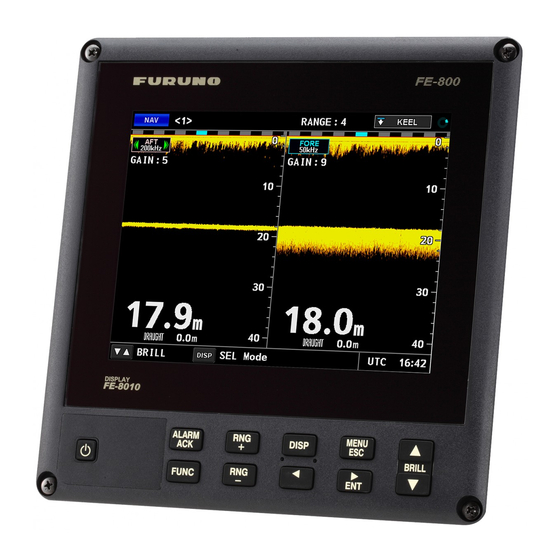
NAVIGATIONAL ECHO SOUNDER
FE-800
Model
SAFETY INSTRUCTIONS ................................................................................................ i
SYSTEM CONFIGURATION ........................................................................................... ii
EQUIPMENT LISTS........................................................................................................ iii
1. MOUNTING................................................................................................................. 1
1.1 Display Unit...........................................................................................................................1
1.2 Transceiver Unit....................................................................................................................5
1.3 Transducer............................................................................................................................5
1.4 Matching Box ........................................................................................................................7
1.5 Gate Valve GV-50B-6B, GV-200B-8B (option) .....................................................................8
2. WIRING....................................................................................................................... 9
2.1 Wiring....................................................................................................................................9
2.2 Cable Fabrication................................................................................................................10
2.3 Display Unit.........................................................................................................................13
2.4 Transceiver Unit..................................................................................................................13
2.5 Matching Box ......................................................................................................................16
2.6 Bridge Alert Management (BAM) Connection.....................................................................18
2.7 Junction Box (Option) .........................................................................................................18
3. ADJUSTMENTS ....................................................................................................... 19
3.1 Service Menu ......................................................................................................................19
3.2 How to Set the Time ...........................................................................................................20
3.3 How to Set the Frequency ..................................................................................................21
3.4 How to Set the Port.............................................................................................................21
3.5 How to Set the Ethernet......................................................................................................22
APPENDIX 1 JIS CABLE GUIDE .............................................................................AP-1
APPENDIX 2 DIGITAL INTERFACE ........................................................................AP-2
PACKING LISTS ......................................................................................................... A-1
OUTLINE DRAWINGS ................................................................................................ D-1
INTERCONNECTION DIAGRAM ................................................................................ S-1
www.furuno.com
All brand and product names are trademarks, registered trademarks or service marks of their respective holders.
Advertisement
Table of Contents

Related Manuals for Furuno FE-800


Summary of Contents for Furuno FE-800
-
Page 1: Table Of Contents
Installation Manual NAVIGATIONAL ECHO SOUNDER FE-800 Model SAFETY INSTRUCTIONS ....................i SYSTEM CONFIGURATION ................... ii EQUIPMENT LISTS......................iii 1. MOUNTING......................... 1 1.1 Display Unit...........................1 1.2 Transceiver Unit........................5 1.3 Transducer..........................5 1.4 Matching Box ........................7 1.5 Gate Valve GV-50B-6B, GV-200B-8B (option) ..............8 2. -
Page 2: Safety Instructions
The installer of the Transceiver unit equipment is solely responsible for the 1.50 m 0.95 m FE-8020 proper installation of the equipment. FURUNO will assume no responsibility for Matching box 0.80 m 0.50 m any damage associated with improper MB-502 installation. -
Page 3: System Configuration
SYSTEM CONFIGURATION Basic configuration is shown with solid line. DISPLAY UNIT FE-8010 Printer PP-505-FE Signal Power Power RD-20 or RD-50 TRANSCEIVER UNIT FE-8020 Contact signal RD-20 or RD-50 Network Equipment or PC Navigator Ship’s Mains 100-230 VAC BAM or IF-2503 JUNCTION JUNCTION JIS F8821-1MO... -
Page 4: Equipment Lists
EQUIPMENT LISTS Standard Supply Name Type Code No. Remarks Display Unit FE-8010 — Transceiver FE-8020 — Unit Matching MB-502 — Select For 50B-6B one. MB-504 — For 200B-8B Transducer 50B-6B — Select w/ 15/30/50 m cable one. 200B-8B — w/ 15/30/50 m cable Transducer TTF-5600 —... - Page 5 001-273-770 For display unit Spare Parts SP12-00801(BOX) 001-273-780 For transceiver unit Operator’s Manual FE-800 O/M *CD-ROM* — (CD-ROM) Interface Unit IF-2503 — Note: Windows is a registered trademark or trademark of the Microsoft Corporation of the USA and other countries.
-
Page 6: Mounting
MOUNTING NOTICE Do not apply paint, anti-corrosive sealant or contact spray to coating or plastic parts of the equipment. Those items contain organic solvents that can damage coating and plastic parts, especially plastic connectors. Display Unit 1.1.1 Installation consideration The display unit can be installed on a desktop or flush mounted in a console or panel. When selecting a mounting location, keep in mind the following points: •... -
Page 7: Flush Mounting
1. MOUNTING 1.1.3 Flush mounting For details, see the outline diagrams at the back of this manual. For octagonal cutout 1. Make an octagonal cutout in the mounting location as shown in the illustration be- low. 2. Make four pilot holes for self-tapping screws in the location indicated in the illus- tration below. - Page 8 1. MOUNTING For replacement of FE-680/FE-680T You can replace FE-680/FE-680T with FE-800, using the optional Front Fixing Panel kit OP12-1. Front Fixing Panel OP12-1 (code no.: 001-273-660) Name Type Code no. Remarks Binding head screw M5×12 SUS304 000-171-999-10 Front fixing panel...
- Page 9 1. MOUNTING 3. Make a four pilot holes for self-tapping screws (φ5×20) in the mounting location. 4. Fix the hanger to the mounting location with four self-tapping screws (φ5×20). 5. Insert a washer to each knob (right and left) and fix the washer to the display unit loosely.
-
Page 10: Transceiver Unit
1. MOUNTING Transceiver Unit 1.2.1 Installation considerations Keep in mind the following points when selecting a location. • Locate the transceiver unit away from heat sources because of heat that can build up inside the cabinet. • Locate the unit where shock and vibration are minimal. •... - Page 11 1. MOUNTING 1.3.1 Installation considerations To decide the location of the transducer, the following points should be taken into ac- count. • The most important matter is where the transducer is installed. The position should be free from aeration possibly occurring beneath the hull and also not affected by engine and propeller noise.
-
Page 12: Matching Box
1. MOUNTING ical damage. The conduit pipe should be fixed to the flange on the transducer tank. The pipe should be of such a length to clear the water level when the ship is fully loaded. The pipe end should be finished with filling compound. It is recom- mended to fill the pipe with sand between the transducer and the junction box (or matching box). -
Page 13: Gate Valve Gv-50B-6B, Gv-200B-8B (Option)
1. MOUNTING Gate Valve GV-50B-6B, GV-200B-8B (option) Assemble the gate valve as shown below. Refer to the drawing at the end of this man- ual. 1. Disassemble the gate valve as- Bolt sembled tentatively: spacer, Shaft Flange gasket1, gate valve, gasket 2, Shaft Bolt seachest cap and shaft assem-... -
Page 14: Wiring
WIRING Wiring The illustration below shows the cables to use to connect the units of the system. See the interconnection diagram at the back of the manual for details. TPYCSLA-1.5 Printer Display unit PP-505-FE FE-8010 DPYC-1.5 TTYCSLA-4 (Power) (Signal) DPYCYSLA-2.5 Junction box TTYCSLA-4 RD-20 or RD-50... -
Page 15: Cable Fabrication
2. WIRING Cable Fabrication TTYCSLA-1/TTYCSLA-4 <Side: Display unit> more than 50 Armor Core Core Sheath Sheath Drain wire Drain wire Vinyl tape Vinyl tape Vinyl tape Vinyl tape Clamp here. Clamp here. Wrap the drain wire around the sheath. <Side: Transceiver unit> Cable Core Core... - Page 16 2. WIRING TPYCSLA-1.5 <Side: Display unit> more than 50 Armor Core Core Sheath Sheath Drain wire Drain wire Vinyl tape Vinyl tape Vinyl tape Vinyl tape Clamp here. Clamp here. Wrap the drain wire around the sheath. DPYCYSLA-2.5 <Side: Transceiver unit> more than 50 Armor Sheath...
- Page 17 2. WIRING DTI-C5E350 VCV Note: Do not use an optical fiber cable. more than 50 Armor Cable jacket Cable jacket Inner vinyl sheath Inner vinyl sheath Outer vinyl Outer vinyl sheath sheath Modular plug Modular plug Vinyl tape Vinyl tape Clamp here.
-
Page 18: Display Unit
2. WIRING Display Unit Remove four screws to remove the rear cable cover. Remove the cable clamps to con- nect the cables. DISP board DISP board 12P1004 12P1004 Cable clamp Cable clamp From printer From printer From Transceiver unit From Transceiver unit Cable cover Cable cover From Transceiver unit... - Page 19 2. WIRING 2. Loosen four screws to open the fil- ter cover. Filter cover 3. Loosen or remove the cable entrance assembly as shown below. To connect CN8, CN10, CN12 and CN13, remove the cap spacers from the cable clamp. Remove two screws.
- Page 20 Battery Battery DIP SW Function 1: ON (Restore default settings.) Note: When FE-800 0: OFF (Default setting, for normal use) starts up with “ON”, The “FA” mark appears at the 1: ON (Start the transceiver unit indepen- top-left corner of the dently.)
-
Page 21: Matching Box
Transducer side - Cable gland Transceiver unit side - Two flat washers - Cable gland - Gasket - Three flat washers - Gasket The cable gland closest to the FURUNO logo is for the Transceiver unit. - Page 22 2. WIRING 3. Slide the cable gland, the gasket and the flat washers onto the cable as shown below. Side: Transceiver unit (DPYCYSLA-2.5) Side: Transducer (2RNCT-SB 2C×1.4) Flat washer Flat washer Flat washer Flat washer Cable gland Cable gland Cable gland Cable gland Gasket Gasket...
-
Page 23: Bridge Alert Management (Bam) Connection
2. WIRING Bridge Alert Management (BAM) Connection The power fail alarm can be output by connecting the Transceiver unit to the ship’s alert system or switchboard that can generate this type of alarm. Connect the TTYCSLA-1 cable between CN14 in the transceiver unit and the alert system of the ship referring to the schematic diagram at the end of this manual. -
Page 24: Adjustments
To take soundings properly the setting must be set to [ON]. Note: appears at the bottom-right corner of the screen when TX OFF FE-800 is turned on with the [OFF] setting. [B Volt] Set the voltage for B voltage. Select [Low] for normal use. -
Page 25: How To Set The Time
Accuracy] [Alert] [Alert Mode Select]: Select the alert mode among [Legacy], [Alert I/ F1] and [Alert I/F 2]. If IF-2503 is connected to FE-800, select [Lega- cy]. • [Legacy]: Use IIalr and IIals sentences. • [Alert I/F 1]: Use ALR and ACK sentences. -
Page 26: How To Set The Frequency
3. ADJUSTMENTS • [Time Difference]: If [Local] is selected in [Time], select [Auto] or [Manual] for setting method. • [Local Zone]: If [Manual] is selected in [Time Difference], set the time difference. Select [Internal] to use the internal clock. Select [Date] or [Time] to adjust and then set the value with the ... -
Page 27: How To Set The Ethernet
3. ADJUSTMENTS How to Set the Ethernet To set up the Ethernet for the LAN setting, select [I/O] → [Ethernet] on the [Service Menu], I / O Ethernet Port1 ► Navigation ► Port4 ► Management Profile ► Port Monitor ► Data Recorder ►... -
Page 28: Appendix 1 Jis Cable Guide
EX: TTYCYSLA - 4 MPYC - 4 TTYCSLA-4 Core Area (mm Designation type Designation type # of cores The following reference table lists gives the measurements of JIS cables commonly used with Furuno products: Cable Core Core Cable Diameter Diameter... -
Page 29: Appendix 2 Digital Interface
APPENDIX 2 DIGITAL INTERFACE I/O Sentences Note 1: ACK and ALR sentences are available when [Mode] in the [Alert] menu is set to [Alert I/F 1]. Note 2: ACM, ACN, ALC, ALF, ARC and HBT sentences are available when [Mode] in the [Alert] menu is set to [Alert I/F 2]. - Page 30 APPENDIX 2 DIGITAL INTERFACE ACK: Acknowledge alarm $**ACK,xxx *hh<CR><LF> 1. Unique alarm number (identifier) at alarm source GGA: Global positioning system (GPS) fix data $ ** GGA, hhmmss.ss, llll.ll, a, yyyyy.yy, a, x, xx, x.x, x.x, M, x.x, M, x.x, xxxx *hh <CR><LF> 5 6 7 9 10 11 12 13 1.
- Page 31 APPENDIX 2 DIGITAL INTERFACE RMC: Recommended minimum specific GNSS data $ ** RMC, hhmmss.ss A, llll.ll, a, yyyyy.yy, a, x.x, x.x, xxxxxx, x.x, a, a, a *hh <CR><LF> 6 7 8 9 10 11 12 13 1. UTC of position fix 2.
- Page 32 APPENDIX 2 DIGITAL INTERFACE ALF: Alert sentence $**ALF,x,x,x,hhmmss.ss,a,a,a,aaa,x.x,x.x,x.x,x,c--c *hh<CR><LF> 1 2 3 5 6 7 8 9 10 11 12 13 1. Total number of ALF sentences this message (1, 2) 2. Sentence number (1, 2) 3. Sequential message identifier (0 to 9) 4.
- Page 33 APPENDIX 2 DIGITAL INTERFACE DBS: Depth below surface $**DBS,x.x,f,x.x,M,x.x,F *hh<CR><LF> 1 2 3 4 5 6 1. Water depth 2. feet 3. Water depth 4. Meters 5. Water depth 6. Fathom DBT: Depth below transducer $ ** DBT, x.x, f, x.x, M, x.x, F *hh <CR><LF> 1 2 3 1, 2 Water depth, feet 3, 4 Water depth, m...
- Page 46 D-10...
- Page 47 D-11...
- Page 48 D-12...
- Page 49 D-13...
- Page 50 D-14...
- Page 52 ・FURUNO Authorized Distributor/Dealer 9-52 Ashihara-cho, Nishinomiya, 662-8580, JAPAN A : MAY 2014 Printed in Japan All rights reserved. B : JUL . 11, 2014 Pub. No. IME-23840-B ( AKMU ) FE-800 0 0 0 1 7 9 8 2 8 1 1...
Need help?
Do you have a question about the FE-800 and is the answer not in the manual?
Questions and answers