Taylor Horizon 8752 Operator's Manual
Pump soft serve freezers
Hide thumbs
Also See for Horizon 8752:
- Operator's manual (53 pages) ,
- Operating instructions manual (70 pages) ,
- Original operating instructions (58 pages)

Subscribe to Our Youtube Channel
Related Manuals for Taylor Horizon 8752


Summary of Contents for Taylor Horizon 8752
- Page 1 OPERATOR’S MANUAL Model 8752 and 8756 ® Horizon Pump Soft Serve Freezers Original Operating Instructions 11/17/09 (Original Publication) 028752HPM (Updated 8/12/2020)
- Page 2 Note: Only instructions originating from the factory or its authorized translation representative(s) are considered to be the original set of instructions. © November, 2009 Taylor Company (Updated 8/12/2020) 028752HPM Any unauthorized reproduction, disclosure, or distribution of copies by any person of any portion of this work may be...
-
Page 3: Table Of Contents
Table of Contents Section 1: To the Installer Installer Safety ......................1-1 Site Preparation ......................1-1 Air-Cooled Machines....................1-2 Water Connections......................1-2 Electrical Connections....................1-2 Beater Rotation ......................1-3 Refrigerant ........................1-3 Section 2: To the Operator Compressor Warranty Disclaimer ................2-2 Section 3: Safety Section 4: Operator Parts Identification Model 8752 .........................4-1 8752 Beater Door Assembly ..................4-3 Model 8756 .........................4-4... - Page 4 Table of Contents Section 7: Operator Checklist During Cleaning and Sanitizing...................7-1 Troubleshooting Bacterial Count.................7-1 Regular Maintenance Checks ..................7-1 ® The Horizon Pump ....................7-2 Winter Storage ......................7-2 Section 8: Troubleshooting Guide Section 9: Parts Replacement Schedule Section 10: Limited Warranty on Machines Section 11: Limited Warranty on Parts 028752HPM...
-
Page 5: Section 1: To The Installer
Taylor machines. operate indoors, under normal ambient temperatures of • Only Taylor service personnel should perform 70°F to 75°F (21°C to 24°C). The freezer has installation, maintenance, and repairs on Taylor successfully performed in high ambient temperatures of machines. -
Page 6: Air-Cooled Machines
TO THE INSTALLER Electrical Connections any damage to your Taylor distributor. Air-Cooled Machines Important! Do not obstruct air intake and discharge IMPORTANT! In the United States, this openings: machine is intended to be installed in accordance with the National Electrical Code (NEC), ANSI/NFPA 701987. -
Page 7: Beater Rotation
It is recommended that beater rotation adjustment be GFI, installed by the authorized personnel to performed by a Taylor service technician. local codes. Refrigerant •... - Page 8 NOTICE! Taylor reminds technicians to be aware of and in compliance with local government laws regarding refrigerant recovery, recycling, and reclaiming systems. For information regarding applicable local laws, please contact your local authorized Taylor distributor. To the Installer Models 8752 and 8756 with Horizon® Pump...
-
Page 9: Section 2: To The Operator
In the event you should require technical assistance, please contact your local authorized Taylor distributor. Note: Your Taylor warranty is valid only if the parts are authorized Taylor parts, purchased from the local authorized Taylor distributor, and only if all required service work is provided by an authorized Taylor service technician. -
Page 10: Compressor Warranty Disclaimer
It should also be noted that Taylor does not warrant the refrigerant used in its machines. For example, if the refrigerant is lost during the course of ordinary service to... -
Page 11: Section 3: Safety
Safety Section 3 We at Taylor Company are concerned about the safety of the operator when he or she comes in contact with the freezer and its parts. Taylor has gone to extreme efforts to design and manufacture built-in safety features to IMPORTANT! An equipotential grounding lug is protect both you and the service technician. - Page 12 CAUTION! This machine must be placed on a Failure to follow these instructions may result in level surface. Extreme care should be taken when electrocution. Contact your local authorized Taylor moving for any reason. Two or more persons are distributor for service.
- Page 13 SAFETY rear of the machine against the wall to prevent the recirculation of warm air. Failure to follow this instruction may cause poor freezer performance and damage to the machine. For Indoor Use Only: This machine is designed to operate indoors, under normal ambient temperatures of 70°F to 75°F (21°C to 24°C).
- Page 14 SAFETY Notes: Safety Models 8752 and 8756 with Horizon® Pump...
-
Page 15: Section 4: Operator Parts Identification
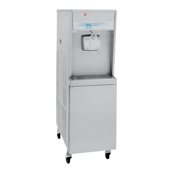
Operator Parts Identification Section 4 Model 8752 Figure 4-1 Operator Parts Identification Models 8752 and 8756 with Horizon® Pump... - Page 16 OPERATOR PARTS IDENTIFICATION Model 8752 Parts Identification Item Description Part No. Item Description Part No. Panel A.-Front X22997 Tank-Mix-15 Gallon 020275 Stud-Nose Cone 022822 Funnel-Mix 036637 Bolt-Carriage 1/4-20 X 3/4 012347 Cover A.-Mix Tank-Single X38726 Panel A.-Lower Side X23956SSP Tray-Drip 16-7/8L X 5-1/8 020157 Panel-Upper Side L.
-
Page 17: 8752 Beater Door Assembly
OPERATOR PARTS IDENTIFICATION 8752 Beater Door Assembly Figure 4-2 Item Description Part No. Item Description Part No Seal−Drive Shaft 032560 Handle−Adjustable 028804 Shaft−Beater 032564 Screw−Adjustment 055092 Beater A.−3.4 qt−1 Pin X46231 O-ring−1/4 OD X .070W 50 015872 Blade−Scraper−Plastic 084350 Nut−Jam 029639−BLK Kit A.−Beater−Front Shoe X50350... -
Page 18: Model 8756
OPERATOR PARTS IDENTIFICATION Model 8756 13 13a Figure 4-3 Operator Parts Identification Models 8752 and 8756 with Horizon® Pump... - Page 19 OPERATOR PARTS IDENTIFICATION Model 8756 Parts Identification Item Description Part No. Item Description Part No. Hood 048526 Funnel−Mix 036637 Panel−Upper Rear 022015 Cover−Mix Tank 024590 Trim A.−Side X22424 Cover−Mix Storage Right 037139 Panel−Upper Side Right 028600 Cover−Mix Storage Left 037138 Pan−Drip 027504 Boot−Mix Cover...
-
Page 20: 8756 Beater Door Assembly
OPERATOR PARTS IDENTIFICATION 8756 Beater Door Assembly Figure 4-4 ITEM DESCRIPTION PART NO. ITEM DESCRIPTION PART NO. Beater A.−3.4qt−1 Pin X46231 Seal−Draw Valve 034698 Shaft−Beater 032564 Nut−Stud−Long 034382 Seal−Drive Shaft 032560 Nut−Stud−Short 034383 Blade−Scraper−Plastic 084350 Plug−Prime 028805 Kit A.−Beater−Front Shoe X50350 O-ring−3/8 OD X .070W 016137... -
Page 21: Horizon ® Mix Delivery Pump
OPERATOR PARTS IDENTIFICATION ® Horizon Mix Delivery Pump 16 17 Figure 4-5 Item Description Part No. Item Description Part No. Cap-Valve-Check-Peris. 051946 Fitting-Pump Tube 066482 Pin-Retaining 1/4 OD x 2” L 042306 O-ring 3/4 OD x .103 W 015835 Poppet-Rubber-Black 022473 Poppet-Rubber-Black 022473... -
Page 22: Accessories
OPERATOR PARTS IDENTIFICATION Accessories Apply the appropriate Taylor approved food safe lubricant. Figure 4-6 Item Description Part No. Item Description Part No. Brush−Mix Pump Body 023316 ® 065293 Sanitizer−Stera Sheen Brush−Pressure Switch 027647 Pail−10 qt. 013163 Brush−Feed Tube 021101 Kit A.−Tune Up (8752) X49463−37... -
Page 23: Section 5: User Interface
= MIX LOW To better communicate in the international arena, the words on many of our operator switches and buttons have symbols to indicate their functions. Your Taylor = MIX OUT machine is designed with these international symbols. = AUTO... -
Page 24: Softech™ Control Operation
USER INTERFACE Softech™ Control Operation Power Switch When placed in the on position, the power switch allows MIX REF Softech™ control panel operation. When the MIX REF button is pressed, the light comes on, Indicator Lights indicating the mix cabinet refrigeration system is operating. -
Page 25: Adjustable Draw Handle
USER INTERFACE Airflow Adjustment AUTO Note: Adjust airflow prior to priming the machine with When the AUTO button is pressed, the light will turn on, mix. indicating the main refrigeration system has been 1. Open the prime plug. activated. In Auto mode, the WASH or STANDBY button functions are automatically canceled. - Page 26 USER INTERFACE Notes: User Interface Models 8752 and 8756 with Horizon® Pump...
-
Page 27: Section 6: Operating Procedures
These models, for all practical purposes of operation, are the same. Apply the appropriate Taylor approved food safe lubricant. The size of the freezing cylinder(s) is 3.4 qt. (3.2 L). Model 8752 has one freezing cylinder, and Model 8756 has two freezing cylinders. - Page 28 OPERATING PROCEDURES 4. Holding the rear blade on the beater, slide it into the 11529 freezing cylinder half way. Install the front scraper blade over the front holding pin. 11531 Figure 6-3 If the blades are in good condition, place the rear scraper blade over the rear holding pin on the beater.
- Page 29 Figure 6-10 14. Install the draw valve(s). Slide the two O-rings into Apply the appropriate Taylor approved food safe lubricant. the grooves on the draw valve(s). Model 8756 Only: Slide the O-ring and the H-ring into the grooves on the center draw valve.
- Page 30 Slide the Apply the appropriate long pivot pin through the right and middle draw Taylor approved food safe lubricant. handles. Secure the left draw handle with the short pivot pin. The draw handles have a color identifier for vanilla, twist, and chocolate.
-
Page 31: Horizon® Pump Assembly
Note: Do not place the diaphragm in the pressure 10176i switch cap. 15037 Apply the appropriate Taylor approved food safe lubricant. Apply the appropriate Taylor approved food safe lubricant. Figure 6-16 21. Install the front drip tray and the splash shield Figure 6-18 beneath the door spout(s). - Page 32 15161 15075 Apply the appropriate Taylor approved food safe lubricant. Figure 6-20 Figure 6-23 5. Place the rubber poppet in one end of the spring. Do not lubricate the rubber poppet.
- Page 33 15175 15178 Apply the appropriate Taylor approved food safe lubricant. Figure 6-29 Figure 6-26 14. Slide the pressure relief valve onto the main pump 11. Place an O-ring on the valve inlet fitting and lightly assembly.
- Page 34 OPERATING PROCEDURES 15. Secure the pressure relief assembly by installing the 17. Install the pressure line. Attach the quick disconnect retaining pin into the rear retaining pin plate. fitting of the pressure line to the other fitting on the mix inlet tube, just above the flare line. Allow the 15180 other end to hang free.
-
Page 35: Sanitizing
OPERATING PROCEDURES 19. Attach the open end of the mix suction tube to the 3. Press the PUMP button. An indicator will light, ® indicating the Horizon ® pump is operating. This pressure relief inlet fitting of the Horizon pump. action will cause the sanitizing solution to be pumped 15173 through the pump and out through the pressure line. -
Page 36: Airflow Adjustment
OPERATING PROCEDURES 5. Place an empty pail beneath the door spout and raise 7. After 5 minutes, open the prime plug. Press the the prime plug. PUMP button. Pull the draw handle down and draw off the remaining sanitizer. 10160 10168 Figure 6-39 Figure 6-41... -
Page 37: Priming
OPERATING PROCEDURES 4. Adjust the airflow to the desired setting. The flow rate 4. Place the free end of the suction line down in the mix is factory set at 1.0 to 1.4 cfm. tank. 17043 15181 Figure 6-43 Figure 6-45 5. -
Page 38: Closing Procedure
OPERATING PROCEDURES 8. Press the PUMP button. This will allow the mix to be 11. Press the AUTO button. The MIX REF light will come pumped through the freezing cylinder and force out on, to indicate the mix refrigeration system is any remaining sanitizer. -
Page 39: Draining Product From The Freezing Cylinder
OPERATING PROCEDURES Draining Product from the Freezing 2. Disconnect the pressure line from the check valve Cylinder and place it in the pail of water. 1. Press the AUTO and MIX REF buttons to cancel 15183 freezer operation. 2. Open the mix cabinet door and remove the mix storage cover(s), mix tank cover(s), mix tank(s), and mix probe(s). -
Page 40: Cleaning
OPERATING PROCEDURES Cleaning 5. Place an empty pail beneath the door spout. Raise the prime plug and press the WASH and PUMP 1. Prepare a pail of approved 100 ppm cleaning solution buttons. (for example, 2 gal. [7.6 L] of Stera-Sheen ® ). 10160 Note: Use warm water and follow the manufacturer’s specifications. -
Page 41: Disassembly
OPERATING PROCEDURES Brush-Cleaning 6. When a steady stream of solution is flowing from the prime plug hole in the bottom of the freezer door, pull 1. Prepare a sink with an approved cleaning solution down the draw handle and draw off the remaining (for example, Stera-Sheen ®... - Page 42 OPERATING PROCEDURES 8. Using the long, flexible brush and the cleaning 9. Remove the rear drip pan from the side panel and solution, clean the mix inlet tube(s) located in the mix take it to the sink for cleaning. cabinet. Thoroughly clean the tube(s) all the way up Note: If the rear drip pan is filled with an excessive to the freezing cylinder.
-
Page 43: Section 7: Operator Checklist
Operator Checklist Section 7 During Cleaning and Sanitizing On a designated day of the week, run the mix as low as feasible and discard after closing. This will Cleaning and sanitizing schedules are governed by break the rerun cycle and reduce the possibility of federal, state, or local regulatory agencies, and must be high bacteria and coliform counts. -
Page 44: The Horizon ® Pump
Deteriorated or cracked water lines precautions, particularly if the building is subject to should be replaced only by a Taylor mechanic. freezing conditions. Your machine is equipped with an auxiliary Disconnect the freezer from the main power source to refrigeration system. -
Page 45: Section 8: Troubleshooting Guide
Troubleshooting Guide Section 8 Table 8-1 Page Problem Probable Cause Remedy Ref. 1. No product is being a. Low on mix. The MIX OUT light is a. Add mix to the mix tank and press the dispensed. AUTO button. b. The power switch is in the off b. - Page 46 TROUBLESHOOTING GUIDE Page Problem Probable Cause Remedy Ref. 3. Product is too stiff. a. Viscosity control is set too cold. a. Contact a service technician. - - - b. Insufficient mix in the freezing b. See problem 2. - - - cylinder c.
- Page 47 TROUBLESHOOTING GUIDE Page Problem Probable Cause Remedy Ref. 8. Excessive mix leakage into a. Worn or missing driveshaft seal a. Install or replace the seal. 6-1/9-1 the rear drip pan. b. Improper lubrication of the b. Lubricate properly. driveshaft c. Worn rear shell bearing c.
- Page 48 TROUBLESHOOTING GUIDE Notes: Troubleshooting Guide Models 8752 and 8756 with Horizon® Pump...
- Page 49 Section 9 Parts Replacement Schedule Table 9-1 Every 4 Part Description Every 3 Months Every 6 Months Every 6 Months Annually Months Scraper Blades Driveshaft Seal Freezer Door Gasket Front Bearing Beater Shoes Draw Valve O-ring Prime Plug O-ring Pivot Pin O-ring Design Cap ®...
- Page 50 PARTS REPLACEMENT SCHEDULE Notes: Parts Replacement Schedule Models 8752 and 8756 with Horizon® Pump...
-
Page 51: Section 10: Limited Warranty On Machines
LIMITED WARRANTY Taylor warrants the Product against failure due to defect in materials or workmanship under normal use and service as follows. All warranty periods begin on the date of original Product installation. If a part fails due to defect during the applicable warranty period, Taylor, through an authorized Taylor distributor or service agency, will provide a new or remanufactured part, at Taylor’s option, to replace the failed defective part at no charge for the part. - Page 52 LEGAL REMEDIES The owner must notify Taylor in writing by certified or registered letter to the following address, of any defect or complaint with the Product, stating the defect or complaint and a specific request for repair, replacement, or other correction of the Product under warranty, mailed at least thirty (30) days before pursuing any legal rights or remedies.
-
Page 53: Section 11: Limited Warranty On Parts
Taylor warrants the Parts against failure due to defect in materials or workmanship under normal use and service as follows. All warranty periods begin on the date of original installation of the Part in the Taylor machine. If a Part fails due to defect during the applicable warranty period, Taylor, through an authorized Taylor distributor or service agency, will provide a new or remanufactured Part, at Taylor’s option, to replace the failed defective Part at no charge for the Part. - Page 54 Parts or the machines in which they are installed repaired or altered in any way so as to, in the judgment of Taylor, adversely affect performance, or normal wear or deterioration.
- Page 55 LEGAL REMEDIES The owner must notify Taylor in writing, by certified or registered letter to the following address, of any defect or complaint with the Part, stating the defect or complaint and a specific request for repair, replacement, or other correction of the Part under warranty, mailed at least thirty (30) days before pursuing any legal rights or remedies.
- Page 56 LIMITED WARRANTY ON PARTS Notes: 11-4 Limited Warranty on Parts Models 8752 and 8756 with Horizon® Pump...
Need help?
Do you have a question about the Horizon 8752 and is the answer not in the manual?
Questions and answers