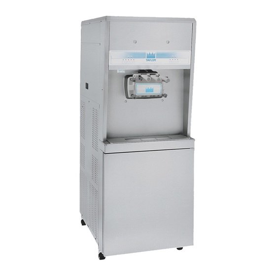
Taylor 8756 Operator's Manual
Single stage pump soft serve freezer
Hide thumbs
Also See for 8756:
- Operator's manual (58 pages) ,
- Operating instructions manual (70 pages) ,
- Original operating instructions (58 pages)

Related Manuals for Taylor 8756


Summary of Contents for Taylor 8756
- Page 1 OPERATOR'S MANUAL Model 8756 Single Stage Pump Soft Serve Freezer Original Operating Instructions 069071-M 11/15/10 (Original Publication) (Updated 7/1/16)
- Page 2 Phase Maximum Fuse Size: Minimum Wire Ampacity: E 2010 Taylor Company 069071-M Any unauthorized reproduction, disclosure, or distribution of copies by any person of any portion of this work may be a violation of Copyright Law of the United States of America and other countries, could result in the awarding of Statutory Damages of up to $250,000 (17 USC 504) for infringement, and may result in further civil and criminal penalties.
-
Page 3: Table Of Contents
............. . Table of Contents Model 8756... - Page 4 Note: Only instructions originating from the factory or its authorized translation representative(s) are considered to be the original set of instructions. E 2010 Taylor Company (Original Publication) (Updated April, 2015) 069071-M...
-
Page 5: To The Installer
PPE is available and worn Uncrate the unit and inspect it for damage. Report when required during installation and any damage to your Taylor Distributor. service. Authorized service personnel must remove This piece of equipment is made in the USA and has all metal jewelry, rings, and watches before USA sizes of hardware. -
Page 6: Water Connections (Water Cooled Units Only)
Please contact your local authorities. periods or during initial installation, shall have protective devices such as a GFI, to protect against the leakage of current, FOLLOW YOUR LOCAL ELECTRICAL CODES! installed by the authorized personnel to the local codes. To the Installer Model 8756... -
Page 7: Beater Rotation
The following procedures must be performed by an authorized Taylor service Taylor reminds technicians to be cautious of technician. government laws regarding refrigerant recovery, recycling, and reclaiming systems. If you have any... -
Page 8: To The Operator
In the event you should require technical assistance, It should also be noted that Taylor does not warrant please contact your local authorized Taylor the refrigerant used in its equipment. For example, if Distributor. -
Page 9: Safety
We, at Taylor Company, are concerned about the safety of the operator at all times when they are coming in contact with the unit and its parts. Taylor makes every effort to design and manufacture All repairs should be performed by an built-in safety features to protect both operators and authorized Taylor service technician. - Page 10 78 dB(A) when measured at a distance of safely move this unit. Failure to comply may result in 1.0 meter from the surface of the unit and at a personal injury or damage to the unit. height of 1.6 meters from the floor. 131220 Safety Model 8756...
- Page 11 Notes: Model 8756 Safety...
-
Page 12: Operator Parts Identification
Section 4 Operator Parts Identification Figure 1 160701 Operator Parts Identification Model 8756... - Page 13 8756 Parts Identification ITEM DESCRIPTION PART NO. ITEM DESCRIPTION PART NO. PANEL A.-FRONT X22879 COVER-MIX TANK 024590 STUD-NOSE CONE 068410 FUNNEL-MIX 036637 BOLT-CARRIAGE 012347 TRAY-DRIP 22-7/8 X 5-1/8 014533 PANEL A.-LOWER SIDE (R & L) X23956 SHIELD-SPLASH 23” LONG 022766...
-
Page 14: Beater Door Assembly
X51532-12 PLUG-PRIME 028805 O-RING-7/8 OD X .103W 014402 GASKET-DOOR HT 4"-DOUBLE 048926 CAP-DESIGN-1.010"ID-6 POINT 014218 KIT A.-BEATER-FRONT SHOES X50350 VALVE A.-DRAW X18303 SHOE-FRONT HELIX-REAR 050346 NUT-STUD-SHORT 034383 BEARING-FRONT-SHOE 050348 NUT-STUD-LONG 034382 SHOE-FRONT HELIX-FRONT 050347 160701 Operator Parts Identification Model 8756... -
Page 15: Air/Mix Pump Assembly
ORIFICE 023425-50 O-RING - 3/8 OD x .070 W 016137 LINE A.-FLARE 038299 LINE A.-PUMP PRESSUSRE X27139 DIAPHRAGM-PRESSURE 020249 SWITCH TUBE-VINYL 5/8 ID X 1/8 WALL 020945-18 COUNTERWEIGHT-SUCTION 020452 TUBE *INCLUDES ITEMS 3a-3h Figure 3 Model 8756 Operator Parts Identification... -
Page 16: Accessories
PART NO. BRUSH-MIX PUMP BODY 023316 BRUSH-DRAW VALVE 013073 BRUSH-PRESSURE SWITCH 027647 SANITIZER-STERA SHEEN SEE NOTE GREEN BRUSH SET-LVB 050103 LUBRICANT-TAYLOR 4 OZ. 047518 BRUSH-FEED TUBE 021101 KIT A.-TUNE UP X49463-2 BRUSH-DOUBLE ENDED 013072 PAIL-10 QT. 013163 BRUSH-REAR BEARING 013071 *Note: A sample container of sanitizer is sent with the unit. -
Page 17: Important: To The Operator
Section 5 Important: To the Operator Figure 5 ITEM DESCRIPTION ITEM DESCRIPTION POWER SWITCH (TOGGLE) AUTO KEY RESET SWITCH PUMP KEY MIX REFRIGERATION CONTROL MIX LOW INDICATOR STANDBY KEY MIX OUT INDICATOR WASH KEY Model 8756 Important: To the Operator... -
Page 18: Symbol Definitions
SOFTECH controls. The reset protects buttons have symbols to indicate their functions. the beater motor from an overload condition. Should Your Taylor equipment is designed with these an overload occur, the reset mechanism will trip. To International symbols. -
Page 19: Wash
Note: An indicating light and an audible tone will sound whenever a mode of operation has been pressed. To cancel any function, press the key again and the light and mode of operation will shut off. Model 8756 Important: To the Operator... -
Page 20: Operating Procedures
Section 6 Operating Procedures The Model 8756 has two freezing cylinders. The size of each freezing cylinder is 3.4 quarts (3.2 liters). Mix is stored in the lower front refrigerated compartment and is pumped up to the freezing cylinder by an air/mix pump. -
Page 21: Model
Figure 11 Step 6 Before installing the beater shoes, check the shoes for any nicks, cracks, or signs of wear. If any defects Figure 9 are present, replace the beater shoes. 160701 Model 8756 Operating Procedures... - Page 22 Replace any damaged parts. Step 9 Place the large rubber gaskets in the grooves on the back side of the freezer door. Figure 13 Figure 15 160701 Operating Procedures Model 8756...
- Page 23 With the door seated on the freezer studs, install the short handscrews on the bottom and the long handscrews on the top. Tighten the handscrews equally in a criss-cross pattern until the door is snug. Figure 20 Model 8756 Operating Procedures...
- Page 24 The draw handles can be adjusted for different flow rates. See page 15 for more information on adjusting these handles. Step 19 Snap the design caps over the bottom of each door spout. Figure 25 Operating Procedures Model 8756...
-
Page 25: Air/Mix Pump Assembly
Slide the small o-ring into the groove in the air orifice. DO NOT lubricate this o-ring. This Model 8756 uses a single-stage pump. The purpose of the pump is to transfer specific amounts of air and mix to the freezing cylinder. - Page 26 Step 10 the grooves on the liquid valve body. Do not Insert the mix inlet fitting into the hole in the base of lubricate the check bands or o-rings. the liquid valve body. Figure 33 Figure 36 Operating Procedures Model 8756...
- Page 27 Allow the other Note: Alignment of the air/mix pump is extremely end to hang freely. important. Severe and costly damage may occur if it is not properly aligned. Figure 38 Figure 40 Model 8756 Operating Procedures...
-
Page 28: Sanitizing
Connect the free end of the flare line to the threaded Screw the cap securely onto the housing. fitting on the mix inlet tube. Figure 43 Repeat these steps for other side of freezer. Figure 45 Operating Procedures Model 8756... - Page 29 After approximately 15 seconds, press the PUMP key. The light will extinguish and the pump will stop operation. Figure 50 Model 8756 Operating Procedures...
- Page 30 PUMP key. Open the draw valve and draw off the Take the following parts to the sink and sanitize: remaining sanitizer. Momentarily open the center mix tanks, mix tank covers, mix probes, mix storage draw handle to sanitize the center door spout. covers, and funnels. Operating Procedures Model 8756...
-
Page 31: Priming
Step 3 force out any remaining sanitizer. When full strength Place the free end of the suction line into the mix mix is flowing from the door spout, close the draw tank. valve. Figure 56 Figure 58 Model 8756 Operating Procedures... -
Page 32: Closing Procedure
Closing Procedure Figure 60 Step 9 To disassemble the Model 8756, the following items Press the AUTO key. The MIX REF indicator will will be needed: illuminate to indicate the mix refrigeration system is Two cleaning and sanitizing pails operating. -
Page 33: Draining Product From The Freezing Cylinder
Place the suction line in an empty pail in the mix cabinet. Repeat these steps for the second freezing cylinder. Figure 62 Step 4 ALWAYS FOLLOW LOCAL HEALTH CODES. Drain and connect the free end of the pressure line to the pressure switch. Model 8756 Operating Procedures... -
Page 34: Cleaning
Repeat this procedure using clean warm water, until Figure 66 the water being discharged is clear. Step 5 Repeat these steps for the second freezing Drain and connect the free end of the pressure line cylinder. to the pressure switch. Operating Procedures Model 8756... -
Page 35: Disassembly
Remove the diaphragm from the cap. Repeat Steps 3 and 4 for the other side of the Figure 68 freezer. Repeat these steps for the other side of the Step 4 freezer. Remove the front drip tray and the splash shield. Model 8756 Operating Procedures... -
Page 36: Brush Cleaning
Remove the liquid valve bodies overnight. from the pump cylinders. Step 10 Remove the pistons from the pump cylinders. Wipe clean all exterior surfaces of the freezer and Remove all o-rings and check bands. the mix cabinet. Operating Procedures Model 8756... -
Page 37: Important: Operator Checklist
Be sure there is a j 6. Follow all lubricating procedures as outlined in generous amount of cleaning solution on the brush. “Assembly”. Model 8756 Important: Operator Checklist... -
Page 38: The Air/Mix Pump
Kinks can occur when the machine is moved back and forth for cleaning with the face plate of the motor reducer or or maintenance purposes. severe and costly damage may occur. Important: Operator Checklist Model 8756... -
Page 39: Troubleshooting Guide
Connect suction line to barbed fitting. Eventual replacement will be necessary. c. Worn or defective check c. Replace regularly. Never 21 / 40 lubricate check bands. bands or o-rings in air/mix pump assembly. Model 8756 Troubleshooting Guide... - Page 40 Improper priming b. Drain the freezing cylinder and reprime the machine. procedures. c. Out-of-date mix. c. Use fresh mix. 27/ 40 d. Viscosity control is set too d. Contact a service - - - technician. cold. Troubleshooting Guide Model 8756...
- Page 41 Worn, missing or incorrect b. Check the o-rings. (Replace every 3 months.) from the bottom of the o-ring is on the draw door spout. valve. b. Improper lubrication on c. Lubricate properly. the draw valve o-rings. Model 8756 Troubleshooting Guide...
- Page 42 The diaphragm must be correctly installed in the diaphragm was installed pressure switch cap. incorrectly or is missing. c. Defective air/mix pump c. Contact a service - - - technician to replace the pressure switch. pressure switch. Troubleshooting Guide Model 8756...
- Page 43 The mix suction line is b. The mix suction line is - - - cracked or has a loose fit losing its prime. to the mix inlet fitting. Replace the mix suction line. Model 8756 Troubleshooting Guide...
-
Page 44: Parts Replacement Schedule
Inspect & Replace Minimum if Necessary White Bristle Brush, 3” x 7” Inspect & Replace Minimum if Necessary Small White Bristle Brush, 1/8” Inspect & Replace Minimum if Necessary Brush Set Inspect & Replace Minimum if Necessary Parts Replacement Schedule Model 8756... -
Page 45: Section 10 Limited Warranty On Equipment
Taylor, through an authorized Taylor distributor or service agency, will provide a new or re-manufactured part, at Taylor’s option, to replace the failed defective part at no charge for the part. Except as otherwise stated herein, these are Taylor’s exclusive obligations under this limited warranty for a Product failure. - Page 46 LEGAL REMEDIES The owner must notify Taylor in writing, by certified or registered letter to the following address, of any defect or complaint with the Product, stating the defect or complaint and a specific request for repair, replacement, or other correction of the Product under warranty, mailed at least thirty (30) days before pursuing any legal rights or remedies.
- Page 47 750 N. Blackhawk Blvd. Rockton, IL 61072, USA Model 8756 Limited Warranty on Equipment...
-
Page 48: Limited Warranty On Parts
Taylor warrants the Parts against failure due to defect in materials or workmanship under normal use and service as follows. All warranty periods begin on the date of original installation of the Part in the Taylor unit. If a Part fails due to defect during the applicable warranty period, Taylor, through an authorized Taylor distributor or service agency, will provide a new or re-manufactured Part, at Taylor’s option, to replace the failed defective Part at no... - Page 49 Parts or the units in which they are installed repaired or altered in any way so as, in the judgment of Taylor, to adversely affect performance, or normal wear or deterioration.
-
Page 50: Wiring Diagram
LEGAL REMEDIES The owner must notify Taylor in writing, by certified or registered letter to the following address, of any defect or complaint with the Part, stating the defect or complaint and a specific request for repair, replacement, or other correction of the Part under warranty, mailed at least thirty (30) days before pursuing any legal rights or remedies.
Need help?
Do you have a question about the 8756 and is the answer not in the manual?
Questions and answers