Table of Contents
Advertisement
Quick Links
OPERATING INSTRUCTIONS MCW DIGITAL
Thank you for selecting the MCW Digital wireless conference system. Please take some time to read carefully through this
manual before setting up the equipment.
1.
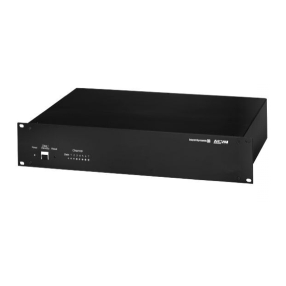
MCW-D 100 Control Unit
1.1 Controls and Indicators
Front view
(1)
(2)
(3)
(1)
Power LED. LED is illuminated green when the unit is switched on.
(2)
Standby button. When this button is pressed for more than 3 seconds all switched-on microphone units are switched off.
(3)
Reset. This button resets the system into the switch-on state (to press the reset button use a paper clip).
(4)
LEDs to indicate the status of the receiving channels. LED is illuminated green: the channel is vacant. LED is illuminated red:
the channel is occupied. Standard configuration: Channel 1 is used for data communication. Channel 2 to 7 for delegates,
channel 8 for the chairman.
Rear view
(5)
(18)
(18)
(5)
Connection for receiving antenna A/B (N-connector)
(6)
Fuse
(7)
Mains supply
(8)
On/Off-switch
(9)
RS 232 port for the connection of PC or media control system
(10)
Master Out, 3-pin XLR male, balanced, for the connection of external devices such as mixing consoles or sound contracting
system
(11)
Aux 1 Input, 3-pin XLR female, balanced, for the connection of external sound sources or as Insert Return
(12)
Connection for transmitting antenna (N-connector)
(13)
Level control for Master Out, RCA
(14)
Master Out, RCA, unbalanced, for the connection of external devices such as mixing consoles, sound contracting systems or
recorder (L + R)
(15)
Aux 2 Input, RCA, unbalanced, for the connection of external devices such as CD-player (L + R)
(16)
Level control for Aux 2 Input, RCA
As an option there are PCBs available for the connection of e.g. automatic mixers.
(17)
(Analogue, individual input/output (2 x 25-pin Sub-D) for e.g. interpreting applications and for individual transmitting/receiving
signals)
(18)
(Digital Input/Output, AES/EBU (XLR) and S/PDIF (RCA)).
16
(4)
(17)
(16)
(15)
(14)
(13)
(12)
(11)
(10)
(9)
(8)
(7)
(6)
(5)
Advertisement
Table of Contents

Related Manuals for Beyerdynamic MCW DIGITAL


Summary of Contents for Beyerdynamic MCW DIGITAL
- Page 1 OPERATING INSTRUCTIONS MCW DIGITAL Thank you for selecting the MCW Digital wireless conference system. Please take some time to read carefully through this manual before setting up the equipment. MCW-D 100 Control Unit 1.1 Controls and Indicators Front view Power LED. LED is illuminated green when the unit is switched on.
- Page 2 TE: To comply with FCC RF exposure compliance requirements, the following antenna installa- tion and device-operating configuration must be satisfied. Only authorized and certified beyerdynamic systems integrators may perform the installation of the antennas. There are no user serviceable parts or processes.
-
Page 3: Controls And Indicators
Mini stereo jack (3.5 mm) for the connection of recorders or headphones ATTENTION: This connection has been covered, because at present special headphones can be connected only. If you need this connection please contact beyerdynamic. Top View MCW-D 1021/1011 Delegate Microphone Unit Gooseneck microphone with illuminated ring... -
Page 4: Auto-Off Function
2.2 Setting up The microphone units have no separate on/off switch. They are switched on and off with the microphone button. By pressing the button briefly, the microphone unit is switched on. The LED (7) flashes for a moment and the LED (2) on the rear is illuminated. By pressing the button for more than 2 seconds the microphone unit is switched off and the LED (7) will illuminate twice red/green briefly. -
Page 5: Maintenance Of The Mcw-D Microphone Units
A headphone (e.g. DT 301) can be connected to the documentation output (4). We recommend a min. impedance of 200 Ω. ATTENTION: This connection has been covered, because at present special headphones can be connected only. If you need this connection please contact beyerdynamic. 2.6 CA 2455 External Power Supply The MCW-D microphone units can be powered with the CA 2455 external power supply unit which can be connected to the multi-function socket (1). - Page 6 Drawing 1 Drawing 2 at the top RX at the bottom TX...
-
Page 7: Charging Process
Note If an error has occured, try to start the charging process once again. If the LEDs are still flashing rapidly, please contact your beyerdynamic dealer. 4.2 Forming Mode The LE-D 10 charging units are equipped with a forming mode for the rechargeable batteries inside the microphone units. The batteries are formed and charged at the factory. -
Page 8: Technical Specifications
Components MCW-D 1021 Delegate microphone unit with loudspeaker ........Order # 459.119 MCW-D 1023 Chairman microphone unit with loudspeaker . - Page 9 If you need this connection please contact beyerdynamic. Connection ....... . . Tip = AF+...
- Page 10 Power supply ....... 110 - 240 V AC 50/60 Hz Fuse .
- Page 11 (2) This device must accept any interference received, including interference that may cause undesired operation. In accordance with FCC requirements, changes or modifications not expressly approved by beyerdynamic GmbH could void the user’s authority to operate this product. Any changes or modifications not expressly approved by the party responsible for compliance could...
-
Page 12: Ec Declaration Of Conformity
Model Numbers: MCW D 1011, MCW D 1013, MCW D 1021, MCW D 1023 MCW D 100 I, the undersigned, as an employee of beyerdynamic, hereby declare that the equipment specified conforms to the above Directive and Standards. Date: November, 2001...
Need help?
Do you have a question about the MCW DIGITAL and is the answer not in the manual?
Questions and answers