Beyerdynamic MCS 50 Operating Instructions Manual
Discussion system with sub-d-connection
Hide thumbs
Also See for MCS 50:
- Manual (8 pages) ,
- Specifications (7 pages) ,
- Interface protocol (3 pages)

Related Manuals for Beyerdynamic MCS 50


Summary of Contents for Beyerdynamic MCS 50
-
Page 1: Operating Instructions
BEDIENUNGSANLEITUNG OPERATING INSTRUCTIONS NOTICE D’UTILISATION MCS 50 Diskussionssystem mit Sub-D-Anschluß Discussion System with Sub-D-connection Système de conférence avec connexion Sub-D... - Page 2 Schwanenhals - Achtung Zur Vermeidung von Überdehnungen und frühzeitigem Verschleiß darf der Schwanenhals nur bis max. 90 Grad gebogen werden. Gooseneck - Caution In order to avoid overstretching and premature wear and tear never bend the gooseneck more than 90°. Col de Cygne - Attention Flexion de 90 degrés max.
-
Page 3: Table Of Contents
Technische Daten ..... Seite 20 Explosionszeichnung / Ersatzteilliste MCS 50......Seite 28 Explosionszeichnung / Ersatzteilliste Sprechstellen MCS 511, 513, 521, 523 . -
Page 4: Kurzbeschreibung
• Einstell-Regler auf der Unterseite für individuelle Ausgangslautstärke der Lautsprecher in der Sprechstelle, regelbar von der einge- stellten Lautstärke der Steuerzentrale MCS 50 von 0 dB bis -20 dB (z.B. bei Round-Table-Meetings können die Lautsprecher näher aneinander stehen, so daß wegen Rückkopplungsgefahr ein Sprechstellen-Lautsprecher leiser gestellt werden kann). - Page 5 1.2.1 Präsidentensprechstelle MCS 513, MCS 523 Die Präsidentensprechstelle ist mit 3 Tasten ausgestattet. Prior-Taste Die Funktion der Prior-Taste hängt davon ab, wie sie in der Diskussions-Steuereinheit MCS 50 konfiguriert wurde. Der Präsident kann entweder alle aktivierten Delegierten-Sprechstellen vorübergehend „muten“ oder ganz löschen. Mikrofon-Taste Die Mikrofon-Taste hat eine Zuschaltfunktion, sodaß...
- Page 6 33 - 64 Linie 1 Linie 2 (nur MCS 50/64) Hinweis: Werkseitig ist die Sprechstelle 1 als Präsident definiert. Änderungen können über den MCS-Editor vorgenommen werden. Achten Sie bei der Adressierung darauf, daß keine Doppeladressierung innerhalb der gleichen Linie vorkommt. Hilfreich ist der MCS- Editor (siehe Kapitel 6.8 „Statusabfrage“).
- Page 7 Pflege der MCS Sprechstellen Zum Reinigen der MCS Sprechstellen bei leichten Verschmutzungen wie Fingerabdrücke, Staub, Marmelade oder Fruchtsaft nehmen Sie ein feuchtes Tuch, Schwamm oder Bürste und einen flüssigen Haushaltsreiniger. Vor der Reinigung muß die Fläche gründlich angefeuchtet werden. Zum Schluß mit klarem Wasser nachwaschen. Achten Sie darauf, daß kein Wasser in die Mikrofonkapsel oder in das Gehäuse läuft.
-
Page 8: Mcs 50 Diskussions-Steuereinheit
(10) Anschluß für Aufnahmegerät, unsymm. (250 mV) (11) Sprechstellenanschluß Line 1, 15-pol. Sub-D-Buchse (12) Sprechstellenanschluß Line 2, 15-pol. Sub-D-Buchse (nur bei Version MCS 50/64) (13) RS 232: dient zum Anschluß von Bedien-PC via Mouse oder Touchscreen oder für weitere am Markt befindliche Konferenzsteuerungssysteme wie z.B. -
Page 9: Installation Mcs 50 Und Sprechstellen
Wenn die Sicherung F101 des integrierten Schaltnetzteils (siehe Nr. 200 in „Explosionszeichnung und Ersatzteilliste Diskussionssteuer- zentrale MCS 50“, Seite 24 bis 25) defekt ist, sollte das gesamte Schaltnetzteil ersetzt werden. Eine andere Sicherung mit einem höheren Wert als 6,3A kann das Schaltnetzteil zerstören. -
Page 10: Inbetriebnahme
Konfiguration In das Konfigurationsmenü gelangen Sie, wenn Sie bei der eingeschalteten MCS 50 beide Tasten gleichzeitig drücken. Die Pfeile im Display zeigen an, welche Taste am Gerät zu drücken ist, links (Reset) = M, rechts (N.o.m.) = L. Zum Verlassen der einzelnen Menüpunkte drücken Sie beide Tasten gleichzeitig. - Page 11 2. Parameter In diesem Menüpunkt wird die Betriebsart eingestellt. Betriebsart Möglich sind: Manuell, Wechsel, Anmeldung Weiter Reset N.o.m. In der ersten Zeile erscheint die aktuelle Einstellung. Mit der linken Taste (4) wird die Betriebsart Manuell Wechsel ausgewählt, mit der rechten Taste (5) wird die ausgewählte Betriebsart bestätigt und erscheint in Reset N.o.m.
- Page 12 5. Parameter In diesem Menüpunkt wird die Blinkzeit eingestellt; d.h. es wird die Zeit eingestellt, die den Blinkzeit Leuchtring in der Sprechstelle blinken läßt, bevor die Sprechstelle, nach Ablauf der Redezeit abge- Weiter Reset N.o.m. schaltet wird. Die Blinkzeit (hier im Beispiel wurden 6 Sekunden eingestellt) ist nur dann wirksam, wenn zuvor 6 Sek die Redezeit eingestellt wurde.
- Page 13 Der Pegelwert kann mit der linken Taste (4) absteigend, mit der rechten Taste (5) aufsteigend ein- gestellt werden. Reset N.o.m. Wichtig: Sprechlinie 2 Die Sprechlinie 2 ist nur bei der Version MCS 50/64 angeschlossen. Weiter Reset N.o.m. Reset N.o.m. Beim Drücken beider Taster wird der eingestellte Wert gespeichert und Sie gelangen zurück in das Hauptmenü. Für weitere Pegeleinstellungen müssen Sie wieder wie unter 8.
- Page 14 0 dB Die Höhen bzw. Tiefen können zwischen +12 dB und -12 dB eingestellt werden. Reset N.o.m. 11. Parameter Wichtig: Insert Die Menüpunkte „Insert“ und „Telefon“ haben bei der MCS 50 keine Funktion! Weiter Reset N.o.m. Reset N.o.m. Speichern Sobald alle Parameter eingegeben wurden, müssen zum Speichern beide Tasten (4) und (5) gleich- Systemcheck bitte warten zeitig gedrückt werden.
-
Page 15: Mcs-Systemkonfiguration Über Mcs-Editor
Klicken Sie auf OK und folgen Sie den Anweisungen auf dem Bildschirm. 6.3 Anschluß • Verbinden Sie den Serviceport der MCS 50 über ein Standard-RS 232-Anschlußkabel mit der seriellen Schnittstelle RS 232 an Ihrem • Werkseitig ist die serielle Schnittstelle „COM 2“ konfiguriert. Änderung siehe Kapitel „6.7 Übertragen der Daten“. - Page 16 6.4 MCS 50 - Erstellung einer neuen Konfiguration • Starten Sie Ihre installierte MCS-Editor-Software über das Start-Menü „Programme“. • Rufen Sie das Menü „Datei“ auf und klicken Sie auf den Befehl „Neu“. • Geben Sie die gewünschte Konfiguration in die MCS-Editor Maske ein.
- Page 17 6.7 Übertragen der Daten Zum Übertragen der Daten auf die Diskussions-Steuereinheit MCS 50 rufen Sie das Menü „Steuerung“ und den Befehl „Übertragen“ auf. Die Daten werden auf die Diskussions-Steuereinheit MCS 50 übertragen. Danach startet die MCS 50 einen erneuten Systemcheck und wenn das System „OK“...
-
Page 18: Glossar
6.9 Konfigurationsbeispiel „Anzahl Mikrofone“ (Nur MCS 50/64) In einer Linie können bis zu 32 Sprechstellen an die Steuerzentrale angeschlossen werden. Sollen jedoch z.B. in der 1. Linie 16 Sprechstellen und in der 2. Linie 17 Sprechstellen angeschlossen werden, müssen Sie wie nachfol- gend beschrieben vorgehen: 1. -
Page 19: Fehlercheckliste
Konfiguration den Eingang ein Pegel des jeweiligen Eingangsverstärkers Mit Hilfe der Funktionstasten an der ist zu gering eingestellt MCS 50 den Pegel des jeweiligen Ein- gangsverstärkers erhöhen (8. Parameter) Ton zerrt Eingangsschaltung übersteuert Mit Hilfe der Funktionstasten an der MCS 50 den Ton des jeweiligen Eingangs runterregeln (10. -
Page 20: Ausführungen
Konferenzbus (Line 1) ......15-pol. Sub-D-Buchse, max. 32 Sprechstellen Konferenzbus (Line 2) ......15-pol. Sub-D-Buchse, max. 32 Sprechstellen (nur bei MCS 50/64!) Anzeige . - Page 21 Luftfeuchtigkeit ......max. 90% Schutzmaßnahmen ......überlast-, dauerkurzschluß- und leerlauffest Audio Frequenzgang .
- Page 22 Abmessungen (ohne Mikrofon) ....Länge: 190 mm Breite: 155 mm Höhe: 52 mm Gewicht (mit Mikrofon und Anschlußkabel) ..1390 g Umgebungstemperatur .
- Page 23 Delegiertensprechstelle MCS 501 Stromversorgung ......+24 V über Konferenzbus-Leitung Stromaufnahme ......max. 84 mA NF-Übertragungsbereich .
- Page 24 Preis und weitere Informationen auf Anfrage 1 x 15-pol. Sub-D-Buchse, Konferenzbus 1 x Klinken-Schnellsteckbuchse für Schwanenhalsmikrofon mit Leuchtring 6-fach Klemmleiste (abnehmbar) für ... . . Prior-Taste Mikrofontaste Clear-Taste LED-Anzeige „Mikrofon ein“ (grün), 24 V / 20 mA ohne Vorwiderstand LED-Anzeige „Anmeldung“...
- Page 25 Anschluß MCS 553 L ACHTUNG: Verwenden Sie zum Anschluß der Sprechstellen an die MCS-Zentrale und der Sprechstelle untereinander nur von beyerdynamic empfohlene Anschlußkabel (siehe unter „Zubehör - optional“). Bei Verwendung selbstkonfektionierter Kabel muss auf korrekte Belegung geachtet werden, da sonst Sprechstellen und Zentrale zerstört werden können.
- Page 26 Systemanschlußeinheit MCS 563 Stromversorgung ......+24 V über Konferenzbus-Leitung Stromaufnahme ......max. 74 mA NF-Übertragungsbereich .
- Page 27 Anschluß MCS 563 L ACHTUNG: Verwenden Sie zum Anschluß der Sprechstellen an die MCS-Zentrale und der Sprechstelle untereinander nur von beyerdynamic empfohlene Anschlußkabel (siehe unter „Zubehör - optional“). Bei Verwendung selbstkonfektionierter Kabel muss auf korrekte Belegung geachtet werden, da sonst Sprechstellen und Zentrale zerstört werden können.
-
Page 28: Mcs
Explosionszeichnungen und Ersatzteillisten Diskussionssteuerzentrale MCS 50... - Page 29 Abb.Nr. Teil.Nr. Zeichnung Nr. Bezeichnung 553.093 BN 17-640/A Gehäuse, Oberteil 553.387 BN 17-644/A Gehäuse, Unterteil 322.881 Best.-Nr. 544.873 schwarz Klebefuss 391.018 DIN 965-M 3 x 8 Senkschraube 553.433 BN 56-990/A Frontplatte 503.576 DIN 965-M 5 x 12 Senkschraube 553.182 41 L 07563 600GNGE300 Litze 252.581 Nr.
-
Page 30: Sprechstellen Mcs 511, 513, 521, 523
Sprechstellen MCS 511, 513, 521, 523... - Page 31 Abb.Nr. Teil.Nr. Zeichnung Nr. Bezeichnung 533.807 BN 55-65/A Boden 533.815 BN 54-211/A Abschirmdeckel 524.719 LPR 8602-Mini 6,4 mm Abstandshalter 553.409 BN 56-989/A Rückplatte 187.135 DIN 6797-A 3,2 Zahnscheibe 554.049 3 x 8 Torx Linsenschraube 553530 B 7-676.00-00 Anschlußkabel 553.425 BN 17-642/B Gehäuse (MCS 513 + MCS 523) 553.417 BN 17-642/A...
-
Page 32: Short Description
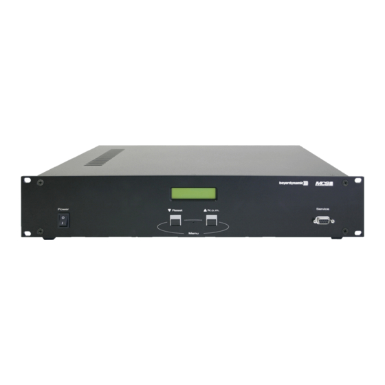
1.1 MCS 50 The MCS 50 is a self-contained discussion control unit with integrated power supply and processor control for 32 or 64 micro- phone units. It is a stand alone unit with multi-function buttons and LC-Display in a desktop housing that is suitable for 19" rack mounting. - Page 33 The chairman microphone unit is equipped with 3 buttons. Priority button The function of the priority button depends on how it has been configured in the MCS 50 discussion control unit. The chairman can either mute or clear all activated delegate microphone units.
- Page 34 33 - 64 Line 1 Line 2 (only MCS 50/64) Note: At the factory the microphone unit 1 has been configured as a chairman microphone unit. Using the MCS-Editor another microphone unit can be chosen as a chairman microphone unit.
- Page 35 Maintenance of the MCS Microphone Units For cleaning the MCS microphone units when they are slightly dirty (finger prints, dust, jam or juice) use a soft, damp cloth, sponge or brush and a liquid cleaning agent. Before cleaning the surface it must be moistened thoroughly. Afterwards it must be cleaned with clear water.
-
Page 36: Mcs 50 Discussion Control Unit
(10) Record: Connection to record documentations (250 mV) (11) Microphones Line 1, 15-pin Sub-D socket (12) Microphones Line 2, 15-pin Sub-D socket (MCS 50/64 version only!) (13) RS 232 for the connection of an operator’s PC (operation via mouse or touchscreen) or other available conference systems such as AMX ®... -
Page 37: Installation Of Mcs 50 And Microphone Units
Caution: If the F101 fuse of the integrated power supply (refer also to No. 200 in “Exploded View and Spare Parts, MCS 50 Discussion Control Unit”, page 48 to 49) is defective, you should replace the whole part. A different fuse with a higher value than 6.3 A can destroy the power supply. -
Page 38: Setting Up
5.2 Configuration You access the configuration menu when you press both buttons simultaneously of the switched on MCS 50. The arrows in the display indicate which buttons of the device have to be pressed, left (Reset) = M, right (N.o.m.) = L. To exit the individual menu items press both buttons simultaneously. - Page 39 2. Parameter In this menu the operation mode is adjusted. Operation mode Possibilities are: Autonomy, Override, Request-to-Talk More Reset N.o.m. The current adjustment is shown in the top line. The operation mode is chosen with the left Autonomy button (4), using the right button (5) the chosen operation mode is confirmed and appears in the top Override line as present operation mode.
- Page 40 5. Parameter In this menu the warning time is adjusted i.e. the time between which the illuminated ring starts Warning time flashing and the time when the microphone is switched off. More Reset N.o.m. The warning time (in this example 6 seconds) only operates when the talk time allowed has been 6 sec.
- Page 41 -6 dB Use the left (4) or right button (5) to adjust the level. Reset N.o.m. Important: Mic line The microphone line 2 is only connected when using the MCS 50/64 version. More Reset N.o.m. Reset N.o.m. When the two buttons are pressed simultaneously the adjusted value is saved and you will return to the main menu. If you want to carry out more level adjustments follow the steps as described in the 8.
- Page 42 10. Parameter In this menu treble and bass of the microphone units is adjusted. Tone control More Reset N.o.m. Pressing the right button (5) you can choose between the adjustment of treble and bass. Pressing Treble the left button (4) you enter the chosen menu item. More Reset N.o.m.
-
Page 43: Mcs System Configuration Via Mcs-Editor
6.3 Connection • Connect the service port of the MCS 50 via a standard RS 232 connecting cable to the serial RS 232 interface of your PC. • At the factory the serial interface has been set to “COM 2”. For changes refer to chapter “6.7 Downloading the data”. - Page 44 6.4 MCS 50 - Creation of a new configuration • Start the installed MCS-Editor Software via the “Programs” start menu. • Choose the “File” menu and click the “New” command. • Enter the desired configuration into the MCS-Editor mask. Number of Stations Enter the number of microphone units being used.
- Page 45 For downloading the entered data to the MCS 50 discussion control unit access the “Control” menu and the “Download” command. The data are downloaded to the MCS 50 discussion control unit. After this the MCS 50 is starting a new system check and if the system is “OK”, the default screen will appear.
-
Page 46: Glossary
6.9 Example for Configuration “Number of Stations” (MCS 50/64 only!) In each line up to 32 stations can be connected to the control unit. If for example 16 stations are to be connected in line 1 and 17 stations in line 2, you must do the following: 1. -
Page 47: Trouble Shooting
Use the MCS-Editor to switch on the are switched on input in the configuration Gain is too low on the selected input Use the buttons of the MCS 50 to increase the level of the concerning input amplifier (8. Parameter) Distorted sound... -
Page 48: Versions
Microphone Line 1 ......15-pin Sub-D-socket, max. 32 microphone units Microphone Line 2 ......15-pin Sub-D-socket, max. 32 microphone units (MCS 50/64 only!) Display . - Page 49 Audio Frequency response ......80 Hz to 19,000 Hz T.H.D........≤ 1% Power supply .
-
Page 50: Operating Instructions Mcs
Weight (without microphone) ....1390 g Ambient temperature ......0° - 50°C Colour . - Page 51 MCS 501 Delegate Microphone Unit Power supply ....... +24 V via microphone line Power consumption .
- Page 52 prices and more information on request 1 x 15-pin Sub-D socket, microphone line 1 x jack socket for gooseneck microphone with LED ring Removable terminal board with 6 connections for . . Priority button Microphone button Clear button LED indication “Microphone on” (green) 24 V / 20 mA without drop resistance LED indication “Request-to-Speak”...
- Page 53 For the connection of microphone units to the MCS Control Unit and for connection from microphone unit to microphone unit use only connecting cables recommended by beyerdynamic (refer also to the chapter “Optional Accessories”). If you use other cables make sure that you use cables with the correct wiring (refer also to the chapter “Technical Specifications”, otherwise the microphone units and the control unit may be damaged.
- Page 54 MCS 563 System Unit Power supply ....... +24 V via microphone line Power consumption .
- Page 55 For the connection of microphone units to the MCS Control Unit and for connection from microphone unit to microphone unit use only connecting cables recommended by beyerdynamic (refer also to the chapter “Optional Accessories”). If you use other cables make sure that you use cables with the correct wiring (refer also to the chapter “Technical Specifications”, otherwise the microphone units and the control unit may be damaged.
-
Page 56: Exploded View / Spare Parts Mcs
Exploded View and Spare Parts MCS 50 Discussion Control Unit... - Page 57 Illu. No. Part No. Drawing No. Description 553.093 BN 17-640/A Casing, top 553.387 BN 17-644/A Casing, bottom 322.881 Best.-Nr. 544.873 schwarz Adhesive base 391.018 DIN 965-M 3 x 8 Countersunk screw 553.433 BN 56-990/A Front panel 503.576 DIN 965-M 5 x 12 Countersunk screw 553.182 41 L 07563 600GNGE300...
-
Page 58: Mcs 511, 513, 521, 523 Microphone Units
MCS 511, 513, 521, 523 Microphone Units... - Page 59 Illu. No. Part No. Drawing No. Description 533.807 BN 55-65/A Bottom 533.815 BN 54-211/A Shielding 524.719 LPR 8602-Mini 6,4 mm Spacing piece 553.409 BN 56-989/A Rear plate 187.135 DIN 6797-A 3,2 Studded disc 554.049 3 x 8 Torx Oval head screw 553530 B 7-676.00-00 Connecting cable...
-
Page 60: Description Abrégée
Sous le dessous du poste, il y a un réglage individuel du volume du haut-parleur avec une plage de 0 à –20 dB en plus du régla- ge de niveau qui est contrôlé par le MCS 50 (Certaines installations nécessitent que le haut-parleur de certaines stations soit à un... - Page 61 Le poste président est équipé de 3 boutons. Bouton «Priority» La fonction du bouton «Priority» dépend de la configuration choisie dans la centrale MCS 50. Le président peut soit désactiver tem- porairement, soit désactiver définitivement tous les micros des postes délégués.
- Page 62 DIL 4 DIL 5 Ligne 1 Ligne 2 (seulement MCS 50/64) Note : Au départ de l’usine, le poste n° 1 est défini comme poste président, En utilisant le logiciel MCS Editeur d’autres postes peuvent être défini comme poste président.
- Page 63 Maintenance des postes MCS Pour le nettoyage des postes MCS quand ils sont très peu sales (trace de doigt, poussière, nourriture), utiliser un chiffon doux humide, une éponge ou une brosse et un produit de nettoyage liquide. Avant de nettoyer la surface, elle doit être dépoussiéré pro- fondément.
-
Page 64: Centrale De Contrôle Mcs
(11) Microphone: Line 1 Sub-D 15 broches femelle. (12) Microphone: Line 2 Sub-D 15 broches femelle (seulement version MCS 50/64). (13) RS 232: Pour le raccordement d’un PC de commande (avec une souris ou un écran tactile) ou d’autres systèmes de contrôle tels que: AMX©... -
Page 65: Installation De La Centrale Mcs 50 Et Des Postes
Attention : Si le fusible F 101 du bloc d’alimentation intégré ( Etiquette N° 200 sur «Exploded View and Spare Parts, MCS 50 Discussion Control Unit», pages 72 et 73) est défectueux, vous devez remplacer le bloc d’alimentation entier. Un fusible différent avec une valeur plus grande que 6,3 A peut détruire le bloc d’alimentation. -
Page 66: Opération
5.2 Configuration Lorsque le MCS 50 est en service, appuyez simultanément sur les deux boutons pour sélectionner le Menu de configuration. Les flèches dans l’afficheur vous montrent les boutons sur lesquels vous devez appuyer : Gauche (Reset)=4, Droite (N.o.m)=5. Pour quitter un Menu individuel, appuyer sur les deux boutons en même temps. - Page 67 2. Paramètre Dans ce Menu, on peut choisir le mode de fonctionnement. Les possibilités sont : Manuel, Altern, Mode de travail Suivant Appel (Demande de parole). Reset N.o.m. Le choix actuel est indiqué sur la ligne du haut de l’afficheur. Le mode de fonctionnement est choi- Manuel Altern.
- Page 68 5. Paramètre Clignotement Ce Menu vous permet de régler la durée du clignotement, c’est-à-dire le temps pendant lequel l’an- Suivant neau de signalisation d’un poste clignote avant que le microphone ne soit désactivé. Reset N.o.m. La durée du clignotement (6 secondes dans cet exemple) n’est activée que si la durée de parole a 6 Sec.
- Page 69 Appuyer sur le bouton de droite (5) pour ajuster le niveau. -6 dB Reset N.o.m. Important: Ligne 2 Suivant La Ligne 2 microphone existe seulement avec la version MCS 50/64. Reset N.o.m. Arret Marche Reset N.o.m. Quand les deux boutons sont appuyés simultanément, les valeurs ajustées sont mémorisées et le Menu Principal est affiché de nou- veau.
- Page 70 10. Paramètre Ce Menu permet d’ajuster le correcteur des fréquences graves et aiguës de la Ligne microphone des Egalisation postes. Suivant Reset N.o.m. En appuyant sur le bouton de droite (5) vous pouvez choisir entre le réglage de graves ou celui des Aigues Suivant aiguës.
-
Page 71: Configuration Du Système Mcs À L'aide De L'editeur Mcs
5.3 Ajustement des paramètres spécifiques utilisateur Important: Comme la MCS 50 est livrée avec un paramétrage Usine, tous les paramètres doivent être ajustés suivant le choix de l’utilisateur lors de la première mise en service. Pour ajuster les paramètres Utilisateur, vous devez appuyer sur les boutons droite (5) et gauche (4) Chargement des simultanément tout en mettant la MCS 50 sous tension. - Page 72 6.4. MCS 50– Création d’une nouvelle configuration • Démarrez le logiciel MCS Editeur par le Menu Démarrer. • Sélectionner le menu «Fichier» et cliquez sur l’option «Nouveau». • Entrer la configuration de votre choix dans le MCS Editeur. Nb. Microphones: Entrez le nombre de postes utilisés.
- Page 73 6.7 Transfert des données Pour transférer les données vers la centrale MCS 50, sélectionnez le menu «Edition» et la commande «Charger». Les données sont alors transférées vers la MCS 50. Après cela la MCS 50 démarre un nouveau test du système et si tout est correct, l’affichage standard apparaît.
-
Page 74: Glossaire
6.9 Exemple de configuration «Nombre de microphones» Jusqu’à 32 postes d’appel peuvent être connectés sur une ligne au poste de commande. Au cas où pourtant, par exemple, 16 postes d’appel étaient connectés sur une première ligne et 17 sur une deuxième, veuillez procé- der comme indiqué... -
Page 75: Dépannage
(10. Paramètre) Câble défectueux Utilisez un autre câble. Aucune liaison entre le PC et la MCS 50. Port mal configuré dans le MCS Editeur. Dans le MCS Editeur, changez la configu- ration du port. Par exemple, il n’y a pas plus de 5 postes Une déconnexion sous tension d’un câble... -
Page 76: Modèles
Tension de sortie ......+ 24 V, + 5 V, + 15 V, - 15 V. Consommation ......38 W (MCS 50/32) 60 W (MCS 50/64) Courant de sortie à... - Page 77 Audio Réponse en fréquence ......80 Hz à 19 kHz. Distorsion ........≤ 1 %. Alimentation .
- Page 78 Poids (Sans microphone) ..... . 1390 g Température de fonctionnement ....0° à 50°C. Couleur .
- Page 79 MCS 501 Poste Délégué Alimentation ....... + 24 V via le bus de raccordement. Consommation .
- Page 80 Affichage LED "Microphone MARCHE" (vert), 24 V / 20 mA sans résistance série Affichage LED "Demande de parole" (rouge). 24 V / 20 mA sans résistance série Dimensions (sans microphone) Longueur: 203 mm. Largeur: 97 mm. Hauteur: 47 mm. Poids (avec microphone et câble de connexion ) ..860 g. Température de fonctionnement .
- Page 81 Pour le raccordement des postes d’orateur à la centrale MCS et des postes d’orateur entre eux, utilisez uniquement les câbles de raccordement recommandés par beyerdynamic (cf. au chapitre "Accessoires - option"). En cas d’utilisation de câbles fabriqués par vous-même, il convient d’observer l’affectation et la connexion correctes sinon les postes d’orateur et la centrale risquent d’être détériorés.
- Page 82 MCS 563 Unité de raccordement du système Alimentation ....... + 24 V via le bus de raccordement. Consommation .
- Page 83 Pour le raccordement des postes d’orateur à la centrale MCS et des postes d’orateur entre eux, utilisez uniquement les câbles de raccordement recommandés par beyerdynamic (cf. au chapitre "Accessoires - option"). En cas d’utilisation de câbles fabriqués par vous-même, il convient d’observer l’affectation et la connexion correctes sinon les postes d’orateur et la centrale risquent d’être détériorés.
-
Page 84: Exploded View / Spare Parts Mcs
Exploded View and Spare Parts MCS 50 Discussion Control Unit... - Page 85 Illu. No. Part No. Drawing No. Description 553.093 BN 17-640/A Casing, top 553.387 BN 17-644/A Casing, bottom 322.881 Best.-Nr. 544.873 schwarz Adhesive base 391.018 DIN 965-M 3 x 8 Countersunk screw 553.433 BN 56-990/A Front panel 503.576 DIN 965-M 5 x 12 Countersunk screw 553.182 41 L 07563 600GNGE300...
-
Page 86: Mcs 511, 513, 521, 523 Microphone Units
MCS 511, 513, 521, 523 Microphone Units... - Page 87 Illu. No. Part No. Drawing No. Description 533.807 BN 55-65/A Bottom 533.815 BN 54-211/A Shielding 524.719 LPR 8602-Mini 6,4 mm Spacing piece 553.409 BN 56-989/A Rear plate 187.135 DIN 6797-A 3,2 Studded disc 554.049 3 x 8 Torx Oval head screw 553530 B 7-676.00-00 Connecting cable...
-
Page 88: Konformitätserklärung
MCS 1011, MCS 1013, MCS 1021, MCS 1023 MCS 1036, MCS 1038, MCS 1020 MCS 1213, MCS 1223, MCS 1613, MCS 1623 I, the undersigned, as an employee of beyerdynamic, hereby declare that the equipment specified con- forms to the above Directive and Standards. Date: 1. - Page 90 NOTIZEN • NOTES...
- Page 92 Tel. +44 (0)1444 / 258 258 Fax +49 (0 )71 31 / 617-224 Fax +1 (631) 293-3288 Fax +44 (0)1444 / 258 444 E-mail: info@beyerdynamic.de E-mail: salesUSA@beyerdynamic-usa.com E-mail: sales@beyerdynamic.co.uk Internet: www.beyerdynamic.de Internet: www.beyerdynamic-usa.com Internet: www.beyerdynamic.co.uk DEF 6/BA MCS 50 (28.08.03)/556.203/ Printed in Germany...
Need help?
Do you have a question about the MCS 50 and is the answer not in the manual?
Questions and answers