
Related Manuals for LG GLOFA-GM Series


Summary of Contents for LG GLOFA-GM Series
- Page 1 User’s Manual LG Programmable Logic Controller Cnet I/F Module G3L-CUEA G4L-CUEA GLOFA-GM G6L-CUEB G6L-CUEC G7L-CUEB G7L-CUEC LG INDUSTRIAL SYSTEMS...
- Page 2 This user’s manual describes functions of Cnet I/F module. Please read this manual carefully to understand the functions thoroughly prior to system design. Revision record Revision record Date of issue revised Contents revised edition print GM7 Cnet I/F module added revision 2000.01.10 Functions of frame editor Version 2.0 added...
-
Page 3: Table Of Contents
Contents Chapter 1 Introduction 1-1~1-7 1.1 Module selection per CPU type 1.2 Functions of Version 2.0 1.2.1 Version check 1.2.2 Added functions introduction of Version 2.0 1.2.3 Established functions 1.2.4 Frame editor Version 2.0 1.2.5 Added function of Version 2.0 Chapter 2 Definition of terms 2-1~2-6 Chapter 3 Product specification... - Page 4 4.3 How to set transmission specifications 4-11 4.3.1 Setting items 4-11 4.3.2 How to set 4-12 4.3.3 Reading setting values 4-16 4.3.4 Transmission specification setting of Gm7 series 4-17 4.4 How to connect to modem 4-19 4.4.1 Connection to dedicated modem (RS-232C) 4-20 4.4.2 Connection to dial-up modem (RS-232C) 4-27...
- Page 5 6.2 System configuration unavailable 6-10 6.2.1 Dial-up modem communication between Cnet I/F modules 6-10 6.2.2 GMWIN connection using RS-422 channel of Cnet I/F module 6-11 Chapter 7 Communication program 7-1~7-132 7.1 User defined communication 7.1.1 Introduction 7.1.2 User defined operation 7.1.3 User defined Function Block (SND_MSG,RCV_MSG) 7.1.4 Example of user defined programming 7-12...
- Page 6 8.2 Communication system between Cnet I/F modules using optical modem 8.2.1 Exercising program 8.3 GMWIN connection using dial-up modem 8-21 8.3.1 Exercising program 8-21 8.4 Communication with GOLDSEC MJUC24 8-25 8.4.1 Exercising program 8-25 8.5 Communication with MASTER-K 1000H 8-30 8.5.1 Exercising program 8-30 8.6 Communication with HEX communication equipment...
- Page 7 11.2.2 Error code ERR-3 : communication command error 11-5 11.2.3 Error code ERR-4, ERR-5 : Receive monitor data error 11-7 11.2.4 Error code ERR-6, ERR-7 : Transmission monitor data error 11-8 11.2.5 Error code ERR-8, ERR-9 : Error on dedicated communication 11-9 11.2.6 Error code ERR-10 : error on GMWIN connection 11-11...
- Page 8 Chapter 1 Introduction Chapter 1 Introduction This user’s manual describes Cnet (Computer network) I/F module of GLOFA PLC network system. Cnet is GLOFA PLC network system using computer link module. Cnet has the connection function with different model to communicate with communication devices of various different type protocols such as other company’s PLC and computer, etc., and the function of modem communication to control remote PLC, and it has the following characteristics.
-
Page 9: Chapter 1 Introduction 1-1~1-7
Chapter 1 Introduction 1.1 Module selection per CPU type As 4 types of the modules are developed according to CPU types, appropriate module shall be selected for CPU type and its service. [Table1.1] describes selection guide of module per CPU type. Module selection per CPU type [Table1.1] Number of... -
Page 10: Functions Of Version
Chapter 1 Introduction 1.2 Functions of Version 2.0 This module has been operated in various application fields at home and abroad since released along with steady increasing performance via continuous Version-Up to answer the diverse requests of customers and to reinforce the reliability. - Page 11 Chapter 1 Introduction 1) CPU O/S Ver. check Cnet Ver.2.0 performs the most basic functions for initial running and flash memory operation and Ver.1.7 or less performs all functions of Cnet. CPU O/S can be upgraded only by CPU change of Cnet I/F module. Versions of Cnet I/F modules are classified on the basis of CPU O/S with the following procedure for version check.
- Page 12 Chapter 1 Introduction 2) FLASH O/S Ver. check For Cnet I/F module Ver. 2.0 or later, all functions to embody Cnet functions are saved in flash memory, and version check and upgrade are available through Frame Editor. Flash O/S version can be checked by Frame Editor if CPU O/S is of Ver.
-
Page 13: Added Functions Introduction Of Version
Chapter 1 Introduction 1.2.2 Added functions introduction of Version2.0 [Table1.2] shows configuration of main functions of Ver.2.0. [Table1.2] Configuration of main functions added to Ver.2.0. Comparison between contents Items Remark Ver.1.0 ~ 1.7 Ver.2.0 or later Mode change during operation Operating mode of module is is available with On-line mode set via H/W using switch. -
Page 14: Established Functions
Chapter 1 Introduction 1.2.3 Established functions Ver. 2.0 has been designed in 100% of compliance with the established versions and hardware configuration is the same as the former versions of products as upgraded via software Ver.-Up without hardware change. Accordingly, mounting and communicating connection with PLC CPU, user defined communication, dedicated communication, GMWIN connection, modem communication function, etc. -
Page 15: Chapter 2 Definition Of Terms 2-1~2-6
Chapter 2 Definition of terms Chapter 2 Definition of terms This chapter describes the communication terms used in this user’s manual. 1) Communication type A) Simplex This is the communication type that data is transferred in constant direction. Information can not be transferred in the reverse direction. - Page 16 Chapter 2 Definition of terms B) Parallel transmission This type is used in printer, etc., which transmits data in unit of 1 byte, so the speed is high and the accuracy of data is reliable. However, the longer the transmission distance is, the higher the cost of installation is geometrically.
- Page 17 Chapter 2 Definition of terms 4) Protocol This is communication rule established in relation between the transmission side and the receiving side of information in order to send and accept information between two computers/terminals or more without error, effectively, and reliably. In general, this specifies call establishment, connection, structure of message exchange form, re-transmission of error message, procedure of line inversion, and character synchronization between terminals, etc.
- Page 18 Chapter 2 Definition of terms the same signal line. Accordingly, RS-422 executes the full-duplex type of communication and RS-485 executes the half-duplex type of communication. 11) Half Duplex Communication Two-way communication is available, however simultaneous communication of transmission & receiving isn’t available.
- Page 19 Chapter 2 Definition of terms Since the transmission line is separated from the receiving line, simultaneous transmission & receiving is available without data impact, so called as Full Duplex Communication. The figure shows an example of structure based on RS-422 of Full Duplex Communication. Since transmission terminal of the master station and receiving terminals of the slave stations are connected to one line, and transmission terminals of the slave stations are linked with receiving terminal of the master station, the communication between slave stations is unavailable with the restricted function of multi-master.
- Page 20 Chapter 2 Definition of terms ACK, EOT, ETX ] for synchronization, parity for detecting error, and BCC. The structure of frame used for serial communication of Cnet is as follows. [Structure of general TX / RX frame] Required frame Segment Header Station Tail...
-
Page 21: Chapter 3 Product Specification 3-1~3-12
* Max. impact acceleration:147 ㎨(15G) Impact proof IEC 61131-2 * Authorized time :11 ㎳ * Pulse wave : Sign half-wave pulse (Each 3 times in X,Y,Z directions) Test spec. reference of LG Square wave impulse noise ±1,500V Industrial Systems Static electric discharging... -
Page 22: Performance Specifications
[Note2] GM3/4/6/7 function telephone line by connecting external modem to the module. Supporting multi-drop / 1:1 communication Dedicated mode with dedicated protocol of LG Industrial GM3/4/6/7 Systems PLC remote control is available through GMWIN mode GM3/4/6/7 GMWIN connection function... - Page 23 Chapter 3 Product specification Item Specification Remark Transmission RS-232C : Max. 15m(extendible by using modem) GM3/4/6/7 distance RS-422 : Max. 500m Loop-Back diagnosis / Indication of operation status with 16 LEDs during Diagnosis function GM3/4/6 operation (with 8 LEDs for GM6) G3L-CUEA 160mA or less G4L-CUEA...
-
Page 24: Cable Specifications
Item .: Low Capacitance LAN Interface Cable Type : LIREV-AMESB Size .: 2P X 22AWG(D/0.254 TA) Manufacturer : LG Cable Co., Ltd [Table 3.3] Specifications of twisted pair cable 1) Electric characteristics Test item Unit Characteristics Test conditions Conductor resistance Ω... -
Page 25: Terminating Resistance
Chapter 3 Product specification 3.4 Terminating resistance For communication via RS-422 channel, terminating resistance from external must be connected. Terminating resistance has the function to prevent distortion of signal by reflected wave of cable for long-distance communication, and the same resistance (1/2W) as characteristic impedance of cable must be connected to terminal of network. - Page 26 Chapter 3 Product specification How to connect terminating resistance during RS-485 connection GM3/4/6 unit PLC #1 PLC #2 PLC #(N-1) PLC #N GM7 unit · · · · · · · · PLC #1 PLC #2 PLC #(N-1) PLC #N...
-
Page 27: Structure
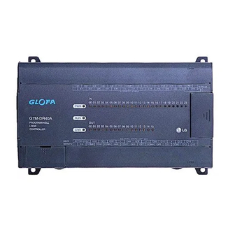
Chapter 3 Product specification 3.5 Structure 3.5.1 Part names of G3L-CUEA G3L-CUEA Name Contents RUN/BPS TX/BPS RX/BPS RS-232C ACK/DATA-BIT LED displaying Indication of operating status of G3L- NAK/PARITY ① ERR/EVEN-ODD ① MODEM/STOP-BIT SYS-RUN section CUEA (see Appendix A) RUN/BPS TX/BPS RX/BPS RS-422 ACK/DATA-BIT... -
Page 28: Part Names Of G4L-Cuea
Chapter 3 Product specification 3.5.2 Part names of G4L-CUEA G4L-CUEA Name Contents RUN/BPS RUN/BPS TX/BPS TX/BPS LED displaying Indication of operating status of G4L- ① RX/BPS RX/BPS ① ACK/DATA ACK/DATA section CUEA (see Appendix A) NAK/PARITY NAK/PARITY ERR/EVEN-ODD ERR/EVEN-ODD MODEM/STOP RS-485/STOP Switch for indication of parameter and SYS-RUN... -
Page 29: Part Names Of G6L-Cueb
Chapter 3 Product specification 3.5.3 Part names of G6L-CUEB COM-ERROR Name Contents MODEM ① SYS-RUN/ERR LED displaying Indication of operating status of G6L- G 6 L - C U E B ① section CUEB (see Appendix A) Setting of operation mode ②... -
Page 30: Part Names Of G6L-Cuec
Chapter 3 Product specification 3.5.4 Part names of G6L-CUEC Name Contents COM-ERROR RS-485 ① LED displaying Indication of operating status of G6L- SYS-RUN/ERR ① G 6 L - C U EC section CUEC (see Appendix A) Setting of operation mode ②... -
Page 31: Part Names Of G7L-Cueb
Chapter 3 Product specification 3.5.5 Part names of G7L-CUEB GLOFA G7L-CUEB PROGRAMMABLE LOGIC CONTROLLER TM/TC MODE D-SUB ON OFF Name Contents LED displaying section See LED display. ① Connectors for connection with external RS-232C connector ② devices Mode switch For selecting of TM/TC operation ③... -
Page 32: Part Names Of G7L-Cuec
Chapter 3 Product specification 3.5.6 Part names of G7L-CUEC GLOFA G7L-CUEC PROGRAMMABLE LOGIC CONTROLLER Name Contents Connectors for connection RS-422/485 interface ① with external devices LED displaying section See LED display. ② Connectors for connection with digital I/O For extended connector ③... -
Page 33: Chapter 4 Performance Specification 4-1~4-33
Chapter 4 Performance specification Chapter 4 Performance specification 4.1 Operation mode setting The operation mode of this module is set with operation mode switch on the front, and interlocking/stand-alone mode or operation mode for each channel is determined according to the operation mode. Setting method of operation mode is after selecting required mode adjusting switch values of operation mode with power off, set by power on. - Page 34 Chapter 4 Performance specification Remark [Note1] In interlocking mode, main channel is set to RS-232C, RS-422 channel is operated as data path of channel RS-232C (channel RS-422 disabled), and transmission spec. is operated according to setting value of RS-232C. [Note2] RS-232C/RS-422 channels are operated separately in stand-alone mode [Note3] Off-line mode sets the operation mode with mode switch.
-
Page 35: Channel Operation In Interlocking Mode
Chapter 4 Performance specification 4.1.1 Channel operation in interlocking mode In interlocking mode, channels RS-232C and RS-422 are operated as interlocked with each other. In other words, the data received via channel RS-232C is sent via channel RS-422, and the data received via channel RS-422 is sent via channel RS-232C in reverse. -
Page 36: Channel Operation In Stand-Alone Mode
Chapter 4 Performance specification 4.1.2 Channel operation in stand-alone mode In stand-alone mode, channels RS-232C and RS-422 are operated independently to allow simultaneous Tx / Rx in separate transmission specifications. Therefore, transmission specifications can be set per RS-232C and RS-422 channel, and the operation is started/stopped according to channels. -
Page 37: Channel Operation In Self Diagnosis Mode(Loop-Back)
Chapter 4 Performance specification 4.1.3 Channel operation in self diagnosis mode(Loop-Back) Loop-Back diagnosis is a function to check if communication channel is normally operated by itself without connection with external devices, and is operated only if the mode switch is in Loop-Back mode. For the details of operation method, see ‘Chapter 9 Diagnosis function’. -
Page 38: Method Of Serial Interface
Chapter 4 Performance specification 4.2 Method of serial interface 4.2.1 RS-232C interface Channel RS-232C uses 9-pin connector (Female) for communication with external devices. The names and functions of pins and data directions are as shown in the figure below. [Figure 4.3] Pin specifications of 9-pin connector for RS-232C Signal direction Pin No. - Page 39 Chapter 4 Performance specification 1) How to connect RS-232C connector during modem connection Cnet I/F module can communicate with devices of long distance as connected with modem. Modem and RS- 232C channel shall be connected as in [Figure4.4] below. [Figure 4.4] Cable connection between RS-232C and modem Cnet(9-PIN) Modem side(25-PIN) Connection No.
- Page 40 Chapter 4 Performance specification If CD signal is not controlled by external devices, it must be connected in 3-wire type connection as in [Figure 4.6]. Recent PC does not control CD signal line, so when connecting with PC, it must be connected in 3-wire type. [Figure 4.6] Connection of 3-wire type (without handshake) Computer/communication Cnet(9-PIN)
-
Page 41: Interface
Chapter 4 Performance specification 4.2.2 RS-422 interface Channel RS-422 uses 6-pin connector (Terminal Block) for communication with external devices. The names and functions of pins and data directions are as shown in [Figure 4.7] below. [Figure 4.7] Pin specifications of 6-pin connector for RS-422 Signal direction Pin No. - Page 42 Chapter 4 Performance specification [Figure 4.9] RS-485 connection Computer link side Signal direction External communication (Cnet<--->external devices) device Pin No. Name RDA(RXA) RDB(RXB) SDA(TXA) SDB(TXB) S.G(SG) [Figure4.9] shows how to connect RS-485 multi-drop communication. In case of multi-drop communication, to connect with external devices, RDA and SDA, RDB and SDB of RS-422 channel shall be connected each other.
-
Page 43: How To Set Transmission Specifications
Chapter 4 Performance specification 4.3 How to set transmission specifications 4.3.1 Setting items Transmission specifications of transmission speed and data type of data/stop bit are set by Frame Editor in this module. Accordingly, user is required to set the following items in accordance with the transmission specifications of the system to be used. -
Page 44: How To Set
Chapter 4 Performance specification 4.3.2 How to set Transmission specifications are set by Frame Editor with the setting sequence as below. 1) Run Frame Editor in Windows. 2) The following initial setting screen is displayed Selection area of communication channel Setting area of basic parameter... - Page 45 Chapter 4 Performance specification 5) Enter station No. for dedicated mode or other company’s dedicated mode. Station No. can be set from 0 to 31. 6) Set the other basic parameters(communication speed, data bit, parity, and stop bit) in accordance with the communication type.
- Page 46 Chapter 4 Performance specification A) If no response in time If the message above is displayed, RS-232C cable between PC and PLC may not be connected, or the connection status may be abnormal. Check the connection status of RS-232C cable to verify that RS-232C cable is correctly connected with loader port of PLC CPU.
- Page 47 Chapter 4 Performance specification In Write dialog box as above, set the position where the module to be written is mounted with slot No., and select writing with communication option set to ‘basic parameter’. Remark [Note1] If user defined frame has been prepared, let it set to frame in communication option to write frame only.
-
Page 48: Reading Setting Values
Chapter 4 Performance specification Select the slot No. of computer link module and the channel of operation to switch over in the dialog box for operation change and click on [Run] button to start the correspondent channel. In these methods, run the correspondent channel to start operation after basic parameters are set and written according to channels RS-232C/RS-422. -
Page 49: Transmission Specification Setting Of Gm7 Series
Chapter 4 Performance specification 4.3.4 Transmission specification setting of GM7 series Transmission specification of GM7 series is composed as set inside the communication parameter of GMWIN without Frame Editor. 1) Select and execute the communication parameter after GMWIN is started. 2) Select communication type of the communication parameter in accordance with the contents to set. - Page 50 Chapter 4 Performance specification 3) Select self-station number, communication speed, parity bit, data bit, stop bit and communication channel of Cnet I/F module to communicate among items in communication type. 4) If parameter setting of communication type is completed, enter protocol and transmission mode below and then select writing of communication parameter for program.
-
Page 51: How To Connect To Modem
Chapter 4 Performance specification 4.4 How to connect to modem Cnet I/F module has a function for long-distance communication via RS-232C channel using public line. How to connect to public line using Cnet I/F module is as follows 1) Dedicated modem communication via dedicated line 2) Dial-up modem communication via normal telephone line Since these two types of communication differ from each other according to characteristics of the line, they shall be used with modem connection as set differently by Frame Editor. -
Page 52: Connection To Dedicated Modem (Rs-232C)
Chapter 4 Performance specification 4.4.1 Connection to dedicated modem (RS-232C) Modem selection 4.4.1.1 Performance of dedicated modem communication with Cnet I/F module depends on the condition and status of dedicated modem and dedicated line. Since low-performance modem or inferior line causes deterioration of communication, the modem as specified below is recommended for reliable communication. - Page 53 Chapter 4 Performance specification edicated modem setting 4.4.1.3 D Most dedicated modems are designed to set operation mode via dip switch or LED display window according to modem manufacturers. Operation type needs setting as agreed with communication type with Cnet I/F module referring to user’s manual for modem.
- Page 54 Chapter 4 Performance specification Remark [Note1] This module can be connected with dedicated modem/dial-up modem only via RS-232C channel. [Note2] For such modems as optical modem and wireless modem supporting RS-422 communication, communication via RS-422 channel is available without additional setting in Cnet I/F module. [Table4.5] Switches available to connect with modem Module type Switch value...
- Page 55 Chapter 4 Performance specification Set communication type to dedicated modem in basic parameter setting in Figure above. (Basic value is set to null modem) Write basic parameters and change communication in [Online] connection of Frame Editor to switch RS- 232C channel over to communication run. If switched to communication run, operation setting of Cnet I/F module is completed and the setting contents are saved in flash memory of the module as reserved even if powered off.
- Page 56 Chapter 4 Performance specification 1) Module’s LED status before communication starts G4L-CUEA RUN/BPS : always ‘ON’ RUN/BPS RUN/BPS MODEM/STOP : always ‘ON’ TX/BPS TX/BPS SYS-RUN : dimly ‘ON’ RX/BPS RX/BPS ACK/DATA ACK/DATA NAK/PARITY NAK/PARITY ERR/EVEN-ODD ERR/EVEN-ODD MODEM/STOP RS-485/STOP SYS-RUN SYS-ERR RS-232C RS-422 2) Module’s LED status during normal communication...
- Page 57 Chapter 4 Performance specification [Table4.6] Checklist for module’s LED LED type If normal If abnormal Action to take 1) ..Run RS-232C channel operation using Frame Editor 1) Check cable connection between module and dedicated modem Flash if in No flash 2) Check setting of mode program and station number based on transmission module operation mode...
- Page 58 Chapter 4 Performance specification LED type If normal If abnormal Action to take 1) Check if data is transmitted from the other station’s dedicated modem Flash 2) Check status of dedicated line 3) Check connection status of dedicated line If TXD LED doesn’t flash either, follow the action for TXD LED to troubleshoot 1) Flash if in Check cable connection between module and dedicated...
-
Page 59: Connection To Dial-Up Modem (Rs-232C)
Chapter 4 Performance specification 4.4.2 Connection to dial-up modem (RS-232C) Cnet I/F module has a function for long-distance communication using public line. This function allows the long- distance communication by connecting external modem to module in PC or remote devices equipped with telephoning function via public line. - Page 60 Chapter 4 Performance specification How to connect the modem with this module 4.4.2.2 Dial-up modem and Cnet I/F module are connected with 9-pin cable via RS-232C channel as wired as below. Cnet (9-PIN) Mode side (25-PIN) Connection No. and Signal direction [Note1] Pin No.
- Page 61 Chapter 4 Performance specification Connect interface cable linked as specified in 4.4.2.2 for pin connection, to RS-232C port of this module and DTE connection terminal of the modem. A) Connect the phone line to line terminal of modem. B) Let modem and PLC powered on. C) Run Frame Editor to set communication type of RS-232C channel to modem and input initializing command.
- Page 62 Chapter 4 Performance specification Write basic parameters and change communication in [Online] connection of Frame Editor to switch RS-232C channel over to communication run. If switched to communication run, operation setting of Cnet I/F module is completed and the setting contents are saved in flash memory of the module as reserved even if powered off.
- Page 63 Chapter 4 Performance specification Remark [Note1] TX LED of module flashes in a cycle of 1 second until modem is completely initialized. If modem is initialized normally, TX LED and RX LED flash almost simultaneously indicating that normal response of modem to initializing request of modem is performed. In this case, TX/RX LEDs are no more flashing.
- Page 64 Chapter 4 Performance specification LED status during normal communication G4L-CUEA RUN/BPS RUN/BPS RUN/BPS : always ‘ON’ TX/BPS TX/BPS RX/BPS RX/BPS TX/BPS : if in transmission, ‘ON’ ACK/DATA ACK/DATA RX/BPS : if in receiving, ‘ON’ NAK/PARITY NAK/PARITY MODEM/STOP : always ‘ON’ ERR/EVEN-ODD ERR/EVEN-ODD SYS-RUN : dimly ‘ON’...
- Page 65 Chapter 4 Performance specification LED type If normal If abnormal Action to take 1) Check cable connection ERROR Flash 2) Check if modem is deficient 1) Download communication type of RS-232C channel as set to modem via Frame Editor MODEM 2) Check if channel operation mode is set to stand-alone mode 2) LED display &...
-
Page 66: Chapter 5 Frame Editor 5-1~5-43
100% compliance with former versions of Frame Editors along with additional functions to support supplemented features of Cnet Ver.2.0. Updated version of Frame Editor can be used through downloads in Internet Home Page of LG Industrial Systems(http://www.lgis.lg.co.kr/fa). This manual is based on Frame Editor Ver.2.0 for instruction of its functions. Basic functions of Frame Editor are as follows. -
Page 67: Screen Configuration And Menu
Chapter 5 Frame Editor 5.2 Screen configuration and menu [Figure 5.1] shows the initial screen when Frame Editor is run for setting of communication channel, basic parameters and frame. [Figure 5.1] Basic screen of Frame Editor Radio button to select channel Setting area of basic communication parameters and modem... - Page 68 Chapter 5 Frame Editor Type Menu Function Disconnect Disconnect to PLC Read parameters and frame in module Read Write parameters and frame in module. Communication channel to perform Write with depends on communication channel setting in the basic screen Online Write Run or Stop the operation of each channel Change...
- Page 69 Chapter 5 Frame Editor Type Menu Function Change operation mode of module in online. Ver. 2.0 Online change mode Online Write/Read other company’s dedicated driver saved in flash memory and check Cnet Flash memory O/S version of flash memory. Ver. 2.0 Select communication port to use among COM1 ~ COM4.
- Page 70 Chapter 5 Frame Editor Type Menu Function Receiving monitor screen Receive frame Monitor Display data transmitted via this module on the screen by reading through Frame Editor Send frame Transmission monitor can use RS-232C channel only.
-
Page 71: Basic Parameter Setting
Chapter 5 Frame Editor 5.2.1 Basic parameter setting Basic parameters are for setting communication specification of communication module to decide communication speed, parity, data bit, stop bit and modem service as required. If modem communication is applied, command for initializing modem shall be input. (Command for initializing modem may depend on makers, however, mostly set to ‘ATZ’.) [Table 5.2] describes items of basic parameters which are to be set basically. -
Page 72: Frame Setting
Chapter 5 Frame Editor 5.2.2 Frame setting Frame setting is for definition of protocol to allow Cnet I/F module to communicate as agreed with protocol of the other’s device if used in user defined mode. Frame is a basic setting item surely required for user defined communication and TX/RX program using this shall be composed in GMWIN. - Page 73 Chapter 5 Frame Editor Transmission sequence means sequence of such data transmitted in serial communication as Header, Constant, Array, Tail and BCC in order. Frame type according to method when transmitted frame is registered in Frame Editor is divided usually into header, tail and frame body.
- Page 74 Chapter 5 Frame Editor B) Frame name : Input frame name. Max. 16 characters of English letters and figures can be input as a frame name, and registered name shall be the same as used for PLC programming in GMWIN. [Note1] Remark [Note1] When inputting name, do not use ‘_UDATA_SEND’...
- Page 75 Chapter 5 Frame Editor CONST : Set data which is constant with invariable features to Constant. Fixed area like command or station number of frame is applicable for this. CONST data shall be set as classified into HEX. or ASCII with max.30 byte available. ARRAY : Variable area which is changeable data whose contents are variable like TX/RX data is applicable for this.
- Page 76 Chapter 5 Frame Editor Setting item Data type Contents Remark SD area data of PLC program F/B is not converted into ASCII code when transmitted. Communication Data if received is sent to RD area of PLC ARRAY available None program F/B as not converted into HEX. In characters [Note3] TX/RX of data in figures and characters are...
- Page 77 Chapter 5 Frame Editor [Table 5.5] Example of received data conversion based on data type setting Classification If Convert selected If None selected Data of PLC side ‘1 2 3 4 5 6 7 8’ ‘31 32 33 34 35 36 37 38’ Data ASCII conversion No ASCII conversion...
- Page 78 Chapter 5 Frame Editor [Figure5.4] Transmitted frame setting (a) CONST data input (00WB) (b) ARRAY data input (4-byte) Since the structure of transmitted data is classified into fixed data area of ‘00WB’ and variable data area of ‘12345678’, ‘00WB’ of ASCII type is input in CONST area and Convert is selected in ARRAY area for transmission of variable data area with 4 byte of transmission data designated as in [Figure5.4].
- Page 79 Chapter 5 Frame Editor [Figure 5.5] Example of BCC basic setting Data Type : Set selecting type of BCC calculation result to ASCII or HEX in frame. ASCII : Insert BCC calculation result as converted into ASCII data in BCC area with 2 byte of BCC value available to be transmitted and received.
- Page 80 Chapter 5 Frame Editor DEFAULT Insert lower 1 byte of the HEX decimal-summing results of data from 2 to [BCC] except the 1 date into [BCC] area. Summing area is fixed. (H[1] ~ [BCC-1]) Calculation Ex. In exercising frame, add ASCII codes in calculation range of H[1] ~ T[0] in HEX. (05 + 30 + 30 + 52 + 53 + 42 + 32 + 30 + 30 + 04) = 1E2 Use only lower byte in result 1E2 for BCC BCC value = (HEX.:E2 / ASCII:4532)
- Page 81 Chapter 5 Frame Editor XOR 1 Use the result from Exclusive-OR calculation of all data in setting area for BCC. Range setting is same as in SUM 1. (Ex. : In case the range is set to H[0] ~ T[0] with BCC type of XOR 1) Calculation Ex.
- Page 82 Chapter 5 Frame Editor MUL 2 Function for data mask of BCC calculation results in MUL 1 is added. Masks are classified into &(AND), |(OR), and ^(Ex-OR). (Ex : In case the mask is set to [| F0] with the setting range of H[0] ~ T[0] by MUL 2 of BCC type) Calculation Ex.
- Page 83 Chapter 5 Frame Editor 2) Received frame setting (RECEIVE) It describes how to register ‘RECEIVE’ frame as of No.2 received frame in frame list in [Figure5.2]. No.2 frame is supposed to be received frame in the structure as below. Received data of 6 byte means variable data of 6 byte. Trans.
- Page 84 Chapter 5 Frame Editor [Figure 5.8] How to use immediate response RECEIVE Other’s RECEIVE communication REPLY REPLY device (a) Immediate response if not selected: transmits response frame by PLC programming for transmission. RECEIVE RECEIVE Other’s communication REPLY device (b) Immediate response if selected: transmits applicable response frame immediately after received by Cnet I/F module.
- Page 85 Chapter 5 Frame Editor [Figure 5.9] Processing of received data Cnet GLOFA CPU module Ext. communication device Compare headers Header transmission X = 1 Compared with segment X Is the segment type ‘ARRAY’ ? Data transmission Length If CONST, If ARRAY, compare the transmit the transmission...
- Page 86 Chapter 5 Frame Editor F) The following screen is for Frame Editor when received frame is registered. G) As the immediate response frame is set to ‘REPLY’ in received frame setting, the transmitted frame as of ‘REPLY’ shall be composed as below. 3) Setting of immediate response frame (REPLY) If ‘RECEIVE’...
- Page 87 Chapter 5 Frame Editor 4) Frame information If frame in frame list is once clicked after frame registration, frame information screen is displayed on the right introducing information briefly about the frame selected. Frame information provides TX/RX type, header/tail type, BCC setting and also the number of CONST and ARRAY per segment.
-
Page 88: Frame Writing/Reading
Chapter 5 Frame Editor 5.2.3 Frame writing/reading Basic parameters and frame set by using Frame Editor can be written (downloaded) to Cnet I/F module or read (uploaded) from Cnet I/F module. 1) Writing (download) A) First, connect GMWIN cable to COM terminal of PLC CPU module equipped on Cnet I/F module. PC and COM terminal of PLC shall be connected. - Page 89 Chapter 5 Frame Editor D) Select communication channel to use among RS-232C/RS-422 in basic screen of Frame Editor. E) Select menu [Online] [Write] to display the Write dialog box as below and set slot number where Cnet is equipped. Communication option to download is for selecting option among basic parameters and frame. Select ‘All’...
- Page 90 Chapter 5 Frame Editor Remark [Note1] If frame or basic parameters are downloaded, the communication of downloaded channel stops. In this case, switch the channel to Run mode via Change Run/Stop. It is caused by changed basic setting for communication to stop the operation of the channel. H) Since downloaded channel is in communication stop status, select menu [Online][Change Run/Stop] and open the dialog box of Change Run/Stop to re-start communication.
- Page 91 Chapter 5 Frame Editor 2) Reading (upload) Basic parameters and frame data downloaded in Cnet I/F module are saved in flash memory as kept inside Cnet I/F module even if powered off. And these data can be also saved in file by reading via Frame Editor. The following describes the sequence of frame reading.
-
Page 92: Monitor Function
Chapter 5 Frame Editor 5.2.4 Monitor function When data is transmitted or received via this communication module, it needs checking if actually transmitted well or what kind of data is received. Usually, protocol analyzer has been used for checking the data in spite of the troublesome procurement. - Page 93 Chapter 5 Frame Editor D) If the receiving monitor screen as below is displayed, press [Start] button to start monitor. Start monitor View previous page (available only in view mode) Stop monitor Close screen View next page (available only in view mode) View option 1.HEX.
- Page 94 Chapter 5 Frame Editor 2) Transmission monitor Transmission monitor is used to check and monitor data if actually transmitted from Cnet I/F module via null modem cable connecting PC with RS-232C communication channel of Cnet I/F module as in [Figure 5.12]. A) First, connect RS-232C cable to RS-232C port of Cnet I/F module to monitor..
- Page 95 Chapter 5 Frame Editor E) To analyze transmitted data closely, press [Stop] button as in the receiving monitor and then switch monitor mode to ‘View’. By changing of View option, data can be viewed in HEX or ASCII. Remark [Note1] Transmission monitor is available only for RS-232C channel. For receiving monitor of RS-422 channel, RS-232C to RS-422 converter shall be used.
-
Page 96: Managing Function Of Flash Memory
Chapter 5 Frame Editor 5.3 Managing function of flash memory Ver.2.0 Cnet O/S can be upgraded and other company’s driver also can be downloaded through flash memory of Cnet I/F used as an area for Cnet O/S and other company’s dedicated driver. Via flash memory used as an O/S rom area, Version Up is available by user in person, however for Cnet Ver.2.0 or later only, along with additional function to manage flash memory for Frame Editor. - Page 97 Chapter 5 Frame Editor 3) Library files of AB DF1 and MODBUS are provided via downloads per Cnet I/F module respectively. Library file names per Cnet I/F module are described in [Table 5.6]. [Table 5.6] Other company’s driver file description File name Description AB34.LIB...
- Page 98 Chapter 5 Frame Editor Remark [Note1] Do not let program operation escaped from Frame Editor while downloading to flash memory or from Windows program, nor let PC or PLC powered off. If OS data of flash memory is ever damaged, normal operation of Cnet I/F module is unavailable.
-
Page 99: Reading Of Flash Memory
Chapter 5 Frame Editor 5.3.2 Reading of flash memory Read flash memory is for checking the type and the version of O/S and other company’s driver saved in flash memory of Cnet I/F module. Reading is allowed in all modes except Loop-Back mode with the following procedure as below. -
Page 100: Changing Of Online Mode
Chapter 5 Frame Editor 5.4 Changing of online mode Ver.2.0 In Cnet Ver.2.0, the operation mode can be changed during operation by setting via Frame Editor besides via mode switch. With online mode changeable all for local/remote Cnet I/F modules, the operation mode of Cnet module placed distantly can be also changed. - Page 101 Chapter 5 Frame Editor The following is how to change online mode of Cnet I/F module in the structure of [Figure5.13]. 1) Select No.9 mode switch of Cnet I/F module continuously with power on and perform online connection via Frame Editor. 2) Select change items of online mode in online menu to enter mode change menu.
- Page 102 Chapter 5 Frame Editor Remark Note1] If mode change is written, communication of RS-232C/RS-422 channel is disconnected for approx. 1 second to convert operation into newly changed mode and then is automatically operated in changed mode after mode change is completed. 6) If the message below is shown, the mode switch of Cnet I/F module is not No.9 online mode.
- Page 103 Chapter 5 Frame Editor Remark [Note1] Operation mode can be read in the other modes than LOOP-BACK mode and flash writing mode. 11) The figure above shows the screen for operation mode which has been read with online/off-line information and operation mode displayed. Read screen of operation mode in online mode 5-38...
-
Page 104: Changing Of Remote Operating Mode
Chapter 5 Frame Editor Read screen of operation mode in off-line mode 12) The figure above shows the screen for operation mode which has been read with online/off-line information and operation mode displayed. 13) Changing and reading the operation mode are unavailable for below Cnet Ver.2.0. 14) If operation mode is changed during normal operation, RS-232C/RS-422 channel stops operation for approx. - Page 105 Chapter 5 Frame Editor As for remote operation change, setting channel operation to interlocking channel is unavailable. Operation mode of remote Cnet I/F module can be read. In case of G6L-CUEC module equipped with RS-422 channel only, changing of the remote operation mode is not allowed.
- Page 106 Chapter 5 Frame Editor 4) Set slot No.’0’ where Cnet I/F module is mounted and connection stage to remote in online mode change. 5) Select desired type of channel operation from channels of interlocking and stand-alone. [Note] Remark [Note1] Setting values are valid only in RS-232C channel for G6L-CUEB and only in RS-422 channel for G6L-CUEC.
- Page 107 Chapter 5 Frame Editor 7) If the message below is shown, the mode switch of one Cnet I/F module is not No.9 online mode. Change mode switch of Cnet I/F module to No.9 online mode, reset PLC and execute again from No. (1) [Note] Remark [Note1] Both Cnet I/F modules of PLC-A/PLC-B shall be set to No.9 online mode.
- Page 108 Chapter 5 Frame Editor 10) Operation mode of remote Cnet I/F module can be read via Frame Editor even though Cnet I/F module is not in online mode. Select Read button with slot number and connection stage set to remote in online mode change menu to display operation mode of remote Cnet I/F module as below.
-
Page 109: Chapter 6 System Configuration
Chapter 6 System configuration Chapter 6 System configuration Various communication systems can be configured via this module in accordance with application fields. This chapter describes examples of system configurations which are available or unavailable for the application fields. 6.1 System configuration available 6.1.1 1:1 Connection (no modem) to PC PC and Cnet are connected via RS-232C or RS-422 channel in 1:1 connection system with PC or PLC not through modem. -
Page 110: 1:1 Dedicated Modem Connection To Pc
Chapter 6 System configuration 6.1.2 1:1 Dedicated modem connection to PC PC and the module are connected through dedicated modem via RS-232C channel in 1:1 connection system. Most PCs are operated as master stations and Cnet I/F modules are operated as slave stations that respond the request of PC. -
Page 111: Modem Connection To Pc & Communication Between Cnet I/F Modules
Chapter 6 System configuration 6.1.3 Modem connection to PC & Communication between Cnet I/F modules PC and Cnet #1 station are connected through modem via RS-232C channel Cnet #1 station ~ N station carry out communication between Cnets via RS-422 channel PC is operated via master station of Cnet #1 station Cnet I/F module can connect with max. -
Page 112: Communication Between Pc And Cnet Using Interlocking Channel
Chapter 6 System configuration 6.1.4 Communication between PC and Cnet using interlocking channel PC is operated as a master station of Cnet #1 ~ #N station. PC and Cnet #1 station carry out communication through null modem via RS-232C channel. PC as a master station carry out RS-422 communication with Cnet #2 ~ #N station via Cnet #1 station in interlocking channel. - Page 113 Chapter 6 System configuration [Figure 6.5] Compound system of interlocking and stand-alone channels ASCII printer Monitoring device MMI-PC RS-232C RS-232C RS-232C Interface Interface Interface GLOFA-PLC GLOFA-PLC GLOFA-PLC Cnet #2 Cnet #1 Cnet #N Stand-alone Interlocking Channel Stand-alone channel channel RS-232C Interface Module setting Type RS-232C...
- Page 114 Chapter 6 System configuration 6.1.6 Dedicated communication with PC & Other company’s RS-422 communication Null-modem communication with PC via RS-232C channel is available. PC is operated as a master station and Cnet I/F module RS-232C channel is operated as a dedicated slave.
-
Page 115: Optical Modem Communication For 6.1.8 Wireless Modem Communication Between Revolution Bodies
Chapter 6 System configuration 6.1.7 Optical modem communication for communication mobile Optical modem communication system for Cnet communication on body in lineal motion. Dedicated mode communication or user defined communication with monitoring device. RS -232C/RS-422 communication with optical modem. Dedicated master/slave communication between Cnet I/F modules. Ver.2.0 User defined communication between Cnet I/F modules in former version than Cnet Ver. - Page 116 Chapter 6 System configuration 6.1.8 Wireless modem communication between revolution bodies Wireless modem communication system for Cnet communication on body in revolution motion. RS-232C communication with wireless modem. Dedicated master/slave communication between Cnet I/F modules. Ver.2.0 User defined communication between Cnets in former version than Cnet Ver. 2.0. RS-232C channel of Cnet I/F module is dedicated modem mode.
-
Page 117: Tm/Tc Communication System
Chapter 6 System configuration 6.1.9 TM/TC communication system Long-distance communication with remote slave PLC via dedicated modem. Dedicated modem communication via RS-232C channel set to dedicated modem mode. Dedicated master/slave communication between Cnet I/F modules. Ver.2.0 User defined communication between Cnets in former version than Cnet Ver. 2.0. Max.8 Cnet I/F modules can be mounted on TM master PLC using GM1/2/3. -
Page 118: System Configuration Unavailable
Chapter 6 System configuration 6.2 System configuration unavailable 6.2.1 Dial-up modem communication between Cnet I/F modules Cnet I/F module has no function to make telephone calls. Cnet I/F module has only function to answer telephone calls. Dial-up modem communication between Cnet I/F modules is unavailable. [Figure 6.10] Dial-up modem communication between Cnet I/F modules Cnet #2 Cnet #1... -
Page 119: Gmwin Connection Using Rs-422 Channel Of Cnet I/F Module
Chapter 6 System configuration 6.2.2 GMWIN connection using RS-422 channel of Cnet I/F module GMWIN service of Cnet I/F module supports only RS-232C channel. GMWIN connection via RS-422 channel is unavailable. Setting of Cnet’s station number in GMWIN remote connection is unavailable. GMWIN connection is available only for Cnet #1 station as shown in [Figure 6.11]. -
Page 120: User Defined Communication
Chapter 7 Communication function Chapter 7 Communication function 7.1 User defined communication 7.1.1 Introduction User defined communication is the mode with which user can define other company’s protocols in GLOFA PLC for communication between Cnet I/F module and other company’s devices. Since lots of different communication protocols produced by various makers of communication devices are used, all the different protocols can’t be built in communication module. -
Page 121: User Defined Operation
Chapter 7 Communication function 7.1.2 User defined operation [Figure7.1] describes operation procedure for user defined communication. User defined communication shall be set according to the sequence below because configuration of Frame Editor and GMWIN program is required. Sequence of user defined programming [Figure7.1] Setting sequence of user defined program Set Cnet user mode with mode switch Edit protocol via Frame Editor... - Page 122 Chapter 7 Communication function 2) Introduction of transmission operation User defined mode is normally operated when TX / RX frame list written via Frame Editor and TX / RX Function Block of GMWIN program are agreed with each other. [Figure7.2] Setting example of transmitted data FRAME NAME TX DATA 1 TX DATA 2...
- Page 123 Chapter 7 Communication function 3) Introduction of receiving operation [Figure 7.3] Setting example of received data FRAME NAME RX DATA 1 RX DATA 2 RX DATA 3 RX DATA 4 (a) Frame writing of Frame Editor (b) Ex. of GMWIN program [Figure 7.3] shows a setting example for frame receiving.
-
Page 124: User Defined Function Block (Snd_Msg,Rcv_Msg)
Chapter 7 Communication function 7.1.3 User defined Function Block (SND_MSG, RCV_MSG) Users are required to use Cnet’s dedicated TX/RX Function Blocks for the definition of communication frames via Frame Editor and for communication in PLC program via the defined frames. SND_MSG Function Block is applied for transmitting and RCV_MSG Function Block is applied for receiving. - Page 125 Chapter 7 Communication function [Table 7.2] I/O specification of SND_MSG Function Block. Input Data type Description Function Block starts service at rising edge (0 to 1) and decides point of transmission BOOL time. (If Function Block is in-service, alteration of 0 -> 1 can be ignored) SLOT_NO SINT Selects slot the number of Cnet I/F module to be transmitted to Function Block...
- Page 126 Chapter 7 Communication function Output Data type Description Turned On when the Function Block is called but not executed successfully and BOOL keeps On until re-called. If error occurs, error information is displayed on output STATUS If ERR is 1 as the result of execution of Function Block, error code is output by identification code for the error.
- Page 127 Chapter 7 Communication function Consequently, for registery received data, be careful not to register the identical formatted data. [Table 7.3] shows how to use I/O variables of RCV_MSG Function Block. [Table7.3] I/O variables specification of RCV_MSG Output Data type Description Function Block starts service at rising edge (0 to 1).
- Page 128 Chapter 7 Communication function Output Data type Description Turned On when the Function Block is called but not executed successfully and BOOL keeps On until re-called. If error occurs, error information is displayed on output STATUS If ERR is 1 as the result of execution of Function Block, error code is output by identification code for the error.
- Page 129 Chapter 7 Communication function [Table7.4] Description of the receiving flag Flag name Item Description x (x=0~7) Selects slot number of Cnet I/F module available to be set from 0 up to 7. Specifies RS-232C channel _RCVx_232[i] Specifies RS-422C channel This is the entry number of the receiving frame registered in Frame Editor. _RCVx_422[i] i (i=0~63) Desired frame among the receiving frames registered from 0 up to 63 can be...
- Page 130 Chapter 7 Communication function STATUS value Description HEX. Dec. Frame names used in Frame Editor and in Function Block do not fit each other. Frame name can not be found due to abnormal CPU during operation. (during transmission) Frame specified in FNAM has not been received from the other station. Frame has not been downloaded from Frame Editor.
-
Page 131: Example Of User Defined Programming
Chapter 7 Communication function 7.1.4 Example of user defined programming [Figure 7.5] shows the example of communication system and frame structure between GLOFA PLC and other company’s PLC. With the example in [Figure7.5], programming method of user defined communication will be described. - Page 132 Chapter 7 Communication function protocol above in user defined mode. 1) Description of protocol A) Frame structure and contents of Write request frame are as shown in [Table7.6] [Table7.6] Structure of Write request frame Trans. sequence Header Tail Frame body Frame type Header Tail...
- Page 133 Chapter 7 Communication function STX/ETX as of control characters of ASCII code are used for Header and Tail. ‘RD’ command is used as Read command. 24 byte of Read data is displayed using ‘24’ in data length area. 24 byte data is sent to data area. BCC calculates ASCII code values from Header to Tail as added in HEX., however changeable with the variable data area per frame.
- Page 134 Chapter 7 Communication function 3) Preparing frame Prepare basic parameters and frames first via Frame Editor according to programming sequence. As it is communication system via RS-422 channel, set communication channel to RS-422 as shown in [Figure7.6] and then set communication speed, data/stop bits, etc. to basic parameters. Station number in basic parameters doesn’t need setting as it is not used in user defined mode.
- Page 135 Chapter 7 Communication function Registration of Write request frame : Write request frame of frame structure as in [Table 7.6] is registered according to the sequence below. ① Select the 1 item of frame list in the basic screen of Frame Editor and input ‘WR_REQ’ to frame name. And then select SEND in TX/RX and input data to Header as below.
- Page 136 Chapter 7 Communication function ④ Transmission frame where setting of Header, Tail and Segment is completed is shown in [Figure 7.7]. To transmit transmission frame along with data, a transmission program is to be prepared in GMWIN program via SND_MSG Function Block. [Figure7.7] Setting screen of Write request frame.
- Page 137 Chapter 7 Communication function Set only 2 segments because the frame of [Table 7.7] is composed of either CONST or ARRAY. Next is the setting result screen. ③ Set Tail and BCC. : Select BCC setting button and set the range of SUM1 in dialog box for BCC setting to H[0] ~ T[0] in order to set BCC as added from Header to Tail.
- Page 138 Chapter 7 Communication function Registration of Immediate response frame: Immediate response frame of the structure as in [Table 7.8] is registered according to the sequence below. ① Select the 3 item of frame list in Frame Editor and input the identical ‘IMM_RESPONSE’ with the input name as an immediate response frame when setting the received frame in frame name.
- Page 139 Chapter 7 Communication function [Figure 7.9] Setting screen of Immediate response frame If preparing of TX/RX frame is completed as above, download frames and basic parameters to Cnet I/F module and switch RS-422 channel to Operation Run to finish preparation of Cnet I/F module operation. To operate actual transmitting and receiving after frames are prepared, a program shall be prepared in GMWIN and downloaded to PLC.
- Page 140 Chapter 7 Communication function 4) Preparing of GMWIN program Frame prepared via Frame Editor creates transmission frame in Cnet and receives receiving frame as compared. To transmit/receive frame prepared via Frame Editor, TX/RX program shall be prepared in GMWIN using Function Block.
- Page 141 Chapter 7 Communication function SD registration number shall be set the same as the number set to ARRAY segment in frame. If input variable in Function Block remains blank, compile error may occurs. Thus, unused SD area as of DUMMY variable shall set memory allocation to Auto and LENGTH to ‘0’.
- Page 142 Chapter 7 Communication function B) Receiving program : [Figure 7.12] shows an programming example to receive Read data frame(RD_DATA). [Figure 7.12] Receiving program of Read data frame Executes receiving Slot No. Function Block only when receiving via receiving flag Frame name which is turned ‘ON’...
- Page 143 Chapter 7 Communication function Figure below shows an example of setting as same as the number of receiving data. [Figure7.13] Setting of receiving variable C)Transmission of Immediate response frame: GMWIN program needs not to be prepared additionally for transmission of immediate response frame. Since IMM_RESPONSE is registered as immediate response frame of receiving frame ‘RD_DATA’...
-
Page 144: User Defined Communication For Gm7 Series
Chapter 7 Communication function 7.1.5 User defined communication for Gm7 series GM7 Cnet I/F module sets mode and defines protocol in GMWIN(Ver.3.3 or later) differently from other Cnet I/F modules. For user defined protocol communication, the contents of the protocol to use shall be exactly informed to communicate data. - Page 145 Chapter 7 Communication function ③ Perform setting as below. Item Setting contents Selt-station No. 0 to 31 station can be set. Communication 1200, 2400, 4800, 9600, 19200, 38400 or 57600 bps is available for setting. speed Data bit 7 or 8 bit can be set. Parity bit No, Even or Odd is available for setting.
- Page 146 Chapter 7 Communication function B) Frame setting If one of user defined items of protocol and transmission mode in communication parameters is ① selected, registration list button is activated. Press registration list button to display the figure below. ② Select item(0 ~ 15) of frame list and double-click on it to display the figure below. ③...
- Page 147 Chapter 7 Communication function Frame specification Header Use the form of [Header]. What is available for Header is 1 English character, 1 figure or "NUL(H00)”, “STX(H02)”, “ETX(H03)”, “EOT(H04)”, “ACK(H06)”, “NAK(H15)”, “SOH(H01)”, “ENQ(H05)”, “BEL(H07)”, “BS(H08)”, “HT(H09)”, “LF(H0A)”, “VT(H0B)”, “FF(H0C)”, “CR(H0D)”, “SO(H0E)”, “S1(H0F)”, “DLE(H10)”, “DC1(H11)”, “DC2(H12)”, “DC3(H13)”, “DC4(H14)”, “SYN(H16)”, “ETB(H17)”, “CAN(H18)”, “EM(H19)”, “SUB(H1A)”, “ESC(H1B)”, “FS(H1C)”, “GS(H1D)”, “RS(H1E)”, “US(H1F)”...
- Page 148 Chapter 7 Communication function Items Contents Setting items for segment type are NONE(no setting), CONST(fixed data area) and ARRAY(variable data area). CONST is used to declare & input commands and fixed data to be used in communication frame, and ARRAY is used to input & save data required for mutual communication.
- Page 149 Chapter 7 Communication function Tail Use the form of [Tail]. What is available for Tail is 1 English character, 1 figure or “NUL(H00)”, “STX(H02)”, “ETX(H03)”, “EOT(H04)”, “ACK(H06)”, “NAK(H15)”, “SOH(H01)”, “ENQ(H05)”, “BEL(H07)”, “BS(H08)”, “HT(H09)”, “LF(H0A)”, “VT(H0B)”, “FF(H0C)”, “CR(H0D)”, “SO(H0E)”, “S1(H0F)”, “DLE(H10)”, “DC1(H11)”, “DC2(H12)”, “DC3(H13)”, “DC4(H14)”, “SYN(H16)”, “ETB(H17)”, “CAN(H18)”, “EM(H19)”, “SUB(H1A)”, “ESC(H1B)”, “FS(H1C)”, “GS(H1D)”, “RS(H1E)”, “US(H1F)”, “DEL(H7F)”...
- Page 150 Chapter 7 Communication function Item Setting contents For ASCII, attach BCC value of 2 byte in ASCII type to frame. For HEX, attach BCC value of 1 Type byte in HEX type to frame. Basic The result data summed up from 2 data to the data in [BCC] except 1 data is inserted into setting...
- Page 151 Chapter 7 Communication function Flag(_RCV[n] : n means frame list number) indicates that user defined frame is received per setting number. as of boolean type with size of 16 in array form. If received frame is agreed with No.3 frame list, _RCV[3] is blinking.(0 → 1 → 0) After frame is received, GM7 basic unit checks if any is agreed with received frame in its frame list .
- Page 152 Chapter 7 Communication function B) Error codes (status of Function Block) Code Error type Meaning Slave Device Busy During TX//RX or Waiting for receiving Setting error of communication parameters or Setting error of link Parameter Error permission Frame Type Error Frame is not in transmission or not set.
-
Page 153: Dedicated Communication Slave
Chapter 7 Communication function 7.2 Dedicated communication slave 7.2.1 Introduction Dedicated communication function as of a protocol built in computer communication module is used to read or write information and data inside PLC of PC and supplementary devices without additional programming in GLOFA-PLC, and also used to download/upload PLC program and control PLC (Run/Stop/Pause). -
Page 154: Frame Structure
Chapter 7 Communication function 7.2.2 Frame structure structure 1) Basic A) Request frame (External communication devices → Cnet I/F module) (Max. 256 Byte) Header Station Command Tail Frame check Command Structured data area (ENQ) type (EOT) (BCC) B) ACK Response frame(Cnet I/F module → External communication devices, if data is received normally) (Max. - Page 155 Chapter 7 Communication function Remark [Note1] Figure data of all frames is of ASCII code to HEX figure unless specified additionally. What are displayed in HEX figures are shown in the list below. 1. Station No.(Be careful that station No. is set in decimal figure in Frame Editor but is displayed in HEX figure in dedicated communication frame) 2.
- Page 156 Chapter 7 Communication function 2) Sequence of command frame A) Sequence of command request frame Station Formatted Command (PLC ACK response) data Station Data Command or null (PLC NAK response) Station Error Command code B) Sequence of download/upload frame Station Start data (Down/upload start command)
-
Page 157: List Of Commands
Chapter 7 Communication function 7.2.3 List of commands [Table 7.11] describes commands used in dedicated communication service. [Table 7.11] List of commands Command Main Command Command type Classification Contents ASCII ASCII Sign Sign code code Individual Reads direct variables of Bit, Byte, Word, r(R) H5353 reading. - Page 158 Chapter 7 Communication function Command Main command Command type Classification Contents ASCII ASCII Sign Sign code code H524E Starts-up CPU with RUN mode m(M) start-up (H4D) H5244 H504E Switches CPU to PAUSE mode. m(M) pause (H4D) H5044 H454E Restart CPU in PAUSE mode. m(M) restart (H4D)
-
Page 159: Data Type
Chapter 7 Communication function 7.2.4 Data type When direct variables and named variables are read/written, attention must be paid to data type of direct and named variables to be read. 1) Data type of direct variables Memory device type of GLOFA-GM PLC : M(Internal memory), Q(Output), I(input) Data type for direct variables is displayed next to ‘%’, an indicating character of direct variable. - Page 160 Chapter 7 Communication function Array named variables specify values of command type according to data type of each array element as below. [Table7.14] List of data types of array named variables Command type Command type Data type Data type Figure ASCII value Figure ASCII value...
-
Page 161: Execution Of Commands (Ex.)
Chapter 7 Communication function 7.2.5 Execution of commands (Ex.) 1 Individual reading of direct variables (RSS) This is a function to read PLC device memory directly specified in accord with memory data type. Separate device memories can be read up to 4 at a time. 1) Request format(PC ->... - Page 162 Chapter 7 Communication function Direct variables available according to PLC type are as follows. [Table 7.15] Type of direct variables Type Bool Byte Word Double word Long word %MX,%QX,%IX %MB,%QB,%IB %MW,%QW,%IW %MD,%QD,%ID %ML,%QL,%IL %MX,%QX,%IX %MB,%QB,%IB %MW,%QW,%IW %MD,%QD,%ID %ML,%QL,%IL %MX,%QX,%IX %MB,%QB,%IB %MW,%QW,%IW %MD,%QD,%ID %MX,%QX,%IX...
- Page 163 Chapter 7 Communication function [Table 7.16] Number of data according to variables Classification Direct variable available Number of data (Byte) BOOL(X) %MX,%QX,%IX,%(P,M,L,K,F,T)X 1(only lowest bit of these is effective) Byte(B) %MB,%QB,%IB, %(P,M,L,K,F,T,C,D,S)W WORD(W) %MW,%QW,%IW,%(P,M,L,K,F,T,C,D,S)W DOUBLE WORD(D) %MD,%QD,%ID, %(P,M,L,K,F,T,C,D,S)W LONG WORD(L) %ML,%QL,%IL * Values of ASCII code converted from HEX data are in data area.
- Page 164 Chapter 7 Communication function 4) Example of use In case 1 WORD from %MW20 of station No.1 and 1 WORD from %QW0.2.1 address are read supposing that data of H1234 is in %MW20 and data of H5678 is in %QW0.2.1. (Computer request format) Format Station...
- Page 165 Chapter 7 Communication function 1 Continuous reading of direct variables (RSB) This is a function to read PLC device memory directly specified in accord with memory data type. It is convenient command to continuously read data up to 120 bytes in continuous areas from the specified address.
- Page 166 Chapter 7 Communication function Remark [Note 1] Refer to technical spec. of GLOFA PLC for details to specify the area of device in GLOFA GM. [Note 2] Data type of LONG WORD isn’t supported in GM3,GM4,GM6 and GM7. [Note 3] Continuous reading function of direct variables has not [Number of blocks] item in protocol. 2) Response format(for PLC of ACK response) Station Command...
- Page 167 Chapter 7 Communication function Ex.1 If memory type included in direct variable name of computer request format is W(WORD) and the data number of computer request format is 03, the data number of PLC ACK response after execution of command is indicated by H06(2*03 = 06 Byte)Byte, which is entered in ASCII code value 3036.
- Page 168 Chapter 7 Communication function (For PLC ACK response after execution of command) Format Station Command Number of Number of Frame Header Command Data Tail Name type blocks data check Frame (Ex.) ACK R(r) 12345678 9ABCDEF0 H3132333435363738 ASCII value H06 H3041 H52(72) H5342 H3031 H3038...
- Page 169 Chapter 7 Communication function 1 Reading of named variables(R##) This is a function to read data by using the name registered by registering variable name in access variable of PLC program. Refer to technical spec. of GLOFA GMWIN for the registration of variables. Request format(PC ->...
- Page 170 Chapter 7 Communication function Number of blocks: This specifies the number of the blocks composed of [Direct variable name][Direct variable] in this request format. This can be set up to 4 blocks. Therefore, the value of [Number of blocks] 3 must be H01(ASCII value:3031)-H04(ASCII value:3034).
- Page 171 Chapter 7 Communication function B) For command type of array Format Station Command Number Number of Frame Header Data Tail Name mand type(##) of blocks data(**) check Frame H23A0112233445566778899 R(r) Ex.) AABBCCDDEEFF001122 H32334130313132323333343 ASCII H313 435353636373738383939414 H3137 H3031 H3134 value (72) 142424343444445454646303 031313232...
- Page 172 Chapter 7 Communication function Ex.1 Data number of H04(ASCII code value:H3034) indicates that 4-byte data in HEX. is in the data(DOUBLE WORD). HEX data of 4 bytes is as converted into ASCII code in data. * Values of ASCII code converted from HEX data are in data area. Ex.2 If the number of data is H04 and the data is H12345678, ASCII code converted value of this is “31 32 33 34 35 36 37 38”, which is input in data area.
- Page 173 Chapter 7 Communication function Station number, commands, type of command, and number of blocks are the same as in computer request format. BCC : When command is one of lower case(r), only one lower byte of the value resulted by adding 1 byte each to ASCII values from NAK to ETX is converted into ASCII, added to BCC, and sent.
- Page 174 Chapter 7 Communication function 1 Reading of PLC STATUS (RST) This is a function to read flag list such as operation status and error information of PLC. 1) Request format(PC -> PLC) Format Header Station No. Command Command type Tail Frame check name Frame(Ex.)
- Page 175 Chapter 7 Communication function Data type Flag name Status data sequence(HEX data) WORD _SYS_STATE; H06(L) ~ H07(H) Byte _PADT_CNF; Byte _Domain_ST; WORD _CNF_ER; H0a(L) ~ H0b(H) WORD _CNF_WR; H0c(L) ~ H0d(H) WORD Reserved H0e(L) ~ H0f(H) WORD Reserved H10(L) ~ H11(H) Remark [Note 1] For the details on each flag, see flag list in technical spec.
- Page 176 Chapter 7 Communication function 4) Example of use When the STATUS of PLC with station No.1 is read. (Computer request format) Format Frame Header Station No. Command Command type Tail Name check frame(Ex.) R(r) ASCII value H3031 H52(72) H5354 (For PLC ACK response after execution of command) Format Command STATUS...
- Page 177 Chapter 7 Communication function 1 Individual writing of direct variables (WSS) This is a function to write PLC device memory directly specified in accord with memory data type. Separate device memories can be written up to 4 at a time. 1) Request format(PC ->...
- Page 178 Chapter 7 Communication function Remark Refer to technical spec. of GLOFA PLC for details to specify the area of each device in GLOFA GM. [Note 1] Ex.) If the data type to write presently is DOUBLE WORD and the data to write is H12345678, its ASCII code converted value is 3132333435363738, which shall be input in data area.
- Page 179 Chapter 7 Communication function Error code is HEX and 2 bytes(ASCII code, 4 bytes), which indicates type of error. For the details, see Appendix ‘B. Error Code Table’. 4) Example of use In case “HFF” is written in %MW230 address of station No.1. (Computer request format) Format Station...
- Page 180 Chapter 7 Communication function 1 Continuous writing of direct variables (WSB) This is a function to directly specify PLC device memory and continuously write data from specified address as long as specified. Request format(PC -> PLC) Format Station Command Variable variable Number of data Frame...
- Page 181 Chapter 7 Communication function Classification BOOL Byte WORD DOUBLE WORD LONG WORD %MB,%QB,%IB %MW,%QW,%IW %MD,%QD,%ID %ML,%QL,%IL %MB,%QB,%IB %MW,%QW,%IW %MD,%QD,%ID %ML,%QL,%IL %MB,%QB,%IB %MW,%QW,%IW %MD,%QD,%ID %MB,%QB,%IB %MW,%QW,%IW %MD,%QD,%ID %MB,%QB,%IB %MW,%QW,%IW %MD,%QD,%ID %MB,%QB,%IB %MW,%QW,%IW %MD,%QD,%ID Remark [Note 1] Refer to technical spec. of GLOFA PLC for details to specify the area of each device in GLOFA GM. [Note 2] Data type of LONG WORD isn’t supported in GM3,GM4,GM6 and GM7.
- Page 182 Chapter 7 Communication function Example of use In case 4 bytes of HAA15056F are written in %QD0.0.0 of station No.1. (Computer request format) Format Station Command Variable Number Frame Header Command Variable name data Tail Name type length of data check Frame(Ex.) W(w)
- Page 183 Chapter 7 Communication function 1 Writing of named variables (W##) This is a function to write data by using the name registered by registering variable name in access variable of PLC program. Refer to technical spec. of GLOFA GMWIN for the registration of variables. Request format(PC ->...
- Page 184 Chapter 7 Communication function BCC : When command is one of lower case(w), only one lower byte of the value resulted by adding 1 byte each to ASCII values from ENQ to EOT is converted into ASCII and added to BCC. Number of blocks: This specifies the number of the blocks composed of [Direct variable name][Direct variable] in this request format.
- Page 185 Chapter 7 Communication function Response format(for PLC of NAK response) Format Header Station No. Command Command type Error code Tail Frame check Name Frame (Ex.) W(w) H02(H17) H1132 ASCII value H3130 H57(77) H3032(3137) H31313332 Station number, commands, and type of command are the same as in computer request format. BCC : When command is one of lower case(w), only one lower byte of the value resulted by adding 1 byte each to ASCII values from NAK to ETX is converted into ASCII, added to BCC, and sent.
- Page 186 Chapter 7 Communication function 1 Monitor registration(X##) Monitor can be registered separately up to 32 combinations with reading command of actual variables and has a function to monitor the applicable variable value through the number registered by monitor command after the registration.
- Page 187 Chapter 7 Communication function Registration number can be registered up to 32 or up to 20 (0~31, H00~H1F) according to setting value of monitor registration number in Frame Editor, and if the already registered number is registered again, currently executed one is registered. Registered format is used from command to EOT among formats of individual reading of direct variables, continuous reading and reading of named variables with the format setting as below.
- Page 188 Chapter 7 Communication function 4) Response format(for PLC NAK response) Format Station Registration Header Command Error code(HEX 2Byte) Tail Frame check Name Frame(Ex.) X(x) H1132 ASCII value H3130 H58(78) H3146 H31313332 Station number, commands, and register No. are the same as in computer request format. BCC : When command is one of lower case(x), only one lower byte of the value resulted by adding 1 byte each to ASCII values from NAK to ETX is converted into ASCII, added to BCC, and sent.
- Page 189 Chapter 7 Communication function 1 Monitor execution (Y##) This is a function to execute the reading of variable registered by monitor registration This also specifies registered No. and execute the reading of variable registered in that number. 1) Request format(PC -> PLC) Format Header Station No.
- Page 190 Chapter 7 Communication function In case registration format of registration No. is the reading of named variables Format Station Registration Number of Number of Frame Header Command Data Tail Name blocks data check Frame (Ex.) Y(y) H9183AABB H39313833414 ASCII value H3130 H59(79) H313F...
- Page 191 Chapter 7 Communication function (For PLC ACK response after execution of command) Format Station Registration Number of Number of Frame Header Command Data Tail Name blocks data check Frame (Ex.) Y(y) H23422339 ASCII value H3031 H59(79) H3031 H3031 H3034 H3233343232333339 (For PLC NAK response after execution of command) Format Station...
- Page 192 Chapter 7 Communication function 1 PLC control command(M##) The control of PLC operation with computer communication module is the same as the control with FAM4.0 in GLOFA Fnet and Mnet. The control command of PLC operation with computer communication module has a path specified for operation according to PLC mode.
- Page 193 Chapter 7 Communication function 1) Request format(PC -> PLC) Format Frame Header Station No. Command Command type PI_N_LEN PI_N_NAME Tail Name check Frame (Ex.) M(m) LGIS ASCII value H3130 H4D(6D) H524E H3034 H4C474953 PI_N_LEN is where the number of PI name’s characters is displayed. PI_N_NAME is where PI name is displayed.
- Page 194 Chapter 7 Communication function 3) Response format(for PLC of NAK response) Format Station Error code Header Command Command type Tail Frame check Name (HEX 2 Byte) Frame (Ex.) M(m) H1132 ASCII value H3130 H4D(6D) H524E H31313332 Station number, commands, and type of command are the same as in computer request format. BCC : When command is one of lower case(m), only one lower byte of the value resulted by adding 1 byte each to ASCII values from NAK to ETX is converted into ASCII, added to BCC, and sent.
- Page 195 Chapter 7 Communication function 1 PI Creation MCN, MCD) This is a function to create PI which can operate PLC. This command can be executed in the state that PI does not exist in PLC and Domain(PLC Program) has been downloaded. 1) Request format(PC ->...
- Page 196 Chapter 7 Communication function 3) Response format(for PLC of NAK response) Format Station Error code Header Command Command type Tail Frame check Name (HEX 2 Byte) Frame (Ex.) M(m) H1132 ASCII value H3130 H4D(6D) H434E H31313332 Station number, commands, and type of command are the same as in computer request format. BCC : When command is one of lower case(m), only one lower byte of the value resulted by adding 1 byte each to ASCII values from NAK to ETX is converted into ASCII, added to BCC, and sent.
- Page 197 Chapter 7 Communication function 1 PI_DELETE(cancel)command(MDN, MDD) For updating PI, the existing PI shall be surely deleted first with the service of PI_Delete . This command is executed only when PI has been created by PI_Create service. 1) Request format(PC -> PLC) Format Station Command...
- Page 198 Chapter 7 Communication function 3) Response format(for PLC of NAK response) Format Error code Header Station No. Command Command type Tail Frame check Name (HEX 2 Bytes) Frame (Ex.) M(m) DN(D) H1132 ASCII value H3130 H4D(6D) H444E(44) H31313332 Station number, commands, and type of command are the same as in computer request format. BCC : When command is one of lower case(m), only one lower byte of the value resulted by adding 1 byte each to ASCII values from NAK to ETX is converted into ASCII, added to BCC, and sent.
- Page 199 Chapter 7 Communication function 1 Program download start command(PDN, PDD) GLOFA Gm series have user program of compile type, so they can not partly perform download by specifying step address of the existing PLC. Therefore, download/upload of program have the entire process with the initialization of start command and using download/upload commands.
- Page 200 Chapter 7 Communication function BCC : When command is one of lower case(p), only one lower byte of the value resulted by adding 1 byte each to ASCII values from ACK to ETX is converted into ASCII, added to BCC, and sent. 2) Response format(for PLC of ACK response) Format Header...
- Page 201 Chapter 7 Communication function 4) Example of use In case Domain name is set to PLC_pgm and FILE SIZE of ***.BN0 is 123456 Bytes. (Computer request format) Format Station Command Frame Header Command DM_LEN DM_NAME FILE_SIZW Tail Name type check Frame (Ex.) P(p) PLC_pgm...
- Page 202 Chapter 7 Communication function 1 Program download start command(PDN, PDD) This downloads the program data after receiving ACK response as a result of execution of program download start command. This service must be performed within 1 sec. after response of program download start command. Also, the delay time of each program download sequence service must be within 1 sec.
- Page 203 Chapter 7 Communication function 3) Response format(for PLC of NAK response) Format Frame No Number of Station Command Error code Frame Header Command (HEX 4 data Tail type (HEX 2 Bytes) check Name Bytes) (HEX 1 Byte) Frame P(p) H0001 H1132 (Ex.) ASCII...
- Page 204 Chapter 7 Communication function (For PLC NAK response after execution of command) Format Station Main Command Number Frame Header Frame No. Error code Tail Name command type of data check Frame (Ex.) P(p) H00FF Error code ASCII value H3031 H50(70) H44(64) H30304646 H3137...
- Page 205 Chapter 7 Communication function 1 program upload start command(PUN, PUD) GLOFA GM series have user program of compile type, so they can not partly perform upload by specifying step address. Therefore, the upload must be entirely peformed from start command in sequence. GLOFA GM series call user program with PI command the Domain.
- Page 206 Chapter 7 Communication function 2) Response format(for PLC of ACK response) Format Station DOMAIN_SIZE Header Command Command type Tail Frame check Name (Dec 4 Bytes) Frame(value) P(p) UN(D) 00001298 ASCII value H3031 H50(70) H554E(44) H3030303031323938 DOMAIN_SIZE means the size of the domain saved in PLC. This size is of ASCII code converted from decimal.
- Page 207 Chapter 7 Communication function (For PLC ACK response after execution of command) ※In case DOMAIN_SIZE is 12345 Bytes. Format Station Header Command Command type DOMAIN_SIZE Tail Frame check Name Frame (Ex.) P(p) 00012345 ASCII value H3031 H50(70) H444E H3030303132333435 Surely perform upload command within 1 sec. after receiving PLC ACK response as a result of the execution of this command service, or start command will be invalid.
- Page 208 Chapter 7 Communication function 1 Program upload command(PUX) This uploads the program data after initialization of program upload. This service must be performed within 1 sec. after program upload initialization service. 1) Request format(PC -> PLC) Format Station Command Frame No Header Command Tail...
- Page 209 Chapter 7 Communication function 3) Response format(for PLC of NAK response) Format Station Command Frame No Error code Frame Header Command Tail Name type (HEX 2 Bytes) (HEX 2 Bytes) check Frame (Ex.) P(p) H0001 H1132 ASCII value H3031 H50(70) H5558 H30303031 H31313332...
- Page 210 Chapter 7 Communication function (For PLC NAK response after execution of command) Format Station Command Frame Header Command Frame No Error code Tail Name type check Frame (Ex.) P(p) H00FF Error code(2) ASCII value H3031 H50(70) H5558 H30304646 Error code(4) 7-91...
- Page 211 Chapter 7 Communication function 1 Domain(Program) Delete(PEN, PED) This command deletes Domain(Program) in PLC. This service is not to delete program contents simply but to set up a state where no program is in existence. To perform this service, PI shall be surely deleted first (via MDN command) in stopping state of PLC mode.
- Page 212 Chapter 7 Communication function 3) Response format(for PLC of NAK response) Format Station Header Command Command type Error code(HEX 2 Bytes) Tail Frame check Name Frame (Ex.) P(p) H1132 ASCII value H3130 H50(70) H454E H31313332 Station number, commands, and type of command are the same as in computer request format. BCC : When command is one of lower case(p), only one lower byte of the value resulted by adding 1 byte each to ASCII values from NAK to ETX is converted into ASCII, added to BCC, and sent.
-
Page 213: Dedicated Communication Master (Communication Between Cnets)
Chapter 7 Communication function 7.3 Dedicated communication master (communication between Cnets) Ver.2.0 7.3.1 Introduction Dedicated communication master provides Function Block service for communication between Cnet I/F modules available only for Cnet Ver.2.0 or later. Dedicated mode in the former Cnet I/F modules than Ver.2.0 has only slave function, thus, for communication between GLOFA Cnets, one Cnet I/F module shall be set to user mode and the other shall be set to dedicated mode to define the frame in Frame Editor by setting the user mode station to master station and to additionally prepare program via SEND/RCV Function Block in GMWIN program inconveniently. -
Page 214: Function Block For Dedicated Communication
Chapter 7 Communication function 7.3.2 Function Block for dedicated communication [Figure 7.15] shows Function Block used for dedicated reading/writing. Function Blocks for dedicated communication are classified into GM_RD to read data and GM_WR to write data of the other station. [Figure 7.15] Function Block for dedicated communication 2 F/Bs are executed in a cycle of 1 sec. - Page 215 Chapter 7 Communication function [Table 7.23] describes I/O specification of dedicated Function Block. [Table 7.23] I/O specification of dedicated Function Block Class Type Description Function Block starts service at rising edge (0 to 1). BOOL (If Function Block is in-service, alteration of 0 -> 1 may be ignorable) Selects slot number of self station’s Cnet I/F module to be transmitted to this SLOT USINT...
-
Page 216: How To Use Dedicated Function Block
Chapter 7 Communication function 7.3.3 How to use dedicated Function Block Ex.1 describes how to communicate between Cnets via dedicated Function Block. Example of use Ex.1 describes how to program for communication between station 1 as master and 2 & 3 stations as slaves via RS-485 channel between Cnet I/F modules in the system configuration shown as in [Figure 7.16]. - Page 217 Chapter 7 Communication function PLC programming [Figure 7.17] shows communication program prepared by dedicated Function Block. GM_RD and GM_WR Function Blocks are so prepared as to be executed in order via interlock program and in a cycle of 1 second through 1 sec. timer to prevent communication overload.
- Page 218 Chapter 7 Communication function In program of [Figure 7.17], RD_START is a contact point to start READ F/B and is set after WRITE F/B is executed. An initial value of it is set to operate READ F/B at the first scan of program. WR_START is a contact point to start WRITE F/B and is set after READ F/B is executed to run WRITE FB.
- Page 219 Chapter 7 Communication function Why is the interlock program used Slave station in dedicated mode responds to only one request at a time. Thus, even if later different request frame is received before an earlier request frame is processed by the slave station, the slave station dose not answer to the later request frame until the earlier request frame is processed.
- Page 220 Chapter 7 Communication function In RS-422/485 communication system especially linked with many slave stations as in Ex.1, since transmission channels of slave stations are connected to receiving channel of master station via one line, normal transmission/receiving of data is impossible if orderly communication is not performed. Thus, surely prepare the program for master station to request orderly transmission/receiving of data.
-
Page 221: Dedicated Communication Master For G7L-Cuec
Chapter 7 Communication function 7.3.4 Dedicated communication master for G7L-CUEC 1) Introduction This system can be configured easily by setting of basic parameters and communication parameters in GMWIN. Main functions are as follows. Setting of total 64 data access blocks and communication time-out interval of each block is available in a unit of WORD for input(I), output(Q) and internal memory(M) areas. - Page 222 Chapter 7 Communication function Select communication parameter in GMWIN parameter and double-click on it to display the figure below. 7-103...
- Page 223 Chapter 7 Communication function Setting contents as below. Item Setting contents Self-station No. Setting is available from 0 to 31 station. Communication 1200, 2400, 4800, 9600, 19200, 38400 or 57600 bps can be set. speed Data bit 7 or 8 Bits are available. Parity bit None, Even or Odd can be set.
- Page 224 Chapter 7 Communication function B) Setting of entry list Select master in dedicated item of protocol and tansmission mode in communication parameter to activate entry list button. Click on entry list button to display the screen below. Total 64 data blocks can be set without setting of block No. TX/RX data size can be set up to 60 WORDs without TX/RX period.
- Page 225 Chapter 7 Communication function The screen below shows altered items of private 1. Other’s station No. : Set slave (other station) station No. Mode : Let Send checked to write data in slave station. Let Receive checked to read data from slave station. Size : Unit is WORD with max.60 WORDS available for the definition of data size to read/write in master station.
- Page 226 Chapter 7 Communication function 3) Setting of Communication Enable For dedicated communication master after communication parameter setting and programming, connect surely GM7 basic unit which is set to master station with GMWIN to execute ‘Connect’ from menu ‘Online(O)’ and then specify again ‘Communication Enable Setting’...
- Page 227 Chapter 7 Communication function 4) Operation status related flag A) TX/RX error count per station No. (Total 32stations) Flag name : _MRS_ERR_CNT[n] (n = 0 ~ 31) Data type : Array byte Contents : Number of errors is renewed per station No. In other words, the number of TX/RX errors to station 0 is renewed in _MRS_ERR_CNT[0] and the number of TX/RX errors to station 31 is renewed in _MRS_ERR_CNT[31].
-
Page 228: Other Company's Dedicated Mode
Chapter 7 Communication function 7.4 Other company’s dedicated mode Ver.2.0 7.4.1 Introduction Other company’s dedicated mode enables user to communicate with other company’s devices by having the most useful protocol as selected among communication protocols used in industrial devices built in GLOFA PLC Cnet I/F module without preparing additional communication program, which is added in Ver.2.0. -
Page 229: Operating Mode & Downloading Of Communication Driver
Chapter 7 Communication function 7.4.2 Operating mode & downloading of communication driver 1) Type of communication drivers Other company’s dedicated mode can be set by mode change from On-line mode of mode switch ‘9’ via Frame Editor to other company’s dedicated mode, and can be operated via AB Asynchronous Link Full Duplexor MODBUS protocol by downloading of communication driver file to Cnet I/F module. - Page 230 Chapter 7 Communication function B) If ‘Open library file’ menu is selected from higher file menu after On-line connection with Frame Editor executed, the following screen to Open library file is displayed, where applicable directory and desired LIB file is selected to display information about the applicable file in File Information. The figure below shows the case that AB34.LIB file is selected.
- Page 231 Chapter 7 Communication function E) If library writing is completed, the following message will be displayed. F) If the message below is displayed, check operation mode or slot number in Cnet I/F module. G) If library writing has been previously established, library file information of Cnet I/F module can be read. Select Read flash memory of sub-menu in flash memory from on-line menu of menu bar to display the following screen where to read flash memory information.
- Page 232 Chapter 7 Communication function 3) How to set other company’s communication mode A) Release On-line connection and let PLC powered off after library writing to Cnet I/F module is completed. B) Change Cnet I/F module’s mode switch to No. 9 On-line mode and then let PLC powered on for On-line connection.
-
Page 233: Specifications Of A.b Communication Driver
Chapter 7 Communication function H) Other company’s communication mode can perform communication via %M direct variable area of GLOFA- PLC. Since address MAPPING used in service depends on type of communication driver, please refer to protocol communication spec. for that. 7.4.3 Specifications of A.B communication driver It is communication specifications for communication via AB Asynchronous Link Full Duplex protocol through GLOFA PLC of Cnet Ver. - Page 234 Chapter 7 Communication function 2) Cnet supported control code [Table 7.27] Control code for AB Asynchronous Link service Symbol Type Meaning DLE STX Control Transmission station’s message start symbol DLE ETX BCC/CRC Control Transmission station’s message end symbol DLE ACK Control Receiving station’s receiving success symbol DLE NAK...
- Page 235 Chapter 7 Communication function 5) GLOFA PLC Address Mapping Direct variable areas of GLOFA PLC are %M, %Q and %I areas. AB Asynchronous Link communication driver has access to 2K-bytes of %M area which is an internal memory area, and B3 area & N7 area of AB PLC-5 are mapped to %M area.
- Page 236 Chapter 7 Communication function [Figure 7.21] WORD area mapping of AB communication driver AB PLC-5 Address GLOFA-PLC Address %MW0 B3:0 %MW1 B3:1 %MW998 B3:998 %MW999 B3:999 N7:0 N7:1 N7:998 N7:999 [Figure 7.22] describes mapping of GLOFA PLC and AB communication driver for access to BIT area. [Figure 7.22] MAPPING BIT area of AB communication driver AB PLC-5 Address GLOFA-PLC Address...
- Page 237 Chapter 7 Communication function Remark [Note 1] In Cnet I/F module, access to other areas than Bit & Integer areas of AB PLC-5 is not allowed. Error is responded to the other areas than set to support allowed in the table Because B3 area &...
-
Page 238: Specifications Of Modbus Communication Driver
Chapter 7 Communication function 7.4.4 Specifications of MODBUS communication driver It is communication specifications for communication via MODBUS protocol through GLOFA PLC of Cnet Ver. 2.0 set to other company’s dedicated mode for the service. Application of MODBUS communication in Gm7 series from other models of Cnet I/F modules. - Page 239 Chapter 7 Communication function 2) Cnet supported MODBUS Command Cnet’s MODBUS communication driver supports reading/writing commands of Bit & Word areas among commands used in MODBUS Controller. [Table 7.31] describes the commands supported in Cnet MODBUS communication driver. Other function codes than described in [Table 7.31] are not responded to. [Table 7.31] MODBUS communication driver supported function code Function GLOFA-PLC...
- Page 240 Chapter 7 Communication function [Table 7.32] describes data memory mapping between MODBUS and GLOFA Cnet. [Table 7.32] MODBUS communication driver supported function code MODICON controller address Address GLOFA-PLC Address Remark mapping Name Address Device Address [Note 1] [Note 2] [Note 3] [Note4] (0)Read Coil Status 8 ~ 9992...
-
Page 241: Gmwin Remote Connection
Chapter 7 Communication function 7.5 GMWIN remote connection 7.5.1 Introduction If PC executed by GMWIN is located far from GLOFA-PLC, remote PLC program can be controlled for download, upload, debugging, monitorering, etc. through GMWIN remote connection function of Cnet I/F module. Especially in case that GMWIN is located far away from PLC, PLC CPU can be conveniently accessible through telephoning, remote connecting and computer linked modem connecting functions in GMWIN via public line. - Page 242 Chapter 7 Communication function [Figure 7.23] Example of GMWIN remote connection via dial-up modem Cnet Remote connection RS-232C cable RS-232C cable PSTN PSTN Dial-up Modem Dial-up Modem REPEATER station Remote connection sequence via dial-up modem is as follows. A) Set operation mode of RS-232C channel in Cnet I/F module to GMWIN mode. B) Set RS-232C channel operation of Cnet I/F module to dial-up modem and input modem initializing command.
- Page 243 Chapter 7 Communication function C) Phone number shall be input as of the number of modem side linked to Cnet. Extension No. and ‘,’ are available if flowed out from local via the extension. (Ex.) If extension No. is ‘9’ : Set to 9, 0343-398-xxxx. Remark [Note 1] If modem connected with Cnet I/F module which is set to the other station is via central exchanger, normal communication is unavailable.
- Page 244 Chapter 7 Communication function F) If COM port of modem is incorrectly set or connection with modem is abnormal, the following error message is displayed. In this case, inspect COM port or modem connection. G) If telephoning is completed, GMWIN tries remote connection automatically and if remote connection is completed, program Write and Run/Stop icon menus are activated as below.
- Page 245 Chapter 7 Communication function I) If connection is released , GMWIN hangs up the phone automatically to disconnect it. J) If the phone is hung up normally, local and remote modem is restored to initial status to allow remote connection again via telephoning. 2) Dedicated modem connection [Figure 7.24] shows dedicated modem connection between PC and Cnet I/F module via dedicated line, where Cnet I/F module can be set to dedicated modem without telephoning stage differently from dial-up modem.
- Page 246 Chapter 7 Communication function E) Select Remote 1 of connection stages. Remark [Note 1] Station No shall be input in Cnet Ver2.0 or later. In case of earlier Ver, setting of Station No is unnecessary Station No shall be set in frame editor F) GMWIN tries remote connection and if remote connection is completed, the following screen is displayed.
- Page 247 Chapter 7 Communication function H) To release connection in remote connection status, select Disconnect on On-line menu to display Disconnect menu box as in the figure below indicating Disconnected. I) If connection is released normally, Cnet I/F module and GMWIN are changed to initial mode to allow re- connection when tried again starting from clause No.(1).
-
Page 248: Remote Connection Between Cnet I/F Modules
Chapter 7 Communication function 7.5.3 Remote connection between Cnet I/F modules [Figure 7.25] shows an example of remote connection to PLC located far away when GMWIN and local PLC are connected to CPU via RS-232C cable, and RS-232C channel of Cnet I/F module mounted on local PLC communicates with Cnet I/F module of remote PLC via dedicated modem. - Page 249 Chapter 7 Communication function C) Switch local connected PLC to stop mode. [Note] Remark [Note 1] If communication is overloaded, remote connection may fail. Surely switch PLC to STOP to stop communication prior to remote connection. D) Run GMWIN program and select connection type from project option to specify connection type. Select connection type of RS-232C and communication port as in local connection.
- Page 250 Chapter 7 Communication function Remark [Note 1] For application of GMWIN after remote connection, On-line menu can be used as in local connection. Functions for program download/upload/monitor are available. [Note 2] PLC control via modem depends much on modem performance and phone line status. If phone line is in deficient status, connection may be released.
- Page 251 Chapter 7 Communication function [Figure 7.26] Remote connection via wireless modem Remote connection LOCAL Cnet REMOTE Cnet RS-232C Interface RS-232C Interface Wireless modem Wireless modem 7-132...
-
Page 252: Chapter 8 Exercising Program 8-1~8-66
Chapter 8 Exercising program Chapter 8 Exercising program Communication system using Cnet I/F module can be variously configured according to application fields. This chapter describes system configuration and exercise programming with various application fields supposed. 8.1 TM (Tele Metering) system using dedicated modem In TM master/slave communication system with dedicated modem configured as in [Figure 8.1] through GLOFA Cnet I/F module, higher TM master on which 8 Cnet I/F modules are mounted performs data communication with 8 lower TM slave stations via dedicated modem. - Page 253 Chapter 8 Exercising program [Table 8.1] TX/RX data map Area Master station memory Slave station memory Station Length Length Length Length Area area area area Station 0 %MB0 20bytes %MB400 50bytes %MB100 50bytes %MB200 20bytes Station 1 %MB20 20bytes %MB450 50bytes %MB100 50bytes...
- Page 254 Chapter 8 Exercising program Item Setting contents Remark Communication speed 9600 BPS Identical to Cnet I/F module Data type Asynchronous 10 bits Data-8bits/Start-1bit/Stop-1bit RTS-CTS delay 0 msec Set to the smallest value DTR control Forced ON Comm mode 4-line type As agreed with the dedicated line spec.
- Page 255 Chapter 8 Exercising program Download setting values of Frame Editor via each RS-232C channel for basic setting. 4) GMWIN programming If dedicated modem and Cnet I/F module have been set, GMWIN program shall be prepared in TM master station for master operation in dedicated communication. For master function service in dedicated communication, GM_RD/GM_WR Function Blocks shall be used, with library insertion selected from project menu prior to programming to add the communication library to project.
- Page 256 Chapter 8 Exercising program [Figure 8.2] Dedicated master program Interlock program: Function Block program for dedicated commu-nication Connect the contact point adjusting execution master: condition of READ/WRITE Function Blocks Specify input variables as below with GM_RD to Function Block’s REQ’ input to allow two Function Block for READ and GM_WR Function Blocks executed in order.
- Page 257 Chapter 8 Exercising program Setting values of WR_START variables are as follows. Initial value is set to ‘0’ in auto-variable after GM_RD Function Block is executed by interlock program to allow GM_WR Function Block executed.
- Page 258 Chapter 8 Exercising program Program in [Figure 8.2] has used GM_RD Function Block to read data and GM_WR Function Block to write data of slave station No.0. To communicate the program in [Figure 8.2] with slave station No.0~7, prepare each program with slot No.
- Page 259 Chapter 8 Exercising program 8.2 Communication system between Cnet I/F modules using optical modem Optical modem is mainly used in communication with mobile body which is hard to communicate with via communication cable. For communication with GLOFA PLC on mobile body in lineal motion like parking tower or GLOFA PLC which is fixed, RS-232C/RS-422 channel of the module shall be connected with optical modem.
- Page 260 Chapter 8 Exercising program 8.2.1 Exercising program RS-422 channel of 1~3 stations responds to reading/writing request of monitoring device through dedicated mode slave, thus, communication programming is not required for RS-422 channel in GLOFA-PLC. However, user defined program shall be prepared in user mode for RS-232C channel which operates as a master station to communicate with the module on mobile body.
- Page 261 Chapter 8 Exercising program [Figure 8.5] describes TX/RX data path according to data TX/RX map in [Table 8.3] with the example of Cnet stations 1 & 4 and monitoring device. Cnet stations 2 & 3 are the same case as in communication via the identical path.
- Page 262 Chapter 8 Exercising program Setting item Cnet on fixed body Cnet on mobile body Remark Operation Communication Dedicated communication Dedicated communication mode parameters shall Station No. Set 1,2,3 stations in order Station 4 be agreed with Communi- 19200 BPS 19200 BPS monitoring cation speed device.
- Page 263 Chapter 8 Exercising program Continuous writing request of direct variables (writing 40 bytes to %MB100 of station 4) Station Variable Variable Number Classification Header Command Data Tail length name of data 40 bytes Frame %MB100 data Response format to continuous writing request of direct variables (ACK response) Classification Header Station No.
- Page 264 Chapter 8 Exercising program Write request frame : GM_WR_REQ (TX frame) Frame name above is ‘GM_WR’ entered as TX frame. Station No., command and variable as of CONST are registered in segment 1 and data TX area of ARRAY type is specified in segment 2. As is in ASCII communication, select Convert to convert TX data to ASCII figures.
- Page 265 Chapter 8 Exercising program Response frame to Write request: GM_WR_ACK (RX frame) Frame name is ‘GM_WR_ACK’. Response frame to Write request has no data, thus, enter only RX frame as of CONST in segment 1. Read request frame : GM_RD (TX frame) 8-14...
- Page 266 Chapter 8 Exercising program Frame name is ‘GM_RD’. And as of TX frame, it requests reading of 14 bytes data in HEX. Response frame to Read request: GM_RD_ACK (RX frame) 8-15...
- Page 267 Chapter 8 Exercising program Frame name is ‘GM_RD_ACK’. Since RX frame has a data, enter CONST in segment 1 and allocate 20 bytes of data RX area in ARRAY to segment 2. As in ASCII communication, select Convert to convert received ASCII data to HEX to allow receiving in figures.
- Page 268 Chapter 8 Exercising program C) GMWIN programming : After frame edit is completed, prepare program via GMWIN to allow TX/RX in sequence as in [Figure 8.6]. Use SND_MSG/RCV_MSG Function Blocks to allow Cnet 1,2,3 stations in user defined mode to communicate with Cnet station 4 which is dedicated communication slave station, with library insertion selected from project menu prior to programming to insert COMMUNI.4FB.
- Page 269 Chapter 8 Exercising program Next is setting screen of SD_SAVE variables. Memory of 41bytes is allocated to %MB140 address starting. Data size of TX variable shall be set at least identical to the data size to be sent. [Figure 8.8] shows Function Block program for transmission of Read data. [Figure 8.8] Function Block to read data TX request flag of Read request frame Flag monitoring the...
- Page 270 Chapter 8 Exercising program In [Figure 8.8], Read is requested via SND_MSG Function Block to read data and to respond to this, 20 bytes data is sent to GM_RD_ACK frame from dedicated slave station. If GM_RD_ACK frame is received, _RCV0_232[3] is ‘ON’ to execute RCV_MSG Function Block and save the received data to RD_SAVE area set to RX data variable.
- Page 271 Chapter 8 Exercising program [Figure 8.10] shows interlock program of Read data Function Block. If in normal communication, it allows TX/RX as in sequence shown in [Figure 8.6] and even in abnormal communication, it allows communication in the following sequence after waiting for response 1 sec.. [Figure 8.10] Interlock program to Read data After Read request frame is transmitted, delete RD_START flag and turn MON_2 flag on which turns on monitoring timer of...
- Page 272 Chapter 8 Exercising program 8.3 GMWIN connection using dial-up modem Cnet I/F module has a remote communication function via telephone line. With this function in the system as shown in [Figure 8.11], connect external modem to module and apply GMWIN connection via dial-up modem in PC to change programs and to monitor variables as described below.
- Page 273 Chapter 8 Exercising program 2) Operation setting Connect 9-pin to 25-pin cable with dial-up modem and Cnet I/F module via RS-232C channel in the following type. [Table 8.6] Modem connection with Cnet I/F module Cnet (9-pin) male Modem side(25-pin) male Connection No.
- Page 274 Chapter 8 Exercising program 4) Telephoning and remote connection If modem has been initialized, Cnet I/F module waits for telephoning and remote connection from GMWIN in connection stand-by status. Since Cnet I/F module has no telephoning function, install modem on PC where GMWIN is mounted on to connect through telephoning.
- Page 275 Chapter 8 Exercising program E) If COM port of modem is incorrectly set or connection with modem is abnormal, the following error message is displayed. In this case, inspect COM port or modem connection. F) If telephoning is completed, GMWIN tries remote connection automatically and if remote connection is completed, program write and run/stop icon menus are activated as below.
- Page 276 Chapter 8 Exercising program 8.4 Communication with GOLDSEC MJUC24 With user defined mode in this module, communication with different model of device is available through function to define other company’s protocol via Frame Editor in user defined mode. Next is how to communicate via GOLDSEC MJ71C24 computer link communication module of GOLDSEC PLC in GLOFA-PLC.
- Page 277 Chapter 8 Exercising program 2) Communication protocol Communication protocol to communicate with MJ71UC24 computer link module is as follows. [Figure 8.13] TX sequence of TX/RX frames A) Read request frame B) Response data C) Immediate response frame If GLOFA Cnet sends A) Read request frame first, MJ71UC24, to respond to this, reads data of applicable area to transmit B) Response data frame, and Cnet I/F module sends C) Immediately Response frame to inform MJ71UC24 of data received.
- Page 278 Chapter 8 Exercising program Message wait : Min. stand-by time until transmitted after frame is received. Head device : 5 characters as a starting address in PLC memory Number of devices: Data length to read (word unit) Data : Data appropriate for the number of devices specified. 3) Frame edit Define 3 frames above through Frame Editor.
- Page 279 Chapter 8 Exercising program If RX frame is received, set IMM_ACK to immediate response to send IMM_ACK frame through immediate response from Cnet when RD_DATA is received. Immediate response frame is described below. C) Immediate response frame : Define IMM_ACK frame as below for TX frame to send IMM_ACK frame from Cnet if RD_DATA frame is received.
- Page 280 Chapter 8 Exercising program 4) GMWIN programming After frame edit and download are completed, prepare program in GMWIN to save TX/RX data of TX frames. Next figure shows GMWIN program for TX/RX communication with MJ71UC24. With 1 sec. timer, ‘RD_REQ’ frame is transmitted in a cycle of 1 sec.
- Page 281 Chapter 8 Exercising program 8.5 Communication with MASTER-K 1000H Communication between GLOFA-PLC and MASTER-K 1000H PLC will be described below. [Figure 8.14] shows the system where this module is connected with CPU communication port of MASTER-K 1000H via RS-232C. Programming for Cnet I/F module as of a master station to write data in MASTERK-K1000H output area in accordance with MASTER-K 1000H’s dedicated communication protocol is described in the figure.
- Page 282 Chapter 8 Exercising program 2) Communication cable connection and basic setting Connect Cnet with computer communication port in MASTER-K 1000H CPU as shown in [Figure 8.15]. Handshake-free type of null modem connection in RS-232C communication is applied with MASTER-K 1000H communication type set to RS-232C communication and 9600 BPS/Data 8 bits/Start 1 bit/Stop 1 bit through DIP switch along with station No.
- Page 283 Chapter 8 Exercising program When GLOFA Cnet sends A) Write request frame first, MASTER-K 1000H to respond to this, writes data to applicable area and sends B) Response frame. Next is TX/RX frame structure. A) Word Write frame (Cnet’s request : Write request of 10 words in P00 of station 1) Station Classification Header...
- Page 284 Chapter 8 Exercising program B) Response frame: To respond to Write frame, MASTER-K 1000H sends the response frame below. RX frame to receive this is defined as below. Set frame name to MK_ACK and enter ‘05w’ of RX frame CONST data for station No. and command. RX frame has no data, thus, no need to set ARRAY segment. Set [BCC] behind the tail to let BCC checked.
- Page 285 Chapter 8 Exercising program C) BCC checking : BCC sends / receives HEX data sum from station No. to tail with ASCII converted result attached to the tail. BCC setting is as follows. D) Frame download : Download the prepared frame and basic parameters as above to Cnet I/F module and run RS-232C channel to complete basic setting for Cnet I/F module.
- Page 286 Chapter 8 Exercising program 4) GMWIN programming After frame edit and download are completed, prepare TX/RX program with SND_MSG/RCV_MSG in GMWIN for TX/RX by the prepared frame. Program for frame transmission and RX data saving shall be also prepared in GMWIN.
- Page 287 Chapter 8 Exercising program 8.6 Communication with HEX communication equipment Communication with devices which communicate with GLOFA-PLC through HEX protocol is described as below. HEX communication needs only half amount of ASCII communication data, so it enables double speed communication comparatively even in the same communication speed.
- Page 288 Chapter 8 Exercising program 1) Setting items As in communication via RS-232C channel of Cnet I/F module Ver.2.0, set operation mode and basic parameters for RS-232C channel. [Table 8.9] describes setting items of Cnet I/F module. [Table 8.9] Setting items of Cnet I/F module RS-232C channel setting item Setting contents Remark...
- Page 289 Chapter 8 Exercising program 3) Communication protocol of temperature controller For communication between Cnet I/F module and temperature controller, communication type of temperature controller is to be informed of. The example describes how to prepare program supposing that communication protocol is as shown in [Figure 8.20]. [Figure 8.20] Communication protocol of temperature controller A) Write request frame B) Read request frame...
- Page 290 Chapter 8 Exercising program C) Read response frame (Temperature controller’s response : sends temperature value of 12 channels) Channel Classification Header Device ID Command Status Data number Frame [DLE][ACK] 12 word data BCC calculation range Tail [DLE][EOT] Communication protocol in [Figure 8.20] is a protocol for HEX communication with data areas all in HEX except header and tail.
- Page 291 Chapter 8 Exercising program Enter None for Array type to send TX data in HEX without ASCII conversion. As is TX frame, set TX/RX to Send. Enter [BCC] in tail and set BCC as below with data only inside segment added to send 1 byte BCC data in HEX value together.
- Page 292 Chapter 8 Exercising program C) Read response frame : Set RX frame to receive TX frame which responds to Read request in temperature controller. The right figure shows setting screen of RX frame. CON_ACK is entered in frame name, ARRAY segment in RX data area of temperature controller’s response frame, HEX in command, CONST where is out of ‘00’...
- Page 293 Chapter 8 Exercising program Remark [Note1] HEX data of CONST segment can be set in an even number unit in frame edit. If ‘00’ is in CONST data, setting is unavailable. In this case, set only ‘00’ area to ARRAY. 5) GMWIN programming After frame edit and download are completed, prepare TX/RX program via SND_MSG/RCV_MSG in GMWIN for TX/RX of the prepared frames.
- Page 294 Chapter 8 Exercising program [Figure 8.21] Read data program of temperature controller RD_DATA as of RX If ‘0’ is indicated as DATA is actual saving data temporary saving compared with RX variable of RX data and variable area of RX data STATUS, it variable allocation is set fuction block and auto-...
- Page 295 Chapter 8 Exercising program [Figure 8.22] Write data program of temperature controller After compile and link of programs in [Figure 8.21] and [Figure 8.22], let them downloaded to PLC CPU and run to start communication through the defined protocol. 8-44...
- Page 296 Chapter 8 Exercising program 8.7 Example of using G7L-CUEC 8.7.1 Dedicated communication master RS-422/485 COMMUNICATION CABLE G7L-CUEC GM7 BASIC UNIT G7L-CUEC G7E-DR10A (SLAVE : STATION NO.31) The following describes the example of system configuration as above with GM7 basic unit operation. In master GM7 basic unit, data is changed through ROL Function and MOV Function in M area, written to output contact of slave GM7 basic unit, and then read again in master GM7 basic unit finally to be written to output contact of G7E-DR10A which is extended digital I/O module.
- Page 297 Chapter 8 Exercising program Communication parameter setting and program of slave station A) Perform operations in slave station No.31. B) Create new project file and new program for slave station. C) Select communication parameter in GMWIN parameters and double-click on it to open communication parameter menu window.
- Page 298 Chapter 8 Exercising program - Set parameters as below and click on OK button. Protocol and Communication method mode Data Parity Stop Communication Station No. Baud rate Dedicated channel RS232C null 57600 None modem or Slave RS422/485 D) Prepare program as in the figure below and let it downloaded to GM7 basic unit of slave station. Refer to user’s manual of GMWIN for the details of programming and downloading.
- Page 299 Chapter 8 Exercising program Communication parameter setting and program of master station A) Perform operations in master station No.1. B) Create new project file and new program for master station. C) Select communication parameter in GMWIN parameters and double-click on it to open communication parameter menu window.
- Page 300 Chapter 8 Exercising program - Set parameters as below and click on entry list button. Communication method Protocol and mode Station Baud Parity Communication Read status Data bit Stop bit Dedicated rate channel of slave PLC RS232C null modem 57600 None Master Not selected...
- Page 301 Chapter 8 Exercising program - Set parameters as below and click on OK button. Other Size Mode Area to read Saving area station No. %MW0 %QW0.0.0 (Refer to the figure above) (Refer to the figure above) F) Entry list 0 can be confirmed as registered in entry list as in the figure below. G) Double-click on entry list 1 with mouse again to enter entry list 1 as below.
- Page 302 Chapter 8 Exercising program Set parameters as below and click on OK button. Other Size Mode Area to read Saving area station No. %QW0.O.O %QW0.1.0 (Refer to the figure above) (Refer to the figure above) H) Check if entry list 0 and entry list 1 are registered as in the figure below and then press Close button to go to communication parameter window.
- Page 303 K) ‘DATA’, variable of program is HFF in HEX as an initial value with WORD type as in the figure below. L) Set ‘Enable Communication’ in On-line status to execute master function in dedicated communication between LG GM7 basic units. 8-52...
- Page 304 Chapter 8 Exercising program User’s definition 8.7.2 Example of protocol-defined communication between GM7 basic units is described in system configuration as below. RS-422/485 communication cable GM7 basic unit GM7 basic unit G7E-DR10A G7L-CUEC G7L-CUEC (Master : station No.0) (Slave : station No.1) Data in M area of master station is sent to slave station, successively saved in M area as received by slave station, output to direct variable, and then transmitted to the master station again as processed.
- Page 305 Chapter 8 Exercising program Communication parameter setting and program of slave station A) Perform operations in slave station No.1. B) Create new project file and new program for slave station.. C) Select communication parameter in GMWIN parameters and double-click on it to open communication parameter menu window.
- Page 306 Chapter 8 Exercising program Set parameters as below and click on OK button. Communication method Protocol and mode Parity Stop Communication Station No. Baud rate Data bit User defined channel RS232C null modem 9600 None Slave or RS422/485 D) Click on entry list button to display the figure below. E) Double-click on frame list 0 to activate Frame 0 window and set as shown in the figure below.
- Page 307 Chapter 8 Exercising program Item Setting value Header [ENQ] TX/RX Segment 1 Type : CONST, Field : SND_FRAME, ASCII input selection button Segment 2 Type : ARRAY, Field : %MB0, Size : 4 bytes Tail [EOT][BCC] F) After setting, press BCC setting button as “[BCC]” is set to tail, and set BCC as in the figure below if BCC setting window is activated and then click on OK button.
- Page 308 Chapter 8 Exercising program H) Double-click on the following frame list 1 and activate Frame 1 window to set as in the figure below. Item Setting value Header [STX] TXRX Segment 1 Type : CONST, Field : RCV_FRAME, ASCII input selection button Segment 2 Type : ARRAY, Field : %MB10, Size : 4 bytes Tail...
- Page 309 Chapter 8 Exercising program I) After frame setting, click on OK button in Frame 1 window to register the frame as in the figure below. J) Click on OK button to go to communication parameter setting and then click on OK button again to complete setting.
- Page 310 Chapter 8 Exercising program If Frame 0 of RX frame is received, the value is saved in %MB0 of slave station. (Refer to frame setting of Frame 0.) The saved value of %MB0 at this time is output to direct variable, %QB0.0.0 and value output to direct variable, %QB0.0.0 is saved again to %MB10.
- Page 311 Chapter 8 Exercising program C) Select communication parameter in GMWIN parameters and double-click on it to open communication parameter menu window. 8-60...
- Page 312 Chapter 8 Exercising program Set parameters as below and click on OK button. Communication method Protocol and mode Station Parity Communication Baud rate Data bit Stop bit User defined channel RS232C null modem 9600 None Master or RS422/485 D) Click on entry list button to display the figure below. 8-61...
- Page 313 Chapter 8 Exercising program E) Double-click on frame list 0 to activate Frame 0 window and set as shown in the figure below . Item Setting value Header [ENQ] TX/RX Segment 1 Type : CONST, Field : SND_FRAME, ASCII input selection button Segment 2 Type : ARRAY, Field : %MB0, Size : 4 bytes Tail...
- Page 314 Chapter 8 Exercising program Item Setting value Type ASCII Type SUM 2 Range H(0)~T(0), namely, from Head [ENQ] to Tail [EOT]. Complement None Mask Apply masking with HFF through XOR. G) After BCC setting, click on OK button in Frame 0 window to register the frame as in the figure below. H) Double-click on the following frame list 1 and activate Frame 1 window to set as in the figure below.
- Page 315 Chapter 8 Exercising program Item Setting value Header [STX] TX/RX Segment 1 Type : CONST, Field : RCV_FRAME, ASCII input selection button Segment 2 Type : ARRAY, Field : %MB10, Size : 4 bytes Tail [ETX] I) After frame setting, click on OK button in Frame 1 window to register the frame as in the figure below. J) Click on OK button to go to communication parameter setting and then click on OK button again to complete setting.
- Page 316 Chapter 8 Exercising program Operate Function Block every 200ms to transmit Frame 0. Frame 0 transmits 4 bytes value from %MB0 of master station to slave station. If Frame 1 is sent from slave station, the value is saved in %MB10. (Refer to frame setting of Frame 1.) The saved value of %MB10 at this time is output to direct variable, %QB0.0.0 as reversed logically, and the output value to direct variable, %QB0.0.0 is saved again to %MB0.
- Page 317 Chapter 8 Exercising program Consequently, If 8 LEDs of master station are turned on, 8 LEDs of slave station are turned off. And if 8 LEDs of master station are turned off again, 8 LEDs of slave station are turned on. Surely set both master / slave stations to “Communication Enable”...
- Page 318 Chapter 9 Diagnosis function Chapter 9 Diagnosis function 9.1 Loop-Back self diagnosis Loop-Back self diagnosis is a checking function if this module operates normally by itself as not connected with external devices via communication cable. Through this function, self-diagnosis is available for all hardware of Cnet I/F module except for external communication line and RS-232C/RS-422 channels also can be tested simultaneously.
- Page 319 Chapter 9 Diagnosis function 9.1.2 Procedure of Loop-Back self diagnosis Procedure of Loop-Back self diagnosis is as follows. 1) Let RS-232C/RS-422 channels connected respectively as shown in [Figure 9.2] & [Figure 9.3]. 2) Set operation mode setting switch to Loop-Back Test mode. 3) After self-diagnosis is started as powered on, check LED display per channel if normal or not.
- Page 320 Chapter 9 Diagnosis function 9.1.3 Operation of Loop-Back test LED This module sends itself Loop-Back test data applied as changed and receives the data to display the result compared on LED. LED status represents the such two cases below of the front LED display switch as pushed and not pushed.
- Page 321 Chapter 9 Diagnosis function If displayed as above, module operation is normal including communication. [Table 9.2] LED status depending on operation contents (G6L-CUEB/G6L-CUEC) LED No. Name LED status normal LED status abnormal Operating Operation stopped Flash Sending No transmission Flash Receiving No receiving ACK responding...
- Page 322 Chapter 9 Diagnosis function 2) LED display in case LED display switch is pushed (Except for G6L-CUEB/G6L-CUEC) If LED display switch is pushed during Loop-Back diagnosis, the result from comparison between the sent test data and the received data through Loop-Back is displayed on LED. Cnet I/F module creates/sends test data in a cycle of 1 sec.
- Page 323 Chapter 9 Diagnosis function 9.2 Diagnosis during power on Cnet I/F module performs self-diagnosis test and checking of PLC CPU & interface as in the sequence below. [Table 9.4] Checking sequence when powered on CHECKING CHECKING ITEM LED LIGHTING SEQUENCE SEQUENCE LED display check All LEDs ON/OFF as executed...
- Page 324 Chapter 10 Installation and Testing operation Chapter 10 Installation and Testing operation 10.1 Installation and testing operation 4 types of Cnet I/F modules are available according to CPU types. An appropriate unit shall be selected for CPU type and applicable service. [Table 10.1] guides module selection in accordance with CPU types. [Table 10.1] How to select appropriate module for CPU type [Note1] Number of...
- Page 325 Chapter 10 Installation and Testing operation 10.1.1 Mounting and installation [Figure 10.1] shows an example case that max. 4 Cnet I/F modules are mounted on GM4 CPU. As shown in the figure, Cnet I/F module can be mounted on basic base only as nearest as possible to CPU for reliable communication.
- Page 326 Chapter 10 Installation and Testing operation 10.1.1.1 Installation of Gm7 series 1) As GM7 is provided basically with DIN (Rail width of 35mm) railing hook in addition to basic unit and extended module, DIN rail inlet is available. 2) Connection of Gm7 series with basic unit is as described below. A) Open extension connector cover of the basic unit.
- Page 327 Chapter 10 Installation and Testing operation 10.1.2 Cautions during system configuration 1) Correctly select which operation mode may be used by user for Cnet I/F module service, and let operation mode set accordingly. Beware, if the operation mode is incorrectly set, operation failure may occur! 2) Set station No.
- Page 328 Chapter 10 Installation and Testing operation 9) Cable bifurcation for RS-422 communication is not allowable. G4L-CUEA G4L-CUEA G4L-CUEA G4L-CUEA G4L-CUEA G4L-CUEA RUN/BPS RUN/BPS RUN/BPS RUN/BPS RUN/BPS RUN/BPS RUN/BPS RUN/BPS RUN/BPS RUN/BPS RUN/BPS RUN/BPS TX/BPS TX/BPS TX/BPS TX/BPS TX/BPS TX/BPS TX/BPS TX/BPS TX/BPS TX/BPS...
- Page 329 Chapter 10 Installation and Testing operation 10.1.3 Testing operation This describes the preparations to be confirmed before and after the testing operation. 1) Check items until testing operation is started Checking items prior to testing operation of communication module, are introduced below. [Table 10.2] Check items for testing operation Check item Contents...
- Page 330 Chapter 10 Installation and Testing operation 2) Sequence of testing operation Next is the sequence starting from PLC installation completed to testing operation. START Power on : A) Confirm input power B) Check communication cable connection C) Power on D) Check if power LED of power module is turned on E) Check LED status of CPU module If abnormal, refer toTroubleshooting in user’s manual of each PLC type.
- Page 331 Chapter 10 Installation and Testing operation 10.2 Maintenance and Check To keep this communication module always as optimized, perform daily and regular check. 10.2.1 Daily check Daily check to perform is as described as below. [Table 10.3] Daily check items Check item Check contents Criteria...
- Page 332 Chapter 10 Installation and Testing operation 10.2.2 Regular check Check the below items for 1~2 times half-yearly and take actions as below if required. [Table 10.4] Regular check items Check item How to check Criteria Action to take 0~55℃ Ambient temperature Adjust as specified in general spec.
- Page 333 Chapter 11 Troubleshooting Chapter 11 Troubleshooting This chapter describes various error contents expected in system operation and their causes to make diagnoses on and take action against. Tables in Section 11.1 below show the case the module is in abnormal operation. The troubleshooting will be guided in Section 11.2 according to each error code of the tables.
- Page 334 Chapter 11 Troubleshooting [Table 11.4] Error during TX monitor operation of frame editor Error code Error indication Error contents Incorrect frame definition by frame editor, or [No sent data] message occurs from the disagreement between communication command ERR-6 beginning during requesting of TX moni- and frame, or incorrectly connected cable.
- Page 335 Chapter 11 Troubleshooting 11.2 Troubleshooting by each error code 11.2.1 Error code ERR-1, ERR-2 : Hardware & System error Hardware/System error Is LED error code ‘5’? Operation mode switch is set incorrect. Is LED error code ‘7’? Correct the setting and then supply power.
- Page 336 Chapter 11 Troubleshooting Set Cnet I/F module to dedicated mode Set Cnet I/F module to dedicated mode and supply power. and supply power. Download other company’s dedicated Download basic parameters & frame driver file through frame editor. through frame editor to 2 channels. Restore mode switch to the original value Restore mode switch to the original value and then supply power again.
- Page 337 Chapter 11 Troubleshooting 11.2.2 Error code ERR-3 : Communication command error Communication command error See commands and user’s manual to Any error in communication correct it. command or link ? Is STATUS value in operation 64,66 or 73? Check if desired communication module is mounted on slot entered in function Is STATUS value in operation 16? block program...
- Page 338 Chapter 11 Troubleshooting Frame name used in communication command is not in existence. Define Is STATUS value in operation 66? frame correctly to register Array HEX value is not defined correctly. Is STATUS value in operation Correct array type. Check mode switch and RUN status of communication module.
- Page 339 Chapter 11 Troubleshooting 11.2.3 Error code ERR-4, ERR-5 : Receive monitor data error RX monitor data error Isn’t the received data monitored from the beginning? communication command & frame Are communication command & frame definition set correct? definition set correct Check cable if connected securely or No error in cable connection ? not.
- Page 340 Chapter 11 Troubleshooting 11.2.4 Error code ERR-6, ERR-7 : Transmission monitor data error TX monitor data error Isn’t the sent data monitored from the beginning? Check error code and perform Any error in communication module? troubleshooting. Let communication command & Are communication command &...
- Page 341 Chapter 11 Troubleshooting 11.2.5 Error code ERR-8, ERR-9 : Error on dedicated communication Dedicated communication RX error No response from other station at all? Check cable if connected securely or No error in cable connection? not. Let station No. agreed through frame Is station No.
- Page 342 Chapter 11 Troubleshooting Let the protocol applied as agreed Is the applied protocol agreed with dedicated protocol spec.? with dedicated protocol spec. Is communication Let the parameter agreed through parameter agreed? frame editor. Any error in cable connection? Contact Service station. Check cable if connected securely or not.
- Page 343 Chapter 11 Troubleshooting 11.2.6 Error code ERR-10 : Error on GMWIN connection Modem connection error Correct operation mode of Cnet I/F Is operation mode of Cnet I/F module and supply power again. module correct? Check cable connection with modem No error in cable connection and take action against.
- Page 344 Appendix Appendix A.1 LED indication specification A.1.1 Applicable type G3L-CUEA, G4L-CUEA, G6L-CUEB, G6L-CUEC, G7L-CUEB, G7L-CUEC A.1.2 LED indication specification during normal operation 1) Operation status indication (when LED display switch not pushed) [Table A.1] G3L-CUEA/G4L-CUEA LED No. Name Normal LED status Remark On during RS-232C channel operation/ Flash Write Mode...
- Page 345 Appendix [Table A.2] G6L-CUEB/G6L-CUEC LED No. Name Normal LED status Remark On during RS-232C channel operation/ Flash Write Mode Flash in Flash Memory Write Mode Flash per cycle of 1sec Ver.2.0 On during transmission via RS-232C Flash if in communication On during receive via RS-232C Flash if in communication On during ACK transmission/Off after NAK transmission...
- Page 346 Appendix 2) Station No./transmission specifications indication (when LED display switch pushed) Station No. and transmission specifications are indicated through the LED on the top of module by On/Off of LED display switch in the front of computer link module. When switch first pushed, station No. is displayed, and when the switch pushed again after switch release, transmission specifications is displayed.
- Page 347 Appendix ② LED for transmission specifications indication (with display switch pushed twice) If LED display switch is released and pushed again after pushed once, transmission specifications are displayed on LED. At this time, because No. 15 LED becomes ‘Off’, user can know that it is indicating transmission specifications.
- Page 348 Appendix A.1.3 LED indication specifications during abnormal operation LED operations if abnormal are divided into two cases. 1) When in state of SYS-ERROR LED Off, the communication error LED flashes at intervals, it means that installation of communication cable or basic parameter setting is abnormal. At this time, it can be solved by seeing chapter 11, Troubleshooting.
- Page 349 Appendix A.1.4 LED indication specification during power on This module performs self-diagnosis through self-H/W check and CPU and interface of PLC. When self and PLC CPU interface checks are OK, after LED ‘0’ - ‘5’ become On in sequence, RS-232C channel LED and RS-422 channel LED become On, and ‘RUN’...
- Page 350 Appendix A.2 Error code table A.2.1 Error code for user defined communication If error occurs in execution of function block with SND_MSG & RCV_MSG function block for user defined communication, the error code is indicated on status output of function block. The following table is for error codes occurred in execution of function STATUS value Meaning...
- Page 351 Appendix STATUS value Meaning Action to take Input to FNAM isn’t present or more than 16 Verify input to FNAM. figures Error occurs during conversion ASCII ↔ Verify whether received data is ASCII or HEX again. Array size specified in frame editor and data Confirm data size again and fit it.
- Page 352 Appendix A.2.2 Error code for dedicated slave communication For dedicated mode communication, the station operated by slave responds via ACK or NAK frame. And NAK responds including error code in NAK frame to distinguish error types. The following table is for error codes for NAK response used in slave station of dedicated communication.
- Page 353 Appendix Error code Error type Contents Action to take 4201 4201: Present operation mode RUN Execute again with changeable 4202 4202: Present operation mode STOP Operation mode change error operation mode. 4203 4203: Present operation mode PAUSE (indicated in Cnet V1.5 or later) 4204 4204: Present operation mode Debug Check if Domain deleted or not.
- Page 354 Appendix A.2.3 Error code for dedicated master communication As for the station operated in dedicated master communication mode and required to compose master program using GM_RD/GM_WR function block, error information is indicated by output error code on status output of the function block if error resulted by execution of function block occurs.
- Page 355 Appendix A.3 Dimensions of appearance • G3L-CUEA Unit: mm 118.0 35.0 130.5 A-12...
- Page 356 Appendix • G4L-CUEA 107.0 35.0 121.5 A-13...
- Page 357 Appendix • G6L-CUEB/G6L-CUEC Dimensions of G6L-CUEB & G6L-CUEC are identical with each other. 81.1 35.0 90.0 A-14...
- Page 358 Appendix • G7L-CUEB/G7L-CUEC G7L-CUEB and G7L-CUEC has the same dimensions. Φ4.5 GLOFA G7L-CUEC PROGRAMMABLE LOGIC CONTROLLER 95.0 A-15...
Need help?
Do you have a question about the GLOFA-GM Series and is the answer not in the manual?
Questions and answers