Table of Contents
Advertisement
Quick Links
Simple Central Controller
INSTALLATION MANUAL
PQCSB101S0
Visit us at : http://www.lgservice.com
IMPORTANT
• Please read this manual completely before
installing the product.
• Installation work must be performed in
accordance with the national wiring standards
by authorized personnel only.
• Please retain this manual for future reference
after reading it thoroughly.
LG
Advertisement
Table of Contents

Related Manuals for LG PQCSB101S0


Summary of Contents for LG PQCSB101S0
- Page 1 Visit us at : http://www.lgservice.com Simple Central Controller INSTALLATION MANUAL PQCSB101S0 IMPORTANT • Please read this manual completely before installing the product. • Installation work must be performed in accordance with the national wiring standards by authorized personnel only. • Please retain this manual for future reference...
-
Page 2: Table Of Contents
Central Control Unit Use & Care Manual TABLE OF CONTENTS I Safety precautions ..............3 I Name of each part ..............6 Central controller ..................6 Annexed parts....................6 I Dimensional drawing ..............7 I System wiring drawing ............8 I Method of installation ............11 I Method to connect wires ............13 I Network interfce connection ..........14 I Method to set switch.............15 Group setting .....................15... -
Page 3: I Safety Precautions
Safety Precautions Safety Precautions To prevent injury to the user or other people and property damage, the following instructions must be followed. I Incorrect operation due to ignoring instruction will cause harm or damage. The seriousness is classified by the following indications. This symbol indicates the possibility of death or serious injury. - Page 4 Safety Precautions For electrical work, contact the dealer, seller, Do not install, remove, or re-install the unit a qualified electrician, or an Authorized by yourself (customer). Service Center. • Do not disassemble or repair the product. There • There is risk of fire, electric shock, explosion, is risk of fire or electric shock.
- Page 5 Safety Precautions Don’t pull the lead wire. Do not lay on heavy things on power cords. • There is risk of fire, electric shock, or product • It may cause fire or electric shock. damage. Installation Manual 5...
-
Page 6: I Name Of Each Part
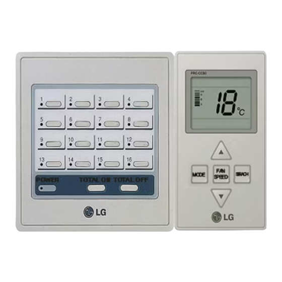
Name of Each Part Name of Each Part Simple Central controller 1. On/Off status display LED (total 16EA) Displays the status of the indoor unit if individual On/Off button is pressed. • Cooling/dehumidification/blowing operation: Green • Heating operation: Orange • Failure of product: Red •... -
Page 7: I Dimensional Drawing
Dimensional Drawing Dimensional Drawing Installation Manual 7... -
Page 8: I System Wiring Drawing
System Wiring Drawing System Wiring Drawing 1. Simple central controller installation case 1. Indoor Unit . . . MAIN PCB <Group Number 1 > CN_REMO PI 485 Function Central controller controller1 Connection of indoor Outdoor unit Master Dip switch unit Connection between master and slave... - Page 9 System Wiring Drawing 2. Simple central controller installation case 2 Communication line can be extended to up to 16 simple central controllers with one serving as master and others as slave. Slave Slave Master Installation method 1. Connect 4 wires to only one remote control from any one outdoor unit. (black lines are Vcc & GND, dotted lines are communication line C &...
- Page 10 System Wiring Drawing 3. Simple central controller installation case 3 Slave Slave Slave Slave Slave Master Installation method 1. Set of three simple central controller are clubbed together in cascade for common power sharing line form the same outdoor. 2. Communication line can be commonly shared among all controllers (dotted lines). 3.
-
Page 11: I Method Of Installation
Method of Installation Method of Installation 1. Hold the front/rear central part of the central controller with the both hands and then separate the case by pulling it ahead or behind while lightly pressing the front case. 2. Loose 4 screws anchoring PCB and then separate the rear case and PCB. - Page 12 Method of Installation 4. Connect connection wires according to the instructions (See page 12) • To take out connecting wires from back Wire hole side of case, use the wire hole on the rear case. Rear Case Wire hole • To take out connecting wires from front sides of case, puncture the dotted spots as shown in the picture and take out the connecting wires out fo it.
-
Page 13: I Method To Connect Wires
Method to Connect Wires Method to Connect Wires 1. Make connection between PI 485 installed on the outdoor unit and central controller. Central controller 2. To supply power to the central controller, supply it from the terminal block Vcc and GND terminal of PI 485 or supply it through a separate DC 10V power supply unit. -
Page 14: I Network Interfce Connection
Select Air Select Network Conditioner Type Type ON KSDO 4H * LGAP : LG Air conditioner Protocol & MPS MULTI Products Configuration Methods ON KSDO4H 1 ON, All others OFF: & MPS Inverter Product + Central Controller (All types) -... -
Page 15: I Method To Set Switch
Method to Set Switch Method to Set Switch Group Setting Select the group using rotary switch in the front of controller PCB for the central controller. Group 11 12 15 16 number Setting of rotary switch Setting of Master/Slave Using dip switch no.1 located in the front of controller PCB, set the relevant central controller as master/slave as per the requirement. -
Page 16: Master/Slave Setting When Applying Lgap
Connection Method of Function Controller Master/slave setting when applying LGAP Select the on/off of dip switch no. 2 located on the front side of the controller PCB to decide whether to apply LGAP or not. Master - When you turn on the dip switch no. 2, the LGAP Master Slave Slave... -
Page 17: Connection Method Of Function Controller
Connection Method of Function Controller Connection Method of Function Controller Power should always be off while connecting function controller to the central controller. Connect the function controller as shown below. Symbols shown as CN_REMO at the terminal block of the central controller and color of cable connecting the function controller must correspond. PQRCHCS0 Central controller Function controller... -
Page 18: I Addressing Of Indoor Unit
Addressing of Indoor Unit Addressing of Indoor Unit Multi V PLUS & MPS Product Using Wired Remote Controller AUTO SWING OPERATION SET TEMP FAN SPEED SUB FUNCTION Room Temp AUTO Heater Preheat Defrost Humidify Filter Out door 1 2 3 4 Time ZONE Timer... - Page 19 Addressing of Indoor Unit Using Wireless Remote Controller 1. Address setting mode 1) Keep pressing upper left side key continuously and press RESET button once. Now the system is ready for address setting. 2) Set the Indoor unit address using the temperature controller buttons. Allowed Range : 00-FF Group No.
-
Page 20: I Troubleshooting
Troubleshooting Troubleshooting 1. Cross check again, if all connection are made as per instructions given in the installation manual. 2. In case, if multi products (Multi-V, MPS, Multi etc.) are connected to the controller (to one network), first finish the settings for all products & only then start the system. 3. - Page 21 Disegno del cablaggio del sistema Disegno del cablaggio del sistema 1. Installazione centralina di controllo semplice caso 1. Indoor Unit . . . principale <Numero del gruppo 1> CN_REMO PI 485 Unità di controllo funzioni Centralina di controllo 1 Connessione dell'unità...
Need help?
Do you have a question about the PQCSB101S0 and is the answer not in the manual?
Questions and answers