
Related Manuals for Micromeritics SediGraph III 5120


Summary of Contents for Micromeritics SediGraph III 5120
- Page 1 ® SediGraph III 5120 Installation Instructions and Checklist 512-42870-02 March 2010...
- Page 2 Windows is a registered trademark of Microsoft Corporation. SediGraph is a registered trademark of Micromeritics Instrument Corporation. Copyright Micromeritics Instrument Corporation, 2010. All rights reserved.
-
Page 3: Table Of Contents
Symbols............................1 Part 1: Installation Instructions ......................2 Preparing for Installation........................2 Equipment Description........................... 3 SediGraph III 5120......................... 3 MasterTech 052 (optional) ......................4 Removing Packing Material and Making Internal Connections ............5 Attaching Tubes and Cables........................9 Installing the 5120 Analysis Program ....................12 Preparing the Analysis Fluids ........................ - Page 4 Table of Contents SediGraph III 5120 Installation Verifying Operation ..........................34 Performing a Reference Material Analysis .................... 35 Running a Long Scan ..........................36 Exceptions .............................. 36 Signatures ............................... 37 Installer............................37 Customer Representative........................ 37 Appendix A: MasterTech Installation ....................38 Removing Packing Material From the Unit ...................
-
Page 5: Introduction
SediGraph III 5120 Installation Introduction Introduction This document describes how to install and verify operation of the SediGraph III 5120. An installation checklist is included following the instructions. Complete each item in the checklist and return the checklist to Micromeritics. -
Page 6: Part 1: Installation Instructions
Preparing for Installation SediGraph III 5120 Installation Part 1: Installation Instructions Preparing for Installation Before you begin installation of the SediGraph III 5120, perform these steps: • Thoroughly review the Preinstallation Checklist, which has been returned from the cus- tomer. -
Page 7: Equipment Description
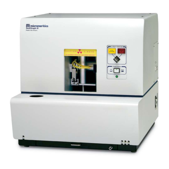
Equipment Description SediGraph III 5120 The SediGraph III 5120 Particle Size Analysis System consists of up to two particle size analyzers, and a multi-function computer. The particle size analyzer is mounted on adjustable feet and contains a level indicator so that accuracy of the analysis process is maintained. It is designed for completely automatic operation;... -
Page 8: Mastertech 052 (Optional)
The MasterTech 052, an automatic sampling device that operates in conjunction with the SediGraph III 5120, is also available. The MasterTech allows you to “queue up” as many as 18 predispersed samples to run consecutively and unattended. It allows samples to be redispersed either by stirring only or by stirring and disruption with an ultrasonic probe. -
Page 9: Removing Packing Material And Making Internal Connections
SediGraph III 5120 Installation Removing Packing Material and Making Internal Connections Removing Packing Material and Making Internal Connections Before operating the SediGraph, remove the internal packing material. Failure to do so may result in damage to the SediGraph. See the drawing #512/10300/00, which was shipped inside of the analysis module, for details 1. - Page 10 Removing Packing Material and Making Internal Connections SediGraph III 5120 Installation 3. Lift up, then remove the fluid module cover. 4. Remove tubes D and E. Tubes D and E 5. Loosen the 6 fluid module retaining screws. Retaining screw...
- Page 11 SediGraph III 5120 Installation Removing Packing Material and Making Internal Connections 6. Pull out the drip tray, then pull the fluid module forward. Fluid module Drip tray 7. Reach up into the analyzer and remove the foam block from under the X-ray lamp.
- Page 12 Removing Packing Material and Making Internal Connections SediGraph III 5120 Installation 8. Remove X-ray shields: a. Loosen the screw on the first section of the X-ray shield, then remove the shield. b. Loosen the two screws on the second section of the X-ray shield, then remove the shield.
-
Page 13: Attaching Tubes And Cables
SediGraph III 5120 Installation Attaching Tubes and Cables 10. Insert the X-ray key: a. The key is taped to the panel to the left of the high voltage supply. Remove the tape. b. Remove the key from the plastic bag and place the key in the X-ray switch c. - Page 14 Attaching Tubes and Cables SediGraph III 5120 Installation 2. Connect an RS232 cable to the connector on the rear panel of the analyzer and to the computer. 3. Connect the power cable to the connector on the rear panel of the analyzer and to a power source.
- Page 15 The installation CD shipped with the analyzer contains the 5120 analysis software. To install the software: 1. Insert the Micromeritics 5120 analysis software CD into your CD-ROM drive. 2. Select Start from the Status bar, then Run from the Start menu.
-
Page 16: Installing The 5120 Analysis Program
Browse 6. If you want to run the Micromeritics software from the desktop, select the checkbox just below the Destination Folder group box to add an icon to the desktop. 7. The Micromeritics software icon is added to the Micromeritics folder by default. If you prefer a different folder, enter or select one from the drop-down list. - Page 17 SediGraph III 5120 Installation Installing the 5120 Analysis Program 9. Click Next ; the Analyzer Configuration dialog is displayed. 10. In the Step 1 group box, click the radio button for the number of analyzers to be attached to this computer.
- Page 18 Installing the 5120 Analysis Program SediGraph III 5120 Installation 13. Click Next. The Calibration File Installation dialog is displayed. 14. Choose one of the following: • If you have only one analyzer attached to the computer, the source location will be the setup CD currently in the CD-ROM drive, which is the default location.
- Page 19 SediGraph III 5120 Installation Installing the 5120 Analysis Program c. Remove the current setup CD and insert the CD containing the calibration files in the CD-ROM drive. d. When the CD drive light stops blinking, press Finish e. The files are loaded, then this message is displayed:...
- Page 20 Installing the 5120 Analysis Program SediGraph III 5120 Installation 16. The Installation Complete dialog box is displayed.. 17. Click Finish to close the dialog. 18. Remove the Setup CD and store in a safe place. The original Setup CD contains calibration files specific to your instrument.
-
Page 21: Preparing The Analysis Fluids
SediGraph III 5120 Installation Preparing the Analysis Fluids Preparing the Analysis Fluids 1. Pour approximately 2 1/2 liters of 0.05% sodium metaphosphate and de-ionized water into the rinse container. 2. Insert the rinse, waste, and overflow tubes into the appropriate container cap, and attach the tube weights. -
Page 22: Installing The Mastertech 052 (Optional)
Installing the MasterTech 052 (Optional) SediGraph III 5120 Installation 6. When the rinse operation is complete, select Unit [n] > Drain and load. 7. Click Continue 8. Fill the mixing chamber with baseline solution when instructed. 9. When the drain and load operation is complete, Unit [n] >Baseline. -
Page 23: Verifying Operation
SediGraph III 5120 Installation Verifying Operation Verifying Operation Verifying SediGraph Operation 1. Select Unit [n] > Show Schematic. Analysis Cell: Arrow indicates Mixing Chamber Cell Pump direction of Stirrer Speed Speed movement Arrows in pumps show flow direction Shown only if a... -
Page 24: Verifying Mastertech Operation (Only If Mastertech 052 Is Installed)
Verifying Operation SediGraph III 5120 Installation 4. To test the X-ray, right-click on the cell icon, then select each of these commands: • X-Ray Intensity Low • X-Ray Intensity Normal 5. To test the cell pump, right click on the cell pump icon, then select: •... - Page 25 SediGraph III 5120 Installation Verifying Operation 7. Make sure the schematic is displayed and manual mode is enabled. Shown only if MasterTech is installed 8. If the arm is in the Load position, press the ARM AUTO/LOAD switch on the front panel of the MasterTech to release it.
- Page 26 This concludes verification of operation of the system. If everything performed as described above, proceed to performing a reference material analysis. If you encountered any problems, refer to Chapter 9 of the SediGraph III 5120 Operator’s Manual for troubleshooting procedures.
-
Page 27: Performing Reference Material Analysis
SediGraph III 5120 Installation Verifying Operation Performing Reference Material Analysis Creating a Sample File 1. Select File > Open > Sample Information. 2. Enter REF <serial number>.SMP for File name. For example: REF101.SMP indicates that this is a test of Reference Material on an analyzer with serial number 101. - Page 28 Verifying Operation SediGraph III 5120 Installation 4. Click Replace All 5. Select cpsrm.smp, then click 6. Enter your name in the Operator field. 7. Click Save, then Close Mar 2010...
-
Page 29: Performing The Analysis
SediGraph III 5120 Installation Verifying Operation Performing the Analysis 1. Select Unit [n] > Sample Analysis. 2. Click , enter the name of the sample file you created in the previous procedure, Browse then click 3. Click Next Mar 2010... - Page 30 Verifying Operation SediGraph III 5120 Installation 4. Make sure the Prepare SediGraph to load sample box is checked and Leave liquid in mixing chamber is selected. 5. Pour approximately 50 mL of 0.05% sodium metaphosphate in water into a beaker.
-
Page 31: Performing A Long Scan
SediGraph III 5120 Installation Verifying Operation Performing a Long Scan 1. Raise the cell to about 100-1500 steps. 2. Make sure the cell if filled with water. 3. Enable the Service Test mode by selecting Options > Service Text Mode. - Page 32 Verifying Operation SediGraph III 5120 Installation 8. Click Replace All, select the file LONGSCAN.SVT, then click 9. In the Test field, change the 12 hour scan to read a 2 hour scan. 10. Enter you name in the Operator field.
- Page 33 SediGraph III 5120 Installation Verifying Operation 12. Select step 2 and click EDIT 13. Change the 720 minutes to 120 minutes, then click 14. Click Save , then Close 15. Select Unit [n] > Service Test > Start. 16. Select the file you just created, then click 17.
-
Page 34: Final Documentation
Service Support Center in Norcross, Georgia, USA. After completing the installation process, representatives of Micromeritics who install instruments are required to send the documents listed below to Micromeritics for inclusion in the customer's instrument history. -
Page 35: Part 2: Installation Checklist
SediGraph III 5120 Installation Checklist Description Part 2: Installation Checklist Checklist Description The tables in the checklist contain the columns described below Column Description/Action Procedure Perform the procedure described in this column. Evaluation Code Circle an evaluation code for each procedure according to the... -
Page 36: Preparing For Installation
Preparing for Installation SediGraph III 5120 Installation Preparing for Installation Evaluation Initial/ Procedure Code Date Review the Preinstallation Instructions and Checklist and ensure that the F N/A laboratory is prepared for installation. Ensure that the required personnel are available. F N/A... -
Page 37: Installing The Analysis Program
SediGraph III 5120 Installation Installing the Analysis Program Evaluation Initial/ Procedure Code Date Insert the air filter in the drip tray. F N/A Level the analyzer. F N/A Place the PUMP CONTROL switch in the AUTO position. F N/A Place the SediGraph power switch in the ON position. -
Page 38: Installing The Mastertech 052 (Optional)
Installing the MasterTech 052 (Optional) SediGraph III 5120 Installation Installing the MasterTech 052 (Optional) Evaluation Initial/ Procedure Code Date Remove the packing material. F N/A Select the line voltage. F N/A Install the fuse(s). F N/A Turn on the MasterTech. -
Page 39: Performing A Reference Material Analysis
SediGraph III 5120 Installation Performing a Reference Material Analysis Performing a Reference Material Analysis Perform a garnet reference material analysis. Record the results listed in the Reference Material Kit in the Expected Results column below and record the analysis results in the Actual Results column. -
Page 40: Running A Long Scan
Running a Long Scan SediGraph III 5120 Installation Running a Long Scan Run a Scan for a minimum of two hours. Record the coefficient of variation below. Evaluation Initial/ Expected Results Actual Results Code Date Coefficient of variation % should... -
Page 41: Signatures
SediGraph III 5120 Installation Signatures Signatures Installer Name: Signed: (please print) Position: Date: Company: Field Service Report (FSR Number): Customer Representative Name: Signed: (please print) Position: Date: Company: Field Service Report (FSR Number): Mar 2010... -
Page 42: Appendix A: Mastertech Installation
Removing Packing Material From the Unit SediGraph III 5120 Installation Appendix A: MasterTech Installation Removing Packing Material From the Unit After removing the MasterTech from the shipping carton, remove all foam packing material from the unit before proceeding with installation. - Page 43 SediGraph III 5120 Installation Selecting the Voltage 3. Pull the voltage selector card straight out of the power connector housing.. 4. Orient the voltage selector card so that the desired voltage is indicated at the bottom. Orient the indicator pin so that it points upward as shown in the following illustration.
- Page 44 Selecting the Voltage SediGraph III 5120 Installation The power cord should be disconnected from the MasterTech when installing or replacing fuses. Failure to do so could result in electrical shock. a. Observe the position of the fuse block, using the previous figure for reference. If the single-fuse arrangement is desired, position the fuse block so that the side with the single-fuse slot and the jumper bar is away from the cover.
-
Page 45: Turning On The Mastertech
SediGraph III 5120 Installation Turning on the MasterTech 7. Insert the fuse block and cover assembly into the input power connector (as shown in the following illustration) and snap it into place. Once the fuse block and cover assembly are in place, the position of the indicator pin shows the input power selected. -
Page 46: Installing The Beaker Tray
Installing the Beaker Tray SediGraph III 5120 Installation Pump Auto/Off Power Display Switch Intensity Control Ultrasonic Probe Arm Auto/Load Auto/On Switch Switch 4. Press the ARM AUTO/LOAD switch on the front panel of the MasterTech. The arm should rise to the Load position, which is used for removal and replacement of the tray. -
Page 47: Connecting Cables
SediGraph III 5120 Installation Connecting Cables Connecting Cables 1. Position the MasterTech next to the SediGraph, making sure that the units are level and their bases are at the same height. Alternatively, the MasterTech may be placed on top of the SediGraph. -
Page 48: Installing The Ultrasonic Probe
Installing the Ultrasonic Probe SediGraph III 5120 Installation Installing the Ultrasonic Probe Make sure that no power is supplied to the unit before starting this procedure. 1. Make sure that the power ON/OFF switch on the rear panel of the MasterTech is in the OFF (O) position. -
Page 49: Installing Sample Transfer Tubing
SediGraph III 5120 Installation Installing Sample Transfer Tubing Installing Sample Transfer Tubing 1. Make sure that the arm is in the Load (uppermost) position. When the arm is in the Load position, the Load LED is illuminated. If the LED is not illuminated, press the ARM AUTO/LOAD switch. - Page 50 Installing Sample Transfer Tubing SediGraph III 5120 Installation 8. Attach the end of another segment of tubing to the Discharge Tube connector on the front of the MasterTech. If the MasterTech is located on top of the SediGraph, use the longer segment of tubing (P/N 052-32802-00).
Need help?
Do you have a question about the SediGraph III 5120 and is the answer not in the manual?
Questions and answers