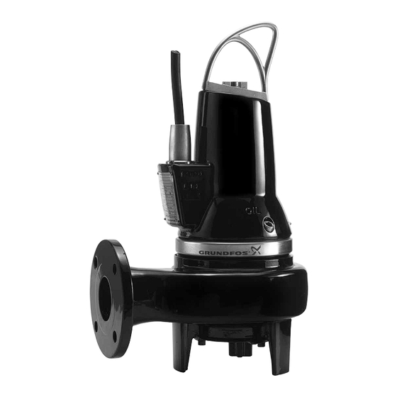
English (GB) Installation and operating instructions Original installation and operating instructions Warning Prior to installation, read these installation CONTENTS and operating instructions. Installation and Page operation must comply with local regulations and accepted codes of good Symbols used in this document practice.
The pumps can be installed on an auto-coupling system or stand freely on the bottom of a pit. Pump housing The pumps can be controlled via the Grundfos LC, 2.2 Applications LCD 107, LC, LCD 108, LC, LCD 110 pump controllers or the Grundfos CU 100 control box.
3. Delivery and handling 2.3 Operating conditions The SL1, SLV pumps are designed for intermittent The pump may be transported and stored in a operation (S3). When completely submerged in the vertical or horizontal position. Make sure that it pumped liquid, the pumps can also operate cannot roll or fall over.
4. Identification 4.1 Nameplate The nameplate states the operating data and approvals applying to the pump. The nameplate is fixed with rivets to the side of the stator housing close to the cable entry. Fit the additional nameplate supplied with the pump close to the pit. Fig.
4.2 Type key Please note that not all combinations are available. Code Example SL 1 50 .65 .11 .EX .2 .1 .5 02 Pump type Grundfos sewage/wastewater pumps Impeller type Single-channel impeller Free-flow impeller (SuperVortex) Pump passage Maximum solids size [mm]...
5. Approvals 5.1 Approval standards The standard versions of SL1 and SLV pumps have been tested by VDE and approved by LGA (notified body under the Construction Products Directive) according to EN 12050-1 or EN 12050-2 as specified on the pump nameplate.
6. Safety 6.1 Potentially explosive environments Use explosion-proof pumps for applications in Warning potentially explosive environments. The use of this product requires experience with and knowledge of the Warning product. The pumps must under no circumstance Persons with reduced physical, sensory or pump combustible or flammable liquids.
We recommend that you always use The guide rails must not have any axial Caution Grundfos accessories to avoid malfuncion Note play as this would cause noise during due to incorrect installation. pump operation.
6. Clean out debris from the pit before lowering the Proceed as follows: pump into the pit. 1. Fit a 90 ° elbow to the pump outlet and connect 7. Fit the guide claw to the pump outlet. the outlet pipe/hose. 8.
3 m free cable above the for this application. They must be maximum liquid level. connected to the Grundfos LC, LCD 108 pump controller via the intrinsically safe Warning LC-Ex4 barrier to ensure a safe circuit.
Wiring diagram for three-phase pumps breaker, such as Grundfos CU 100 control box • a Grundfos LC, LCD 107, LC, LCD 108 or LC, 8.2 CU 100 control box LCD 110 pump controller. The CU 100 control box incorporates a motor- See fig.
They must be Controllers for single-phase pumps incorporate connected to the Grundfos DC, DCD or capacitors. LC, LCD 108 pump controller via an The LC controller is fitted with two or three level...
8.4 Thermal switches 8.5.2 Recommendations Before installing a frequency converter, calculate the All pumps have two sets of thermal switches lowest allowable frequency in the installation in order incorporated in the stator windings. to avoid zero flow. The thermal switch in circuit 1 (T1-T3) will break the •...
9. Starting up the product 9.2 Operating modes The pumps are designed for intermittent operation Warning (S3). When completely submerged, the pumps can Before starting work on the pump, make also operate continuously (S1). sure that the fuses have been removed or the mains switch has been switched off.
See fig. or 6. If the pump is inactive for long periods of Note time, we recommend that you check the function of the pump. Service videos can be found in Grundfos Note Product Center at www.grundfos.com.
A general overhaul of the pump is usually required in case of defective ball bearings or poor motor function. This work must be carried out by Grundfos or a service workshop authorized by Grundfos. Fig. 12 Pump viewed from inlet side...
50). As the impeller is fastened to the shaft end, If the bush is worn and must be replaced, the the impeller will be removed together with the pump must be checked by Grundfos or a service motor part. workshop authorized by Grundfos.
10.5 Oil change Every 3000 operating hours or once a year, change the oil in the oil chamber as described below. If the shaft seal has been changed, the oil must be changed as well. See section 10.4 Checking/ replacing the shaft seal.
If a pump has been used for a liquid which is injurious to health or toxic, the pump will be classified as contaminated. If you request Grundfos to service the pump, contact Grundfos with details about the pumped liquid, etc. before returning the pump for service. Otherwise Grundfos can refuse to accept the pump for service.
11. Fault finding Warning Warning Before attempting to diagnose any fault, All regulations applying to pumps installed make sure that the fuses have been in potentially explosive environments must removed or the mains switch has been be observed. switched off. Make sure that the power Make sure that no work is carried out in supply cannot be accidentally switched on.
0:2006. Insulation class F (155 °C). Pump curves Pump curves are available via www.grundfos.com. The curves are to be considered as a guide. They must not be used as guarantee curves. Test curves for the supplied pump are available on request.
Page 23
Appendix GB: One-pump installation on auto-coupling Eine Pumpe mit automatischer Kupplung SL1.50 SLV.65 Fig. A Pump type Z10a Z12a ZDN1 1 1/2" DN65 1 1/2" DN65...
Page 24
GB: Free-standing installation Freistehender Einbau SL1.50 SLV.65 Fig. B Pump type DC02 DN65 DN65...
Page 28
Descrizione Aprašymas Apraksts Omschrijving Pos. Perno Vielokaištis Tapa Paspen Rivetto Kniedė Kniede Klinknagel Chiavetta Kaištis Atslēga Spie O-ring O žiedas Apaļa šķērsgriezuma blīvgredzens O-ring O-ring O žiedas Apaļa šķērsgriezuma blīvgredzens O-ring O-ring O žiedas Apaļa šķērsgriezuma blīvgredzens O-ring O-ring O žiedas Apaļa šķērsgriezuma blīvgredzens O-ring Statore...
Page 29
Opis Descrição Instalaţie fixă Naziv Pos. Kołek Pino Klin Rebite Zakovica Klin Chaveta Cheie Klin Pierścień O-ring O-ring Inel tip O O-prsten Pierścień O-ring O-ring Inel tip O O-prsten Pierścień O-ring O-ring Inel tip O O-prsten Pierścień O-ring O-ring Inel tip O O-prsten Stator Estator...
Page 34
Argentina China Hong Kong Bombas GRUNDFOS de Argentina S.A. GRUNDFOS Pumps (Shanghai) Co. Ltd. GRUNDFOS Pumps (Hong Kong) Ltd. Ruta Panamericana km. 37.500 Centro 10F The Hub, No. 33 Suhong Road Unit 1, Ground floor Industrial Garin Minhang District Siu Wai Industrial Centre 1619 Garín Pcia.
Page 35
Malaysia Serbia Turkey GRUNDFOS Pumps Sdn. Bhd. Grundfos Srbija d.o.o. GRUNDFOS POMPA San. ve Tic. Ltd. 7 Jalan Peguam U1/25 Omladinskih brigada 90b Sti. Glenmarie Industrial Park 11070 Novi Beograd Gebze Organize Sanayi Bölgesi 40150 Shah Alam Phone: +381 11 2258 740...
Need help?
Do you have a question about the SL1.50 Series and is the answer not in the manual?
Questions and answers