Grundfos SL1 Installation And Operating Instructions Manual
Hide thumbs
Also See for SL1:
- Installation and operating instructions manual (670 pages) ,
- Product manual (156 pages) ,
- Safety instructions (46 pages)

Related Manuals for Grundfos SL1


Summary of Contents for Grundfos SL1
- Page 1 GRUNDFOS INSTRUCTIONS SL1 and SLV pumps 1.1 - 11 kW, 60 Hz Installation and operating instructions...
-
Page 2: Table Of Contents
1. LIMITED WARRANTY Products manufactured by GRUNDFOS PUMPS CORPORATION CONTENTS (Grundfos) are warranted to the original user only to be free of defects in material and workmanship for a period of 24 months Page from date of installation, but not more than 30 months from date LIMITED WARRANTY of manufacture. -
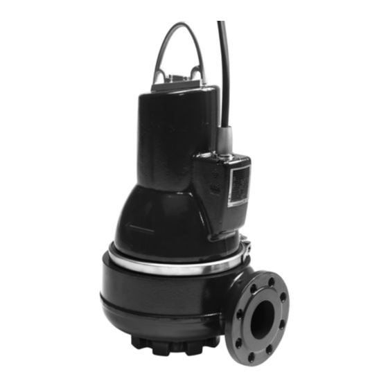
Page 3: Product Drawing
S1 operation S3 operation 3.1 Product drawing Stop levels Fig. 2 pH value SL1 and SLV pumps in permanent installations can be used for pumping liquids with the following pH values: Pump Material Material pH value type variant... -
Page 4: Delivery And Handling
4. Delivery and handling 5. Identification The pump may be transported and stored in a vertical or 5.1 Nameplate horizontal position. Make sure that it cannot roll or fall over. The nameplate states the operating data and approvals applying to the pump. The nameplate is fitted to the side of the stator 4.1 Transportation housing close to the cable entry. -
Page 5: Type Key
5.2 Type key The pump can be identified by means of the type designation stated on the pump nameplate. See section Nameplate. Code Example Pump type Grundfos sewage/wastewater pumps Impeller type ® S-tube impeller SuperVortex (free-flow) impeller Free spherical passage... -
Page 6: Approvals
6. Approvals The SL1 and SLV pumps have been approved by CSA and FM, and the explosion-proof versions hold an FM type examination certificate no.: 3035318. Approval standards These pumps are approved by CSA and FM according to UL778, C22.2 no 108 and FM 3600, FM 3615 and FM 3650. -
Page 7: Potentially Explosive Environments
The maximum current from the control unit must be limited to 350 mA. Installation types The SL1 and SLV pumps are designed for two installation types: • submerged installation on auto-coupling •... -
Page 8: Submerged Installation On Auto-Coupling
10. Adjust the length of the motor cable by coiling it up on a relief 8.1 Submerged installation on auto-coupling fitting to ensure that the cable is not damaged during operation. Fasten the relief fitting to a suitable hook at the top of the tank. -
Page 9: Torques For Suction And Discharge Flanges
Make sure that all protective equipment has been connected correctly. Float switches used in potentially explosive environments must be approved for this application. They must be connected to the Grundfos DC, DCD pump controller via a intrinsically safe barrier to ensure a safe circuit. - Page 10 Pumps without sensor must be connected to this controller type: • a Grundfos DC, DCD pump controller. Pumps with sensor must be connected to a Grundfos IO 113 and the following controller type: • a Grundfos DC, DCD pump controller.
-
Page 11: Wiring Diagrams
9.1 Wiring diagrams The pumps are supplied via either a 7-wire cable or a 10-wire cable. See fig. for wiring diagrams for 7-wire cable connection or figs 7, for wiring diagrams for 10-wire cable connection. For further information, see the installation and operating instructions for the selected pump controller. - Page 12 Standard version Sensor version Thermal switches Thermal switch and PT1000 resistor CSA approved, with/without FM approval Moisture switch and water-in-oil sensor CSA approved, with/without FM approval Wiring diagram, 10-wire cable, Star connected (Y) Fig. 8 Standard version Sensor version Thermal switches Thermal switch and PT1000 resistor CSA approved, with/without FM approval Moisture switch and water-in-oil sensor...
- Page 13 SL voltage concept To standardize and help minimize part numbers and pump versions of the SL product portfolio, Grundfos created the 61J voltage variant. 61J is a tri-voltage (208 V / 230 V / 460 V), three phase, 60 Hz DOL (Direct-On-Line) connected motor.
-
Page 14: Pump Controllers
9.2 Pump controllers 9.4 WIO sensor (water-in-oil sensor) SL1 and SLV pumps can be connected to Grundfos Dedicated The WIO sensor measures the water content in the oil and Controls for level control. Dedicated Controls are available as converts the value into an analogue current signal. The two... -
Page 15: Io 113
9.6 IO 113 9.7 Frequency converter operation IO 113 provides an interface between a Grundfos wastewater All SL1/SLV pump types are designed for frequency converter pump equipped with sensors and the pump controller(s). operation to keep the energy consumption at a minimum. -
Page 16: Start-Up
10. Start-up 10.2 Operating modes The pumps are designed for intermittent operation (S3). Warning When completely submerged, the pumps can also operate Before starting work on the pump, make sure that the continuously (S1). fuses have been removed or the mains switch has S3, intermittent operation: been switched off. -
Page 17: Direction Of Rotation
However, this does not apply to the hydraulic components, such as pump housing, impeller, etc. Warning The cable must only be replaced by Grundfos or a service workshop authorized by Grundfos. Before carrying out maintenance and service, it must be ensured that the pump has been thoroughly flushed with clean water. -
Page 18: Dismantling The Pump
This work must be carried out by Oil filling/venting Grundfos or a service workshop authorized by Grundfos. Warning Defective bearings may reduce the explosion protection. -
Page 19: Assembling The Pump
11.2.3 Removing the seal ring and wear ring 11.3 Assembling the pump Procedure 11.3.1 Tightening torques and lubricants 1. Turn the pump housing upside-down. Torque 2. Knock the seal ring (pos. 46) out of the pump housing using a Pos. Designation Quantity Dimensions Lubricant [Nm] punch. -
Page 20: Oil Quantities
11.3.3 Fitting the seal ring and wear ring 11.4 Oil quantities The table shows the quantity of oil in the oil chamber of SL1 and Procedure SLV pumps. Oil type: Shell Ondina 919. 1. Lubricate the seal ring (pos. 46) with soapy water. -
Page 21: Fault Finding
Impeller blocked by impurities. Clean the impeller. 7. Noisy operation and excessive a) Wrong direction of rotation. Check the direction of rotation and possibly vibrations (SL1). interchange any two of the phases in the incoming supply cable. See section 10.3 Direction of rotation. - Page 22 8. Pump clogged. a) The liquid contains large particles. Select a pump with a larger size of passage. b) A float layer has formed on the surface of Install a mixer in the tank. the liquid. * Applies only to pumps with sensor and with IO 113.
-
Page 23: Technical Data
13. Technical data Pump curves Pump curves are available via the internet on Supply voltage www.grundfos.com. • 3 x 220-277 V - 10 %/+ 10 %, 60 Hz The curves are to be considered as a guide. They must not be •... -
Page 24: Disposal
This product or parts of it must be disposed of in an environmentally sound way: 1. Use the public or private waste collection service. 2. If this is not possible, contact the nearest Grundfos company or service workshop. Subject to alterations. - Page 25 Appendix 1. Exploded drawings...
- Page 27 GRUNDFOS Pumps (Hong Kong) Ltd. Telefax: +64-9-415 3250 Turkey «Порт» Unit 1, Ground floor GRUNDFOS POMPA San. ve Tic. Ltd. Sti. Тел.: +7 (375 17) 286 39 72/73 Siu Wai Industrial Centre Norway Gebze Organize Sanayi Bölgesi Факс: +7 (375 17) 286 39 71 29-33 Wing Hong Street &...
- Page 28 97640162 0315 ECM: 1153489 www.grundfos.com...
Need help?
Do you have a question about the SL1 and is the answer not in the manual?
Questions and answers