Table of Contents
Advertisement
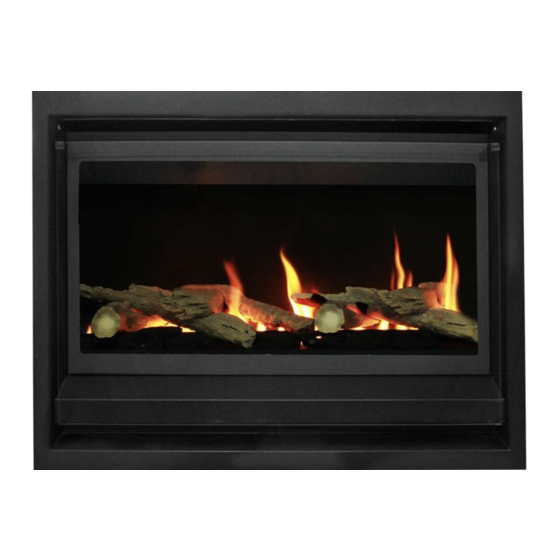
HEATSEEKER
®
GAS FIREBOX
INSTALLATION & OPERATING MANUAL
The Heatseeker Gas Firebox is approved to be installed into a masonary
fireplace and as a zero clearance firebox and is designed to operate on
Natural Gas and Propane (LPG) gases ONLY. Approval Number 6094.
Installed primarily as a decorative appliance. Not certified as a Space Heater.
VERSION 13
Advertisement
Table of Contents

Related Manuals for Real Flame HEATSEEKER 600


Summary of Contents for Real Flame HEATSEEKER 600
- Page 1 HEATSEEKER ® GAS FIREBOX INSTALLATION & OPERATING MANUAL The Heatseeker Gas Firebox is approved to be installed into a masonary fireplace and as a zero clearance firebox and is designed to operate on Natural Gas and Propane (LPG) gases ONLY. Approval Number 6094. Installed primarily as a decorative appliance.
-
Page 2: Important Safety Notice
WARRANTY Provided your Real Flame gas fire is installed in strict accordance with our installation instructions, the firebox is unconditionally guaranteed for ten years and all other parts for twelve months from date of purchase. This unconditional warranty covers part and labour at our discretion taking into consideration normal wear and tear and does not cover fires installed in outdoor settings. -
Page 3: Table Of Contents
Dimensions Heatseeker 600 ..................6 Dimensions Heatseeker 700 ..................7 Dimensions Heatseeker 850 ..................8 Dimensions Heatseeker 1000 ..................9 Dimensions Heatseeker 600 ZC ................10 Dimensions Heatseeker 700 ZC ................11 Dimensions Heatseeker 850 ZC ................12 Dimensions Heatseeker 1000 ZC ................13 Inbuilt Installation Procedure .................14 Zero Clearance Timber Frame Installation ............16... -
Page 4: Data Plate
DATA PLATE (Affixed to burner) MODEL NATURAL GAS UNIT Inj. Size MJ/Hr P .T.P Inj. Size MJ/Hr P .T.P 2 x 2.2 0.8 kPa 2 x 1.1 2.6 kPa 600 & 700 2 x 2.5 0.63 kPa 2 x 1.2 2.55 kPa 850 &... -
Page 5: Inbuilt Model Installation Diagrams
HEATSEEKER INBUILT MODEL • Unit installed into an existing “working” fireplace requires an AGA approved 225mm gas cowl and chimney plate fixed to the chimney top. • If the fireplace is not a “working” fireplace, then the applicable flue to the model being installed should be installed using a gather, single skin flue and AGA approved gas cowl. -
Page 6: Dimensions Heatseeker 600
DIMENSIONS Heatseeker 600 Heatseeker 600 Trim FRONT - 4 SIDED FRONT - 3 SIDED... -
Page 7: Dimensions Heatseeker 700
DIMENSIONS Heatseeker 700 Heatseeker 700 Trim FRONT - 4 SIDED FRONT - 3 SIDED... -
Page 8: Dimensions Heatseeker 850
DIMENSIONS Heatseeker 850 Heatseeker 850 Trim FRONT - 4 SIDED FRONT - 3 SIDED 1040... -
Page 9: Dimensions Heatseeker 1000
DIMENSIONS Heatseeker 1000 1130 1005 Heatseeker 1000 Trim FRONT - 4 SIDED FRONT - 3 SIDED 1190 1140... -
Page 10: Dimensions Heatseeker 600 Zc
DIMENSIONS Heatseeker 600 ZC Heatseeker 600 ZC Trim FRONT - 4 SIDED FRONT - 3 SIDED... -
Page 11: Dimensions Heatseeker 700 Zc
DIMENSIONS Heatseeker 700 ZC Heatseeker 700 ZC Trim FRONT - 4 SIDED FRONT - 3 SIDED... -
Page 12: Dimensions Heatseeker 850 Zc
DIMENSIONS Heatseeker 850 ZC Heatseeker 850 ZC Trim FRONT - 4 SIDED FRONT - 3 SIDED 1040... -
Page 13: Dimensions Heatseeker 1000 Zc
DIMENSIONS Heatseeker 1000 ZC 1130 1075 Heatseeker 1000 ZC Trim FRONT - 4 SIDED FRONT - 3 SIDED 1190 1140... -
Page 14: Inbuilt Installation Procedure
HEATSEEKER INBUILT MODEL Heatseeker Inbuilt Installation Procedure TICK BOXES Check chimney for correct venting of fumes Position unit centrally Connect to gas supply using 15mm copper union Connect to power supply Assemble log and coal or pebble set as shown (Figures 1-7). Figure (1) Remove box containing logset, and Figure (2) Place the 14 large coals and 8 small coals... - Page 15 (continued) The Heatseeker Gas Firebox (Natural Gas Only) is approved for use with Pebbles. To install the Pebbles, follow the installation instructions as per Figures 5-7. Note: A Real Flame Pebble Tray needs to be ordered for this option. Figure (5) Install the metal angle at the rear of...
-
Page 16: Zero Clearance Timber Frame Installation
HEATSEEKER ZERO CLEARANCE MODEL Heatseeker Zero Clearance Timber Frame Installation (Recommended only) (Recommended only) IMPORTANT Install unit and fluing before plasterboard. Plaster to run beyond stud and behind trim HEATER From hearth TRIM Approx 20mm for hearth if required. Frameout Dimensions (in mm) MODEL NOTE: If fire is to be installed off the floor with a 4 sided trim, use the same A, B, C and D dimensions as shown with... -
Page 17: Zero Clearance Model Components
HEATSEEKER ZERO CLEARANCE MODEL Position the Heatseeker firebox in the selected installation position in the room. You will require the Zero Clearance Kit to suit the Heatseeker model you are fitting. This should be fitted to the firebox as shown on page 10. Components ZERO CLEARANCE KIT COMPONENTS No. -
Page 18: Zero Clearance Model Assembly
HEATSEEKER ZERO CLEARANCE MODEL Fit Zero Clearance Kit to unit as shown below: ITEM 8 ITEM 7 ITEM 7 ITEM 6 ITEM 1 Place main fire box (Item 1) Secure side strips (Item 7) and Secure gather centrally on base panel and top strip (Item 8) to main fire (Item 6) to main secure. -
Page 19: Zero Clearance Model Installation Procedure
HEATSEEKER ZERO CLEARANCE MODEL Heatseeker Zero Clearance Installation Procedure TICK BOXES Connect to gas supply Connect to power supply Install flue to 600mm minimum above roof line. (Min. total flue run 3.6m) Plaster to unit with trim removed Install trim Assemble unit as per page 18 Test the unit for safe operation and show customer correct operating procedures. -
Page 20: Lighting Instructions
LIGHTING PILOT AND MAIN BURNER Before lighting the pilot make sure that the gas line is connected. FOR YOUR SAFETY READ BEFORE LIGHTING The appliance has a pilot which must be lit using the piezo ignition, when lighting the pilot follow the instructions exactly. -
Page 21: Commissioning
COMMISSIONING PROCEDURE Once the fire is installed and operational the installer must check for spillage. Carry out the lighting procedure and turn the fire to high. Allow to warm up for 10 minutes and then using a smoke match set 25mm down and 25mm inside of the fire opening run the match across the width of the opening to check that all of the smoke is drawn away. -
Page 22: Optional Power Flue
FAN FAILURE SENSING DEVICE All Real Flame Power Flue systems are fitted with a sensing device within the unit to ensure that, in the event of flow failure, the safety shut off valve within the module will go into lockout and shut off the gas supply to the unit. -
Page 23: Installation
OPTIONAL POWER FLUE (continued) Installation Instructions (continued) LOCATION OF FLUE TERMINAL FOR POWER FLUE Listed below are the minimum clearances required for fan-assisted terminations: Below eaves, balconies and other projections............200mm From the ground, above a balcony or other surface..........300mm From a return wall or external corner................300mm From a Gas meter. - Page 24 SERVICING OF THE POWER FLUE MOTOR The Real Flame Power Flue motor is designed so as to make servicing the motor a simple task. The power lead connected to the motor is to be disconnected (unplugged) and the two side clips are to be undone, the fan motor will then lift out for servicing.
-
Page 25: Motor Clearance
OPTIONAL POWER FLUE (continued) Motor Clearance Minimum clearance 250mm Ensure there is adequate ventilation within this cavity to prevent motor over- heating. 150mm/200mm twin skin flue - optional for additional height Minimum height... -
Page 26: Frameout
OPTIONAL POWER FLUE (continued) For Heatseeker 600, 700 & 850 Series Frameout Minimum clearance IMPORTANT 250mm Install unit and fluing before plasterboard. 400mm x 400mm Access Panel 90mm x 38mm ON EDGE Sound check plaster board Motor Motor MODEL 1800... -
Page 27: Internal Motor
OPTIONAL POWER FLUE (continued) Internal Motor 500mm Top Termination 300mm min. 150mm x 200mm flue extension 200mm Access Panel Min. Distance Domestic: 220mm Motor Industrial: 320mm Termination 150mm x 200mm twin skin flue (if required) Baffle 900mm Heater 25mm Flue Minimum 25mm clearance from outer flue to combustible interior. -
Page 28: External Motor
OPTIONAL POWER FLUE (continued) External Motor 25mm clearance 200mm 340mm External Motor 150mm x 200mm flue extension 150mm x 200mm twin Miniumum skin flue (if required) 1290mm Baffle 900mm Heater NOTE: Maximum of 4 elbows, 45° or 90°. Fan Box Dimensions... -
Page 29: Wiring Diagram
Pressure Power Switch Double Block Solenoid Parts List PART No. DESCRIPTION Dungs BM.740-007 double block solenoid valve Dungs DGAI.73 Module 5.1.3. Electronic Ignition Sparker Electronic Flame Sensor Ecofit 2GTA35 Motor. Complete with ‘sail’ switch. 900mm Real Flame Power Flue Muffler. -
Page 30: Troubleshooting Electronic Ignition And Power Flue System
TROUBLE SHOOTING FOR ELECTRONIC IGNITION AND POWER FLUE SYSTEM. Symptom Possible Cause Corrective Action Fire turned on and No Power to Module Connect Power nothing happens Fire turned on and Pressure switch not Check pressure switch motor starts but operating there is no spark Fire sparks when A. - Page 31 TROUBLE SHOOTING FOR ELECTRONIC IGNITION AND POWER FLUE SYSTEM. (continued) The power flue and electronic control box have a red LED light that indicates the possible cause of a problem, the LED light will flash in different sequences for different problems, the most common are:- Long Flash Short Flash Normal Running State.
-
Page 32: Parts List
PARTS LIST PART No. DESCRIPTION PART No. 1/2˝ to 3/8˝ Hex Nipple BM 733 Control Valve Regulator SC-75 5/16˝ 90O Union Elbow S.I.T. ODS Pilot Assembly (Natural Gas) 1/4˝ Nut and Olive Injector Holder Stem S.I.T. ODS Pilot Assembly (Propane Gas) Injector 1/2˝... -
Page 33: Flue Termination (Cowls) Regulations
HEATSEEKER FLUE TERMINATION (COWLS) REGULATIONS Natural Draught Refer to Note 1 Refer to Note 1 A OR B 600mm AREA CLEARANCE REQUIRED Horizontally from a neighboring structure............1000mm If less than a meter horizontally from a neighboring structure then terminates above that structure by............500mm From any opening into a building..............1500mm From another flue terminal. -
Page 34: Marble Trim Installation Instructions
OPTIONAL MARBLE HEARTH AND/OR MARGIN SET 1190mm 275mm 620mm 270mm 375mm 1810mm Marble Margin Set Installation Procedure Install Heatseeker with trim in place. Install marble over trim up to the fire opening. Use liquid nails to fix to wall. Marble should look like the diagram below once it has been installed and before mantelpiece has been attached. -
Page 35: Mantlepiece Installation Instructions
OPTIONAL MANTELPIECE INSTALLATION Wall Stud Firebox Trim Marble Margin Mantel Leg Mantel Shelf (Internal (Internal Dimension) Dimension) MANTELPIECE DIMENSIONS Federation Square 1440 1340 1165 Adelaide Federation 1460 1300 1170 Windsor Universal 1810 1665 1180 1090 Bouvier Universal 1810 1665 1180 1090 Kensington Universal 1810... -
Page 36: Electrical Diagram
ELECTRICAL DIAGRAM Low/Red Active/ Brown 3-pin plug High/White Common/ Earth/Green Blue Common/Black Motor Switch 2 Pole 3 Position... -
Page 40: Real Flame Contact Information
REAL FLAME PTY LTD ABN 76 006 311 155 Head Office/Factory/Showroom 1340 Ferntree Gully Rd. Scoresby Vic 3179 Ph: (03) 8706 2000 Fax: (03) 8706 2001 E-mail: info@realflame.com.au Richmond - VIC Showroom 300 Swan St. Richmond Vic 3121 Ph: (03) 9428 4443 Fax: (03) 9428 4445 Geelong - VIC Showroom 1/2A Gordon Avenue.
Need help?
Do you have a question about the HEATSEEKER 600 and is the answer not in the manual?
Questions and answers