Real Flame VEKTOR 1100 Installation And Operation Manual
Hide thumbs
Also See for VEKTOR 1100:
- Installation & operating manual (56 pages) ,
- Installation & operating manual (51 pages)
Table of Contents
Advertisement
Quick Links
S C A N F O R T H E
L A T E S T V E R S I O N
V E K T O R 110 0 & 9 0 0 S P A C E H E A T E R
I N S T A L L A T I O N A N D O P E R A T I O N S M A N U A L
The Real Flame Vektor space heater is suitable to be installed into a frame out installation.
1 100 is designed to operate on Natural gas.
900 is designed to operate on Natural gas, LPG and ULPG.
Approval no. GMK 10622
Consumer safety information: please read this manual before installing and operating this appliance.
Failure to follow these instructions may result in a possible fire hazard and/or injury and will void the
warranty.
Ve rsi on X 2
A L L F L U E C O N F I G U R A T I O N S
Advertisement
Table of Contents

Related Manuals for Real Flame VEKTOR 1100


Summary of Contents for Real Flame VEKTOR 1100
- Page 1 I N S T A L L A T I O N A N D O P E R A T I O N S M A N U A L The Real Flame Vektor space heater is suitable to be installed into a frame out installation.
-
Page 2: Table Of Contents
C O N T E N T S WELC OME S PE CIFICAT IONS O P E R A T I O N I N S T R U C T I O N S USER INST R U C TIO NS WiFi D EV IC E C ON T R O L I N ST R U C T I O N S TR OUB LESHO OT I NG F O R YO U R F I R EP LACE I N S T A L L A T I O N I N S T R U C T I O N S... -
Page 3: Welc Ome
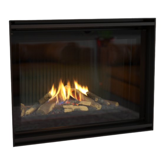
W E L C O M E Congratulations on your selection of the Vektor fireplace. The campfire style fire and the ember glow is designed to enchant you with its elegant flame patterns along with the cutting edge trim that creates a premium finish to this mesmerising fireplace.We hope you create endless memories in front of this warm and cosy fireplace. -
Page 4: Installat Io N In St R U C T I On
I MP OR TAN T SA FE T Y NOT ICE Do not place articles on or against this appliance. Do not use or store flammable materials in or near this appliance. Do not spray aerosols in the vicinity of this appliance whilst it is in operation. Care must be taken to ensure that any return air register or exhaust system does not adversely affect the operation of the appliance or draught of chimney or flue. -
Page 5: S Pe Cificat Ions
S P E C I F I C A T I O N S O F V E K T O R 9 0 0 Appliance Type High Efficiency Gas Fireplace Star Rating Up to 4.7 stars Maximum Heating Output Up to 7.2 kW Heats Room up to Up to 1 10 m... - Page 6 S P E C I F I C A T I O N S O F V E K T O R 110 0 Appliance Type High Efficiency Gas Fireplace Star Rating Up to 4.3 Maximum Heating Output Up to 10.6 kW Heats Room up to Up to 150 m Gas Type...
-
Page 7: O P E R A T I O N I N S T R U C T I O N S
O P E R A T I O N I N S T R U C T I O N S Page... -
Page 8: User Inst R U C Tio Ns
U S E R I N S T R U C T I O N S • Do not operate if you smell gas. Turn appliance off, to light the fire. extinguish any open flame. Contact your installer or a licensed gasfitter. - Page 9 P ro gram mi ng • When the fire shuts off on auto mode or is shut off Each day of the week can be programmed individually in manual mode, the room air fan will continue to for 4 periods P1, P2, P3 and P4, making a total of 28 operate for 8 minutes.
- Page 10 similarly, using button. continually turn on and off. Press ‘OK’ to accept. • If leaving the house for an extended period, the RF Se t t in g t he t em p era t ure thermostat should be turned “OFF”. The temperature setting will now flash.
-
Page 11: Wifi D Ev Ic E C On T R O L I N St R U C T I O N S
WiFi module connected. St ep 2 Download the Real Flame Fire MKII App from the App store or play W iF i S et -u p store if you’re an Android user. From Factory settings the Fireplace will broadcast an... - Page 12 S te p 3 St ep 5 Open the App and click on Set up if you are a new user and have not Go to the WiFi setting on your phone and select your fireplace when established connection to your fireplace prior to this. the device prompts you to choose a network.
- Page 13 St ep 7 S tep 9 Once the fireplace is connected click on the information button and Congrats you have connected to the fireplace. Sit back, relax and select auto join for ease of connection in the future. increase or decrease the temperature as you please. S te p 8 S tep 10 Open the App and click on NO when this pops up.
- Page 14 S e t t i n g re m o t e a c c e ss S te p 11 f i re p l a c e Click OK when the option to rename appears and input the new (eg: Using the phone or tablet remotely to activate the fire when not name.
- Page 15 S te p 14 S tep 15 Subject to operating system the following should occur - Once the Clicking Yes will open the registration section which once completed connection is established, the system will transport you to the screen will allow you to access your fireplace from anywhere. Put in the below.
- Page 16 P u sh i n g t he Fi re p l a c e t o a di f f e re n t St ep 17 ho m e or l o c a l n e t wo rk a f t e r i n i ti a l Using device turn off fireplace.
- Page 17 AN DRO ID D EVICE I NST RUCT IO NS S te p 1 Ste p 3 Open Google play store on your device and search for the ‘Real Before you open the Fireplace app, open your WiFi setting and Flame Fire MKII”...
- Page 18 S te p 5 St ep 8 Once you click yes, this screen will appear. You have to now connect Once you open the app once again, you’ll get a prompt to control the fireplace to your WiFi network. Select your network and enter the your fireplace remotely.
- Page 19 Ste p 12 S te p 10 To rename the fireplace and personalise it, go to settings and rename You can now access your fireplace remotely without the need to as per your liking. connect to your personal WiFi network. S te p 11 Now you can regulate the temperature of the fireplace as per your liking.
-
Page 20: Tr Oub Lesho Ot I Ng F O R Yo U R F I R Ep Lace
T R O U B L E S H O O T I N G F O R Y O U R F I R E P L A C E P rob le m Possi bl e Cause Sugg ested Solution When the remote is activated nothing Power supply is turned off or Remote Reprogram the remote to the receiver... -
Page 21: I N S T A L L A T I O N I N S T R U C T I O N S
I N S T A L L A T I O N I N S T R U C T I O N S Page... -
Page 22: Unit D Im Ensi On S
U N I T D I M E N S I O N S GAS INLET HOLE UNIT V900 1091 545 237 1091 1040 1098 V1 100 1 101 1291 645 1291 1240 1248 UNIT V900 1070 V1 100 1220 Page... -
Page 23: Minimum Fr A Meou T Di Men S I On S
M I N I M U M F R A M E O U T D I M E N S I O N S P I N E F R A M E V I E W 600MM min depth of frameout without cladding U N IT V9 0 0... - Page 24 M I N I M U M F R A M E O U T D I M E N S I O N S P I N E F R A M E W I T H A P P L I A N C E 50mm min clearance required for exhaust flue DETAIL D Wall termination cutout 300m x 460mm high...
- Page 25 M I N I M U M F R A M E O U T D I M E N S I O N S M A N T L E I N S T A L L A T I O N C L E A R A N C E 200 max 1000mm clearance in...
-
Page 26: Installing El Ec Tr I C Eq U I Pmen T A B Ove Firep Lace
I N S T A L L I N G E L E C T R O N I C E Q U I P M E N T A B O V E Y O U R F I R E P L A C E Electronics can be installed in this Zone.* Keep clear of electronics... -
Page 27: Installat Io N In St R U C T I On S
I N S T A L L A T I O N I N S T R U C T I O N S LO C AT IO N Select a location where the fire can be supervised during Test for gas leaks prior to operating appliance. operation. - Page 28 F L U E TE RMI NATIO N LO CATIONS This section is used to determine where your Balanced Flue termination will be located. Flue terminations shall not be recessed in walls or sidings. E XT R EM ELY I MPO RTANT •...
- Page 29 V E K T O R 9 0 0 0 - 5 M F L U E C O N F I G U R A T I O N ( N G & L P G ) 0 - 3 M F L U E C O N F I G U R A T I O N ( U L P G ) V E K T O R 110 0 0 - 5 M F L U E C O N F I G U R A T I O N ( N G ) S E C T I O N C O N T E N T S...
-
Page 30: Ex T Er Nal Wa L L Mo U N Ted Fa N M Odule In Stall Atio N
E X T E R N A L W A L L M O U N T E D F A N M O D U L E I N S T A L L A T I O N 75 mm Aluminium flexi tube (air intake pipe). - Page 31 S e t up wit h ext er nal wall mou nted fa n Apply an 8mm silicon t e r m in al bead fully around the Maximum flue length of 5m for NG & LPG, 3m for ULPG inside of the flue end (heater connection end) Fit flue clamp over flue...
- Page 32 Cut flue exhaust tube (hot tube) length Feed air intake flue pipe (Approximately flush with through location spigot wall exit). Connection and fit retaining screw. plate will sit against wall. Mount flue terminal to Cut Air intake flue. wall. Ensure ends are burr free and round, test fit flue will slide over connection.
-
Page 33: Int E Rna L Fan A N D Wa L L Ter M I N Ati On In Sta Llat Io N
I N T E R N A L F A N A N D W A L L T E R M I N A T I O N I N S T A L L A T I O N Inline fan module NOTE- V1100 IS ONLY AVAILABLE IN NG (ALL FLUE CONFIGURATIONS) - Page 34 Se t u p wi t h in t er na l f an modul e with w a l l Cut tube to length where t e r mi n at i on – appl ian ce mo un ted required.
- Page 35 Slide flue onto connection spigot fully. Tighten clamp fully. Wipe excess silicon, visually check connection to ensure connection is fully sealed. Repeat for connection to underside of fan module. 6. Connect power lead to fan module. Ensure lead is clipped support where Repeat for air intake flue...
- Page 36 Locate terminal on wall and predrill mounting holes where required. Cut flue exhaust tube (hot tube) to length (Flue must extend a minimum of 50mm past the exit face of wall.) It is recommended that the tubes are cut slightly longer and pushed back into wall upon fixing of wall terminal.
-
Page 37: Int E Rna L Fan A N D R O O F Ter M I N At I On
I N T E R N A L F A N & R O O F T E R M I N A T I O N Inline fan module S/S Rooftop Termination Through roof with decktite or similar (not supplied) outer flue 127mm outside diameter 75 mm Aluminium flexi tube (exhaust pipe). - Page 38 Se t u p w it h i nt ernal f an module w ith ro of to p t e r mi n at i on – mi d f lu e mo unte d Maximum flue length of 5m for NG & LPG, 3m for ULPG Apply an 8mm thick silicon bead fully around heater connection approx.
- Page 39 Slide flue onto connection spigot fully. Repeat for air intake flue Tighten clamp fully. connection. Wipe excess silicon, visually check connection to ensure connection is fully sealed. 5. Connect power lead to fan module. Ensure lead is clipped support where required.
- Page 40 Base Assembly Air Intake Connection Flue Discharge Connection Slide flue onto connection spigot fully. Tighten clamp fully. Wipe excess silicon, visually check connection to ensure connection is fully sealed. Screw or rivet in 3 places to hold in place. I M P ORTAN T - Apply silicon bead between inner connection of cowl and flue pipe to seal...
-
Page 41: Rooftop T Er Mi N Ati O N W I Th Ext Er N A L Moto R
R O O F T O P T E R M I N A T I O N W I T H E X T E R N A L M O T O R V EK TOR 90 0 O N LY, NOT AVA IL ABLE ON VE K TO R 110 0 75 mm Aluminium flexi tube (exhaust pipe). - Page 42 Slide flue onto connection Se t u p w it h ext ernal ro of top ter min a tion spigot fully. Tighten clamp Maximum 5m flue length for NG & LPG, 3m for ULPG fully. Wipe excess silicon, visually check connection to ensure connection is Ro o f to p t erm i nat i on fully sealed.
- Page 43 Connect the fan power cable from the appliance Fit the termination on to the to the termination. access panel and match the rivet holes to rivet the Ensure cable termination to the access clamped only to the intake panel. pipe to secure the cable from hanging loose &...
- Page 44 V E K T O R 9 0 0 5 - 9 M F L U E C O N F I G U R A T I O N ( N G & L P G ) 3 - 7 M F L U E C O N F I G U R A T I O N ( U L P G ) N O T A V A I L A B L E O N V E K T O R 110 0 S E C T I O N C O N T E N T S WA LL MOU NT ED FAN MODU L E...
-
Page 45: Ex T Er Nal Wa L L Mo U N Ted Fa N M Odule In Stall Atio N
E X T E R N A L W A L L M O U N T E D F A N M O D U L E I N S T A L L A T I O N V EK TOR 90 0 O N LY, NOT AVA IL ABLE ON VE K TO R 110 0 75 mm Aluminium flexi tube (air intake pipe). - Page 46 S e t u p wi th ext er nal wa ll mo un ted fa n Recommended Silicon t e r m i n a l – Non-acetic, neutral Maximum flue length of 9m for NG & LPG, 7m for ULPG cure 150°C or higher for V900 temperature rated.
- Page 47 Apply an 8mm silicon bead fully around the inside of the flue end (heater connection end) Fit flue clamp over flue (loosely). Slide flue onto connection spigot fully. Tighten clamp fully. Remove cover from fan terminal. Wipe excess silicon, visually check connection to ensure connection is fully sealed.
- Page 48 Connect power cable connector. Insulation to be fully closed and sealed along length. Fit cable clamp to cable. Bends where practical should be insulated, by Fit front cover. cutting the insulation into segments taping together. Joins taped together using aluminum foil self adhesive tape.
-
Page 49: Int E Rna L Fan A N D Wa L L Ter M I N Ati On In Sta Llat Io N
I N T E R N A L F A N A N D W A L L T E R M I N A T I O N I N S T A L L A T I O N V EK TOR 90 0 O N LY, NOT AVA IL ABLE ON VE K TO R 110 0 Exhaust flue must be insulated using 25mm glasswool pipe insulation as supplied by Glen Dimplex Australia. - Page 50 Se t up wi t h i nt er na l f an mod ul e with w al l t e r m in at ion Maximum flue length of 9m for NG & LPG, 7m for ULPG for V900 N OT E - C RI TI C AL INSTAL L R E QUIR EM E NT Fan module to be installed minimum 2m from appliance.
- Page 51 Apply an 8mm thick silicon bead fully around heater Apply an 8mm silicon connection approx. 10mm bead fully around the from the top. inside of the flue end (heater connection end) Apply an 8mm silicon bead fully around the Fit flue clamp over flue inside of the flue end (loosely).
- Page 52 Connection to wall terminal Feed hot exhaust flue Loose fit connections (wall termination connections) into connection, ensure inserted 50mm. Fit retaining screw from below. Feed intake flue into connection, ensure inserted 50mm. Fit retaining screw from below. Fit flue exhaust insulation Insulated with 25mm foil faces glasswool...
- Page 53 Joins taped together using aluminum foil self adhesive tape. Insulation may be fitted prior and after the inline powerflue fan. Failure to fit insulation on the exhaust flue may result in condensation failures with the appliance. Page...
-
Page 54: Int E Rna L Fan A N D R O O F Ter M I N At I On
I N T E R N A L F A N & R O O F T E R M I N A T I O N V EK TOR 9 00 ON LY, NOT AVAILAB LE O N V EK TOR 110 0 Exhaust flue must be insulated using 25mm glasswool pipe insulation as supplied by Glen Dimplex Australia. - Page 55 Se t u p w it h i nt ernal f an module w ith ro of to p Run flue from appliance t e r mi n at i on – mi d f lu e mo unte d to bottom entry on fan Maximum flue length of 9m for NG &...
- Page 56 Slide flue onto connection spigot fully. Tighten clamp fully. Wipe excess silicon, visually check connection to ensure connection is fully sealed. Repeat for connection to underside of fan module. Repeat for air intake flue 5. Connect power connection. lead to fan module. Ensure lead is clipped support where...
- Page 57 Cut rooftop penetration to length if required. Install in to roof penetration. Install supports for base of penetration kit. Fit flue exhaust insulation Install roof seal (Dektite or similar) Insulated with 25mm foil faces glasswool pipe Connect hot exhaust flue insulation, as supplied by and air intake flue as per Glen Dimplex Australia.
- Page 58 Insulation may be fitted prior and after the inline powerflue fan. Failure to fit insulation on the exhaust flue may result in condensation failures with the appliance. Page...
-
Page 59: Rooftop T Er Mi N Ati O N W I Th Ext Er N A L Moto R
R O O F T O P T E R M I N A T I O N W I T H E X T E R N A L M O T O R V EK TOR 90 0 O N LY, NOT AVA IL ABLE ON VE K TO R 110 0 75 mm Aluminium flexi tube (exhaust pipe). - Page 60 Se t u p w it h ext ernal ro of top ter min a tion On the heater connection Maximum flue length of 9m for NG & LPG, 7m for ULPG end - Fit clamp loosely & for V900 apply silicon inside the pipes.
- Page 61 Fit the access panel to the roof penetration. Use the screw holes fix the access panel to the roof penetration. On the termination end - Fit clamp loosely & apply silicon inside the pipes. Apply an 8mm silicon bead fully around the inside of the flue and on the flue spigot.
- Page 62 Connect the fan power cable from the appliance to the termination. Joins taped together using aluminum Ensure cable foil self adhesive tape. clamped only to the intake pipe to secure the cable from hanging loose & touching the hot flue gases pipe.
- Page 63 P O L Y P R O P Y L E N E F L U E C O N F I G U R A T I O N V E K T O R 9 0 0 9 - 13 . 5 M F L U E C O N F I G U R A T I O N ( N G & L P G ) 7 - 13 .
- Page 64 F L U E TE RMI NATIO N LO CATION P O L Y P R O G E N E R A L I N S T A L L A T I O N This section is used to determine where your flue R E Q U I R E M E N T S termination will be located.
- Page 65 Duravent and other certain clamp styles, 1/4˝ or greater All-thread may be used as an extension. 6. Vertical installations must be supported every 3 meters or less. 7. Elbows and tees are sufficiently supported when a bracket is fixed at the female end of the connected straight section.
- Page 66 Page...
-
Page 67: S Et Up Wit H Exte R N A L Wa L L Mou N T Ed Fa N T Ermin A L
S E T U P W I T H E X T E R N A L W A L L M O U N T E D F A N T E R M I N A L Maximum 13.5m flue length Instructions are in 3 sections 1. - Page 68 I MP OR TAN T IN STAL L AT IO N NOT E S · Flexi flue must be fully extended to length. 5m for exhaust flue of NG / LPG and 3m for ULPG. 2 x 7m for inlet. ·...
- Page 69 IN TA K E P I P E CON N ECTIO N TO APPLIAN CE In t a ke pi p e j oi ne r c o n ne ct i o n Flexi flue is provided for air intake.
- Page 70 Assemble spigot connection plate assembly to wall mounting bracket. (4 screws) Slide each flue halfway onto connection joiner. Tighten clamp fully. Wipe excess silicon, visually check connection to ensure O UTL E T CON N E C TI O N F RO M H E ATE R connection is fully sealed.
- Page 71 Slide flue onto connection Fit flue clamp over flue spigot fully. (loosely). Tighten clamp fully. Slide flue onto connection spigot fully. Wipe excess silicon, visually check connection Tighten clamp fully. to ensure connection is fully sealed Wipe excess silicon, visually check connection to ensure connection is fully sealed.
- Page 72 Po l y P ro t o Pol y Pro flu e c on ne ctio n Verify gasket is sitting correctly. Apply a light soapy water film to the gasket and tube end. Insert pipe fully into end fitting, Pipe will push in smoothly and evenly, should this not occur remove pipe and reset gasket.
- Page 73 Remove cover from fan terminal Assemble spigot Remove main assembly connection plate assembly from rear wall to wall mounting bracket. mounting plate assembly. (4 screws) Remove the 5 screws as shown. (Do not remove fan plate screws) Lift off main fan terminal assembly.
- Page 74 Connect power cable connector. Fit cable clamp to cable. Fit front cover. Page...
-
Page 75: Int E Rna L Fan A N D Wa L L Ter M I N Ati On In Sta Llat Io N
S E T U P W I T H A P P L I A N C E M O U N T E D F A N O R I N L I N E M O U N T E D F A N A N D W A L L T E R M I N A L Maximum 13.5m flue length Instructions are in 3 sections... - Page 76 Apply an 8mm thick silicon bead fully around heater connection approx. 10mm from the top. I MP OR TAN T IN STAL L AT IO N NOT E S Flexi flue is in 7m lengths. A maximum of 2 lengths can Flexi flue must be fully extended to length.
- Page 77 Ai r i nt ake p ip e - In take co nn e ct io n t o w al l mo un te d fa n t e rm in al Ensure ends are burr free and round, test fit flue will slide over connection joiner.
- Page 78 F l ue Ex ha ust C on ne c ti on s - Fit hot e x h a u s t Recommended Silicon – Non-acetic, neutral cure fl ue p ip e from ou tl et t e rm in at io n t o fa n o u t le t 150degc or higher temperature rated.
- Page 79 F l ue Exh aus t Conne ction s - Al umi nu m to Po l y Pro f lu e c onnecti on Ensure ends are burr free and round, test fit flue will fit over connection. Lubricate the Poly pro with water or soapy water.
- Page 80 Po l y P ro t o Poly P ro fl ue con n ectio n Verify gasket is sitting correctly. Apply a light soapy water film to the gasket and tube end. Insert pipe fully into end fitting, Pipe will push in smoothly and evenly, should this not occur remove pipe and reset gasket.
- Page 81 Assemble condensate drain and attach to pipe exiting wall. PVC pressure pipe cement must be used. 40mm PVC pipe must be fitted (not shown) to drain to waste Components supplied loose. 15mm PVC Elbow or 15mm STRAIGHT CONNECTOR 15mm PVC class 18 tube 15mm PVC to 15mm threaded union 15mm to 20mm union 20mm to 40mm union...
- Page 82 R O O F T O P P O L Y P R O P Y L E N E F L U E C O N F I G U R A T I O N V E K T O R 9 0 0 9 - 13 .
- Page 83 F L U E TE RMI NATIO N LO CATION P O L Y P R O G E N E R A L I N S T A L L A T I O N This section is used to determine where your flue R E Q U I R E M E N T S termination will be located.
- Page 84 Duravent and other certain clamp styles, 1/4˝ or greater All-thread may be used as an extension. 6. Vertical installations must be supported every 3 meters or less. 7. Elbows and tees are sufficiently supported when a bracket is fixed at the female end of the connected straight section.
- Page 85 Page...
-
Page 86: S Et Up Wit H Inl I N E Or A P Pl I A Nc E Mo U N T Ed Fa N
S E T U P W I T H I N L I N E F A N M O D U L E Air intake pipe 75mm Aluminium flexi flue Polypro rooftop termination - Total max run: 14m - Max number of bends: 9 Ploypro flue 3"... - Page 87 I NT E RNAL I NLI N E FAN M ODUL E W IT H IN TA KE P I P E CON N E C TI O N TO A P P LI ANC E R O OTO P TERMI NAT IO N –...
- Page 88 In ta ke pi pe j oine r conne ction Slide each flue halfway onto connection joiner. Tighten clamp fully. Wipe excess silicon, visually check connection to ensure connection is fully sealed. I nt ake co n ne ct io n to roo f to p te rm in al Ensure ends are burr free and round, test fit flue Rooftop...
- Page 89 Apply an 8mm thick silicon Repeat for air intake flue bead fully around heater connection. connection approx. 10mm from the top. Fan module outlet Apply an 8mm silicon connection bead fully around the inside of the flue end (heater connection end) Cut tube to length where required.
- Page 90 Apply sealant to flue inner and connector. Apply soapy water to o-ring in Poly Pro flue and dampen surface of connector. Push connector fully into Poly pro end connection. Push both clips over to lock into place. Where remove the catch tab from side of condensate fitting.
- Page 91 NOTE – I ns ta ll at io n DRAINAGE MUST FALL TOWARDS CONDENSATE TRAP LOCATED AT THE END OF THE ALUMINUM FLUE SECTION 1. Pipe lengths may be cut to length. Use an alternative clamp (PPS-PAC/PPS-LBC) for the connection if a locking A P-TRAP MUST BE INSTALLED AS SHOWN tab is removed.
- Page 92 Po ly P ro t o Roof t e rm in atio n Ensure termination is supported. Join Poly flue to rooftop termination Ensure clip is fixed to prevent flue pipes from separating. Support flues. W IR IN G – FLU E T E MPE RAT URE L IM IT ING D EV I C E The flue temperature limiting device is inbuilt into the extension wiring and the flue adapter.
-
Page 93: Commissio Nin G P R O C Edu R E
C O M M I S S I O N I N G P R O C E D U R E O n c e t he f ire is i nst a ll ed : 1. Check for gas leaks 2. -
Page 94: Doo R Removal A N D Fi Tmen T
D O O R R E M O V A L A N D F I T M E N T D O O R R E M O V A L ( R E C O M M E N D E D 2 P E R S O N S ) N O T E - It is recommended that eye protection is worn when handling glass. - Page 95 D O O R F I T M E N T ( R E C O M M E N D E D Remove screws and remove inner door (Use suction cups P E R S O N S ) provided) C hec k doo r g l as s an d s ea l i s s i t t i n g i n f ra m e c or re ct l y.
-
Page 96: Me Dia Instal L Ati O N
M E D I A I N S T A L L A T I O N G E N ER AL I NSTAL L ATIO N NOT E The Vektor 900 and 1 100 have different number of logs. Please refer to the picture below for the media setting of each fireplace. - Page 97 Camp f ire Lo g s et media Ar rang em e nt In st ruc t io n Fit Logs A and B. Log A positively locates onto the left- • Lay campfire media as per the fix arrangement shown hand burner set.
- Page 98 Place Logs C and E as per the fix arrangement shown in the image below. Place Logs F, H and I as per the fix arrangement shown in the image below. (Arrangement for the Vektor 900) Place logs D, F, G, H and I as per the fix arrangement shown in the image below.
-
Page 99: L Ed Lig Ht Ing
L E D L I G H T I N G Media back lighting using LED is available as a factory option (NOTE – Must be placed at time of ordering the appliance) A different version of the remote control and receiver unit is used for the LED option. - Page 100 B U R N E R P R E S S U R E A D J U S T M E N T Burner test point pressures must be set whilst appliance is 1 1. Turn appliance down to minimum rate using remote running.
-
Page 101: Pilot Removal A N D B U R N Er R Epl Ac Emen T
P I L O T R E M O V A L A N D B U R N E R R E P L A C E M E N T T O O L S Remove the mesh media cover plate to gain access to the pilot, spark plug and flame sensor. - Page 102 B U R NER R EMOVAL AND RE PL ACE ME N T Using a 16 and 14mm spanner remove the 2 burner gas tubes Remove screws on the edges of the burner tray to detach the burner and using both your hands carefully lift the burner out.
-
Page 103: Pa Rts L Ist
P A R T S L I S T Pa r ts P i c t u re Valve SIT Pilot assembly- refer gas type Injector Natural gas/LPG- refer gas type ULPG Injector Millenium receiver Millennium remote control Techrite Ignition System LED lights and linking cable LED driver LED Transformer... -
Page 104: Ap Pe Ndix 1- Fl U E Ter Mi N Ati O N
A P P E N D I X 1 - F L U E T E R M I N A T I O N Page... -
Page 105: Ap Pe Ndix 2- W I R I N G Di Ag R A Ms
GLEN DIMPLEX AUSTRALIA PTY LTD - VEKTOR 900 WIRING WARNING - ISOLATE POWER BEFORE SERVICING Tech r it e G as C ont rol M od els - Vektor 1100 GLEN DIMPLEX AUSTRALIA PTY LTD - VEKTOR WIRING WARNING - ISOLATE POWER BEFORE SERVICING... - Page 106 W A R R A N T Y I N F O R M A T I O N The benefits provided to you under the following warranty are in Supplier Name___________________________________ addition to any other rights and remedies available to you under the law.
- Page 107 Website: Telephone: www.realflame.com.au AU: 1300 554 155 www.realflame.co.nz NZ: +64 9 274 8265 Glen Dimplex. All rights reserved. Material contained in this publication may not be reproduced in whole or in part, without prior permission in writing from Glen Dimplex.
Need help?
Do you have a question about the VEKTOR 1100 and is the answer not in the manual?
Questions and answers