Advertisement
Quick Links
INSTALLATION INSTRUCTIONS
PRODUCT SAFETY & LEGAL DISCLAIMER
•
IMPORTANT READ ALL INSTRUCTIONS CAREFULLY BEFORE INSTALLING, FAILURE TO DO SO
MAY CAUSE PERSONAL INJURY OR DAMAGE TO PRODUCT AND/OR PROPERTY.
Review the product package and contents prior to beginning the installation. Take care when
•
opening the packaging and removing items. If a return is needed you will want to return the product in
its original packaging if possible.
This instruction guide is provided as a GENERAL installation guide, some vehicles vary dimensionally
•
and may require additional steps.
Test fit the product on the vehicle prior to any third party modifications and or finishing. The
•
manufacturer and/or distributors do not accept responsibility for third party charges, labor and or
third part replacement modifications. Some modifications may void the factory warranty.
•
Exercise due-diligence when installing this product. The manufacturer and distributors of this product
do not accept any responsibility for vehicle damage or personal injury resulting from the installation of
this product. Careless installation and operation can result in serious injury or equipment damage.
•
This product is for general off-road use. All liability for installation and use rests with the
owner/operator.
INSTALLER: Once installation is complete, please return this guide along with other documentation
•
included in this product back to the consumer for future reference. The manufacturer/distributors of
this product do not guarantee this particular version will be available at a later date.
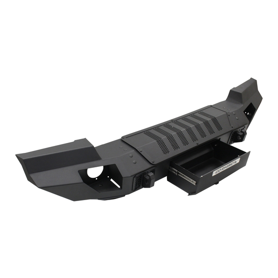
PART NO.
● 230121T
PRODUCT DESCRIPTION:
● TRAILLINE FRONT WINCH
BUMPER-FULL
APPLICATION:
● JEEP WRANGLER JK & JL
Advertisement

Subscribe to Our Youtube Channel
Related Manuals for Go Rhino 230121T


Summary of Contents for Go Rhino 230121T
- Page 1 INSTALLATION INSTRUCTIONS PART NO. ● 230121T PRODUCT DESCRIPTION: ● TRAILLINE FRONT WINCH BUMPER-FULL APPLICATION: ● JEEP WRANGLER JK & JL PRODUCT SAFETY & LEGAL DISCLAIMER • IMPORTANT READ ALL INSTRUCTIONS CAREFULLY BEFORE INSTALLING, FAILURE TO DO SO MAY CAUSE PERSONAL INJURY OR DAMAGE TO PRODUCT AND/OR PROPERTY.
-
Page 2: Installation Instructions
Factory sensors may read shackles or hooks protruding from the fairlead and or tow hooks. • • All sensor testing is completed by Go Rhino Products and or third party testing labs on modified vehicles. Sensor sensitivity, factory sensor housing, orientation, and operating conditions are all variables that •... - Page 3 1/2” x 1 ½” Flange Head Bolt Mesh Cover (Pre-Installed) 1/2” X 1 1/2” Carriage Bolt Gear Drawer (Pre-Installed) Go Rhino recommends you, the installer, read this installation instruction manual from front to back before installing the product. TOOLS NEEDED FOR INSTALLATION: •...
- Page 4 INSTALLATION INSTRUCTIONS Wrangler JL OEM Bumper Removal Step-1 Open the hood and disconnect the vehicle battery or batteries. Step-2 On the passenger side, disconnect the bumper wire harness from the vehicle wire harness, (FIGURE 1). FIGURE 1 Bumper Wire Harness Passenger Side...
- Page 5 INSTALLATION INSTRUCTIONS Step-3 Using an 8mm socket, remove (1) hex bolt on each side of the vehicle securing the air dam to the metal shield behind the air dam, (FIGURE 2). FIGURE 2 Air Dam Hex Bolts...
- Page 6 INSTALLATION INSTRUCTIONS Step-4 Using a slot screwdriver or panel clip removal tool, remove the (8) plastic push pins securing the air dam to the bumper, (FIGURE 3). Remove the air dam from the vehicle. FIGURE 3 Plastic Push Pin Air Dam...
- Page 7 INSTALLATION INSTRUCTIONS Step-5 Using a 16mm socket remove, the (2) hex bolts securing the metal shield to the frame, (FIGURE 4). Remove the metal shield from the vehicle. FIGURE 4 Metal Shield Hex Bolts...
- Page 8 INSTALLATION INSTRUCTIONS Step-6 on each side of the vehicle, use a slot screwdriver or panel clip removal tool and remove (1) plastic push pin securing the frame cover to the frame rail, (FIGURE 5). FIGURE 5 Plastic Push Pin Frame Cover...
- Page 9 INSTALLATION INSTRUCTIONS Step-7 On each side of the vehicle, use an 18mm socket and remove the (2) hex nuts from the studs on each side of the vehicle frame securing the OEM front bumper to the frame, (FIGURE 6 & 7). Driver Side (outer) FIGURE 6 Hex Nuts...
- Page 10 INSTALLATION INSTRUCTIONS Step-8 With assistance remove the OEM front bumper from the vehicle. Step-9 On each side of the vehicle. drill the OEM bumper mounting bracket holes to 1/2“, (FIGURE 8). FIGURE 8 OEM Bumper Mounting Brackets...
- Page 11 INSTALLATION INSTRUCTIONS Wrangler JK OEM Bumper Removal Step-1 Open hood and disconnect the vehicle battery or batteries. Step-2 Begin by using a slotted screwdriver, pry and remove the (4) plastic push pins securing the front of the air dam to the bottom of the factory bumper, (FIGURE 1 & 2). FIGURE 1 Air Dam Plastic Push Pin...
- Page 12 INSTALLATION INSTRUCTIONS Step-3 Remove the (2) plastic pushpins securing the rear of the air dam to the frame cross member, and remove the air dam from the underside of the vehicle, (FIGURE 3). FIGURE 3 Plastic Push Pin Plastic Push Pin Air Dam...
- Page 13 INSTALLATION INSTRUCTIONS Step-4 If equipped, disconnect the wiring harness from the fog lights and unclip the cable ties securing the wiring harness to the factory bumper, (FIGURE 4 & 5). FIGURE 4 Wire Harness FIGURE 5 Cable Tie...
- Page 14 INSTALLATION INSTRUCTIONS Step-5 On each side of the vehicle, remove the (4) hex nuts from the studs securing the factory bumper to the frame using an18mm socket, (Figure 6 & 7). Note: Remove (4) backing plates behind the nuts and save for installation with supplied frame brackets. FIGURE 6 Hex Nuts Backing Plate...
- Page 15 INSTALLATION INSTRUCTIONS Step-6 With assistance remove the factory bumper from the vehicle and set aside. Step-7 Using a Phillips screwdriver remove the (2) fastener securing the frame cover to the top of the frame, (FIGURE 8 & 9). Remove the cover from the vehicle. FIGURE 8 Plastic Push Pin FIGURE 9...
- Page 16 INSTALLATION INSTRUCTIONS Step-8 Using a 10mm socket remove the (2) screws securing the vacuum canister to the frame bracket. Lift and rotate the canister clockwise 180 degrees, then place (1) 3/8” hex nut under each of the canisters mounting flanges and reinstall, and tighten the screws, (FIGURE 10 & 11). Vacuum Canister Screws FIGURE 10 Driver Side...
- Page 17 INSTALLATION INSTRUCTIONS Trailline Bumper Installation JL & JK Step-1 Position the passenger side frame bracket up to the end of the frame, align the holes in the frame bracket with the holes in the frame and secure the frame bracket to the frame using (4) ½” X 1 ½” carriage bolts, (4) ½” flat washers, (4) ½”...
- Page 18 INSTALLATION INSTRUCTIONS Step-2 If equipped, remove the fog lights from the OEM bumper. Step-3 From the back of the Trailine front winch bumper, position one of the factory fog lights so the top of the lens aligns with notch and the lens protrudes out through the opening in the fog light mounting plate, (FIGURE Step-4 Assemble and attach the fog light housing to the fog light mounting plate using (3) of the offset mount clips (3) ¼”...
- Page 19 INSTALLATION INSTRUCTIONS Step-5 The pre-installed mesh front covers need to be removed using hand tools to slowly remove the screws, (FIGURE 4). Using an air assisted impact or ratchet will damage the screw threads and the internal nut assembly in the bumper shell. Use of an appropriate anti-seize compound is highly recommended for re-installation. FIGURE 4...
- Page 20 INSTALLATION INSTRUCTIONS Step-6 With assistance lift the Trailline front winch bumper up to the vehicle, align the holes in the face of the bumper with the weld nuts on the frame brackets and secure the bumper to each frame bracket using (4) ½” x 1 1/2”...
- Page 21 INSTALLATION INSTRUCTIONS Step-8 Reconnect the OEM fog lights to the vehicle wiring harness, and reconnect the battery or batteries. Remember to check and retighten all nuts and bolts periodically. WARNING Do not operate vehicle with tool drawer in unlocked position. Tool drawer must be securely closed and locked.
Need help?
Do you have a question about the 230121T and is the answer not in the manual?
Questions and answers