Advertisement
Quick Links
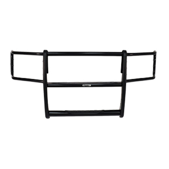
PART NO. 3128MB & 3128MC 2009/2013 DODGE RAM 1500 2/4WD
Do not attempt to install this product on any vehicle other than the one it is designed for and listed
Do not attempt to install this product on any vehicle other than the one it is designed for and listed
Do not attempt to install this product on any vehicle other than the one it is designed for and listed above!
Do not attempt to install this product on any vehicle other than the one it is designed for and listed
QTY
QTY
QTY
QTY
PART DESCRIPTION
4
¼" x 1" button head bolt
8
5/16" x 1" button head bolt
8
5/16" lock nut
8
3/8" x 1 1/4" button head bolt
4
3/8" x 1 1/4" hex bolt
8
3/8" lock washer
4
3/8" hex nut
4
3/8" flat washer
8
5/16" flat washer
Read the assembly and installation instructions completely before you begin.
Read the assembly and installation instructions completely before you begin.
Read the assembly and installation instructions completely before you begin.
Read the assembly and installation instructions completely before you begin.
This installation requires cutting the bumper air dam.
This installation requires cutting the bumper air dam.
This installation requires cutting the bumper air dam.
This installation requires cutting the bumper air dam.
Step 1.
Step 1. Begin the assembly by laying the components out on a protective surface.
Step 1.
Step 1.
Step 2. Position the grille guard side plates with the front edge down and the top and bottom step tube
Step 2.
Step 2.
Step 2.
between the side plates.
Step 3. Attach the top tube to the side plates using (2) 3/8" x 1 1/4" hex bolts and lock washers. Do not tighten.
Step 3.
Step 3.
Step 3.
Step 4. Attach the step tube to the side plates using (4) 3/8" x 1" button head bolts. Do not tighten.
Step 4.
Step 4.
Step 4.
Step 5. Position the center plate between the grille guard side plates, with the slotted holes
Step 5.
Step 5.
Step 5.
down. Attach the center plate to the side plates using (4) 3/8" x 1" button head bolts, flat washers, lock
washers and hex nuts. Do not tighten.
Step 6. Align the grille guard, and tighten only the center plate and step tube nuts and bolts.
Step 6.
Step 6.
Step 6.
Do not tighten the top tube.
Do not tighten the top tube.
Do not tighten the top tube.
Do not tighten the top tube.
Begin the installation. After completing steps 1-9 of the installation, refer to the assembly instructions
diagram to attach the brush guards and head light protectors.
3000 SERIES STEPGUARD
3000 SERIES STEPGUARD
3000 SERIES STEPGUARD
3000 SERIES STEPGUARD
COMPLETE GRILLE & BRUSH GUARD
ASSEMBLY INSTRUCTIONS
PARTS LIST
QTY
QTY
QTY
QTY
2
1
1
1
1
1
1
1
Assembly
Assembly
Assembly
Assembly
PART DESCRIPTION
31283AA side plate
3218P passenger brush guard
3218D driver brush guard
D6P passenger head light protector
D6D driver head light protector
ST3934 3" x 39 ¾" bottom step tube
31288AA 2" x 39 ¾" top tube
CP3934L 39 ¾" center plate
slotted holes in the center plate
slotted holes
slotted holes
above!
above!
above!
Advertisement

Subscribe to Our Youtube Channel
Related Manuals for Go Rhino 3128MB


Summary of Contents for Go Rhino 3128MB
- Page 1 COMPLETE GRILLE & BRUSH GUARD ASSEMBLY INSTRUCTIONS PART NO. 3128MB & 3128MC 2009/2013 DODGE RAM 1500 2/4WD Do not attempt to install this product on any vehicle other than the one it is designed for and listed Do not attempt to install this product on any vehicle other than the one it is designed for and listed...
- Page 2 Top tube 3/8” x 1 ¼” hex bolt & lock washer 5/16” lock nuts 3/8” hex nuts, lock & 3/8” x 1 ¼” hex bolt & lock washer flat washers 5/16” x 1” button head bolts ¼” x 1” button head bolts Brush guard Center plate 3/8”...
- Page 3 INSTALLATION INSTRUCTIONS INSTALLATION INSTRUCTIONS PART NO. 3128MB & 3128MC 2009/2013 DODGE RAM 1500 2/4WD PART NO. 3217MB & 3217MC 2009 DODGE RAM 1500 2/4WD Do not attempt to install this product on any vehicle other than the one it is designed for and listed above!
- Page 4 4. Beginning with the passenger side, scribe 2 vertical lines the width of the outer rib in the bumper air dam. Measure and scribe 2 horizontal lines as shown. Use a utility knife or dremel tool to cut and remove the rectangular section between the lines. PHOTO# 1 y 2. NOTE: NOTE: verify the measurements before cutting.
- Page 5 8. To install the auxiliary bracket use the provided template to cut out the bumper's lower cover position the auxiliary bracket through the opening cut out in the lower cover. PHOTO #5 Secure to the tow hook support using a 7/16" x 5" hex bolt, flat and lock washers, and hex nut. Also Attach to the lower bolt of the main bracket.
- Page 6 10. Align the grille guard assembly whith the front of the vehicle and tighten all assembly and installation nuts and bolts. PHOTO # 9 11. Periodically it may need a bolts re-tighten. 12. Fill the warranty card and place it inside your vehicle´s glove box. PHOTO 9 PHOTO 9 PHOTO 9...
Need help?
Do you have a question about the 3128MB and is the answer not in the manual?
Questions and answers