Table of Contents
Advertisement
Quick Links
Advertisement
Table of Contents

Subscribe to Our Youtube Channel
Related Manuals for ASROCK Rack 2U12L6SC


Summary of Contents for ASROCK Rack 2U12L6SC
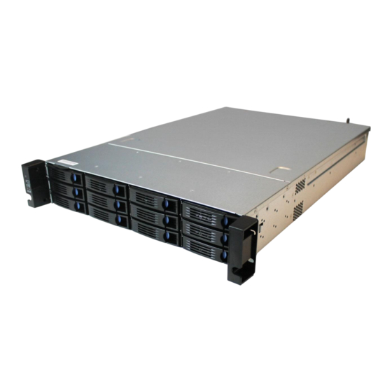
- Page 1 OPEN GREEN STABLE Stable and Reliable Solution Barebone 2U12L6SC User Manual...
- Page 2 Version 1.0 Published August 2013 Copyright©2013 ASRockRack Inc. All rights reserved. Copyright Notice: No part of this documentation may be reproduced, transcribed, transmitted, or translated in any language, in any form or by any means, except duplication of documentation by the purchaser for backup purpose, without written consent of ASRockRack Inc.
- Page 3 Important Safety Instructions Pay close attention to the following safety instructions before performing any of the operation. Basic safety precautions should be followed to protect yourself from harm and the product from damage: • Operation of the product should be carried out by suitably trained, qualified, and certified personnel only to avoid risk of injury from electrical shock or energy hazard.
- Page 4 Contact Information If you need to contact ASRockRack or want to know more about ASRockRack, you’re welcome to visit ASRockRack’s website at www.ASRockRack.com; or you may contact your dealer for further information. ASRockRack Incorporation 6F., No.37, Sec. 2, Jhongyang S. Rd., Beitou District, Taipei City 112, Taiwan (R.O.C.)
-
Page 5: Table Of Contents
Contents Chapter 1 Introduction Package Contents Chapter 2 Chassis Overview System Components System Front View System Rear View Chapter 3 Hardware Installation and Maintenance Chassis Cover Hard Drives System Fan Power Supply Backplanes Add-on Card Chassis Cables Chapter 4 Backplane Specifications Appendix A Rails Installation... -
Page 6: Chapter 1 Introduction
2U12L6SC Chapter 1 Introduction Thank you for purchasing 2U12L6SC, a reliable barebone system produced under ASRockRack’s consistently stringent quality control. It delivers excellent performance with robust design conforming to ASRockRack’s commitment to quality and endurance. Because the hardware specifications might be updated, the content of this documentation will be subject to change without notice. -
Page 7: Chapter 2 Chassis Overview
Chapter 2 Chassis Overview This chapter provides diagrams showing the location of important components of the server chassis. 2.1 System Components Cover Power Supply Units Air Baffle Max. PWM Fan (4 pcs) Front Controls and Indicators 12 x 3.5” Hot-Swap HD D Carriers... -
Page 8: System Front View
2U12L6SC 2.2 System Front View Front Control Panel Description System reset button Power LED Power Switch LAN1, LAN2 Activity LED 12 x 3.5" Hot-Swap HDD Carriers... - Page 9 Status LED Definitions Power LED Status Description Blue System is turned on Power off LAN1, LAN2 LED Status Description Green LAN linked LAN not linked...
-
Page 10: System Rear View
2U12L6SC 2.3 System Rear View Description Power supply unit 6 x 2.5" Hot-Swap HDD Carriers 3 x Low Profile PCI Express slots I/O shield (depends on the specification of the motherboard) -
Page 11: Chapter 3 Hardware Installation And Maintenance
Chapter 3 Hardware Installation and Maintenance This chapter helps you assemble the chassis and install components. 3.1 Chassis Cover Removing the Chassis Cover 1. Before removing the top cover, power off the server and unplug the power cord. 2. The system must be operated with the chassis top cover installed to ensure proper cooling. 1. - Page 12 2U12L6SC Installing the Chassis Cover 1. Slide the chassis cover toward the front of the chassis. Then latch the cover securely to the chassis. 2. Secure the chassis cover with the screws.
-
Page 13: Hard Drives
3.2 Hard Drives The 2U12L6SC chassis supports hot-swappable hard drives. Removing Hard Drive Trays from the Chassis 1. Press the locking lever latch on the drive tray to unlock the retention lever. 2. Rotate the lever out and away from the module bay and pull the hard drive out of the... - Page 14 2U12L6SC Installing a Hard Drive to the Hard Drive Tray 1. Place the HDD into the tray with the printed circuit board side facing down. Carefully align the mounting holes in the hard drive and the tray. 2. Secure the hard drive using the four screws.
-
Page 15: System Fan
3.3 System Fan Before replacing the system fan, power off the server and unplug the power cord. Replacing the System Fan Hold the clip and put the fan module into fan bar. Push all the way until it clicks into place. -
Page 16: Power Supply
2U12L6SC 3.4 Power Supply Before replacing the power supply, power off the server, unplug the power cord, and disconnect all wiring from the power supply. Replacing the Power Supply (Redundant) 1. Slide the PSU into the power supply module bay until it clicks into place. -
Page 17: Backplanes
3.5 Backplanes Each barebone system supports one 3.5-inch HDD backplane and two 2.5-inch HDD/SDD backplanes. The Hot-Swap SAS/SATA backplanes serve as the interface between the motherboard and the HDDs/SDDs. Before removing and installing backplanes, power off the server and unplug the power cord. For the specification of backplanes, please refer to the Chapter 4. - Page 18 2U12L6SC Installing the Backplane 1. Hold the backplane only by the edges. 2. Position the backplane in the server system. Align mounting holes of backplane to the standoff on the chassis. 3. Secure the backplane with the four screw.
- Page 19 The following diagram shows the location of blackplanes on the server chassis. BP_2x20_S3x4 BP_S2x2_25 BP_S2x1_25...
-
Page 20: Add-On Card
2U12L6SC 3.6 Add-on Card Before installing the add-on card, power off the server and unplug the power cord. Installing the Add-on Card in the Chassis 1. Remove the screw securing the cover in place for each low profile add-on slot you want to use. -
Page 21: Chassis Cables
3.7 Chassis Cables This section lists supported cables for your chassis system. 1. Single port SATA Cable (Quantity: 2) 2. SGPIO Cable (Quantity: 1) 3. MiniSAS-1 Cable (670mm) (Quantity: 1) Port 0-3 4. MiniSAS-2 Cable (670mm) (Quantity: 1) Port 4-7 5. - Page 22 2U12L6SC 6. MNG Cable (520mm+100mm)_SMB (Quantity: 1) 7. MNG Cable (960mm)_SMB (Quantity: 1)
-
Page 23: Chapter 4 Backplane Specifications
Chapter 4 Backplane Specifications 3.5-inch Hard Drive Backplane ( to connect 12 HDDs) BP_2x20_S3x4 Front View CON1 CON2 CON3 CON4 CON5 CON6 CON7 CON8 CON9 CON10 CON11 CON12 12 x SAS/SATA Hot-swap Connectors Rear View PWR2 SMB_1 MINI_SAS1 PWR4 UART_SEL 1 SMB_2 SMB_3 MINI_SAS2... - Page 24 2U12L6SC Jumper Setup The illustration shows how jumpers are setup. When the jumper cap is placed on the pins, the jumper is “Short”. If no jumper cap is placed on the pins, the jumper is “Open”. The illustration shows a 3-pin jumper whose pin1 and pin2 are “Short”...
- Page 25 #5, 6, 7 SMB Connector The SMB (SubMiniature (SMB_1) version B) connector (SMB_2) provides a communication (SMB_3) interface between the backplane and the +3VSB motherboard. Present# #8 Debug Connector The Debug Connector is used (DEBUG1) for the firmware upgrade and factory reset.
- Page 26 2U12L6SC 2.5-inch Hard Drive Backplane ( to connect 4 HDDs) BP_S2x2_25 ( to connect 4 HDDs) Front View CON2 CON4 CON1 CON3 2 x SAS/SATA Hot-swap Connectors Rear View DEBUG 1 PWR1 SMB_1 BP_S2x2_25 Description Intelligent Platform Management Bus Header (SMB_1)
- Page 27 Pin Definitions #1 Intelligent Platform This 4-pin connector IPMB_SMBDATA Management Bus Header provides a communication (SMB_1) interface between the backplane and the IPMB_SMBCLK motherboard. It allows +3VSB basic monitoring of I2C_1_PRESENT_N voltages, fans, and temperature. #2 Mini-SAS Connector This connector is used (MINI_SAS1) to connect RAID card or the mini-SAS port on the...
- Page 28 2U12L6SC BP_S2x1_25 ( to connect 2 SSDs) Front View 2x SAS/SATA Hot-swap Connectors CON2 CON1 Rear View SGPIO1 SAS2 DEBUG 1 SAS1 PWR1 SMB_1 Description Power Connector (PWR1) SGPIO Connector (SGPIO1 ) SAS Connector (SAS2) Debug Connector (DEBUG1) SAS Connector (SAS1)
- Page 29 Pin Definitions #1 Power Connector The 4-pin connectors +12V (PWR1) provide power to the back- GND2 plane. GND1 #2 Serial General This header supports Serial SCLOCK SLOAD Purpose Link interface for onboard Input/Output Header SATA connections. (SGPIO_1) SDATAOUT0 SDATAIN0 #3, 5 SAS Connectors These two SAS connectors (SAS1, SAS2) support SAS/SATA data...
- Page 30 2U12L6SC #6 Intelligent Platform This 4-pin connector IPMB_SMBDATA Management Bus provides a communication IPMB_SMBCLK Header interface between the +3VSB I2C_1_PRESENT_N (SMB_1) backplane and the motherboard. It allows basic monitoring of voltages, fans, and temperature.
- Page 31 Drive Present, No Activity Drive Present, Activity Blinking Locate (Identify) Blinking Drive Fail Rebuild Blinking Blinking Front LED Indicators SGPIO-SDATAOUT bit ASRock Rack BPB LED Behavior (SAS/SATA HDD) Fail Locate Description Activity(Green) (Red) (Blue) Empty Idle Access Drive Not Present...
-
Page 32: Appendix A Rails Installation
2U12L6SC Appendix A Rails Installation The rails installation instructions in this manual are example only, your actual rail assembly procedure may differ slightly . Installing the Rails 1. Pull out the inner rail from rail assembly by pulling the front activating release latch forward. - Page 33 3. Each slide is pre-attached with front and rear adjustable EIA brackets. Loosen the nuts on the both brackets, and decide the proper setback distance to the opening, then tighten the nuts on the front brackets. 4. Extend the rear brackets to where it reaches the rear rack. Do not fully tighten rear bracket mounting screws until final adjustment is made.
- Page 34 2U12L6SC Optional Slide Rail Kit The optional slide rail kit is available for you to order, as listed below. Optional Accessory – Slide Rail Kit Vendor Model name Chenbro 84H341300-002...
Need help?
Do you have a question about the 2U12L6SC and is the answer not in the manual?
Questions and answers