
Related Manuals for ASROCK Rack 4U60L Series


Summary of Contents for ASROCK Rack 4U60L Series
- Page 1 4U60L Series User Manual Version 1.0 Published June 2015 Copyright©2015 ASRock Rack INC. All rights reserved.
- Page 2 Version 1.0 Published June 2015 Copyright©2015 All rights reserved. Copyright Notice: No part of this documentation may be reproduced, transcribed, transmitted, or translated in any language, in any form or by any means, except duplication of documentation by the purchaser for backup purpose, without written consent of us. Products and corporate names appearing in this documentation may or may not be registered trademarks or copyrights of their respective companies, and are used only for identiication or explanation and to the owners’...
- Page 3 Important Safety Instructions Pay close attention to the following safety instructions before performing any of the operation. Basic safety precautions should be followed to protect yourself from harm and the product from damage: • Operation of the product should be carried out by suitably trained, qualiied, and certiied personnel only to avoid risk of injury from electrical shock or energy hazard.
-
Page 4: Table Of Contents
Contents Chapter 1 Introduction System Package Contents Speciications Chapter 2 Server System Overview System Components Board Arrangement System Front Panel System Rear Panel Front Control Panel Buttons and LEDs Drive Tray LEDs PSU LED Fan Failed LED (Middle System Fan) Backplane LEDs Chapter 3 Hardware Installation and Maintenance Server Top Cover... - Page 5 Appendix A Installing the CPU (Socket: LGA2011) Installing the CPU Fan and Heatsink Installation of Memory Modules (DIMM) Appendix B Installing the Server in a Rack...
-
Page 6: Chapter 1 Introduction
4U60L Series Chapter 1 Introduction hank you for purchasing ASRock Rack 4U60L Series, a reliable barebone system produced under ASRockRack’s consistently stringent quality control. It delivers excellent performance with robust design conforming to ASRockRack’s commitment to quality and endurance. Because the hardware speciications might be updated, the content of this documentation will be subject to change without notice. -
Page 7: System Package Contents
Zoning, and Single Node (JBOD).* Please refer to the table below for the required components for each mode. Quantity for Diferent Mode Item Zoning Single Node 4U60L Series Barebone (4U form factor) Motherboards (MB)** Expander Board (EXPB) Expander Board (EXPBZ) HA Daughter Board (DBH)*** Zoning Daughter Board (DBZ)***... -
Page 8: Speciications
4U60L Series 1.2 Speciications 4U60L Series System Physical Status Form Factor 4U Rackmount Dimension 35.4"* x 16.9" x 6.94" (900* x 430 x 176.5 mm) (D x W x H) *Chassis ears excluded Support MB Size Half Width, 13'' x 5.96'' (330 x 151 mm) -
Page 9: Chapter 2 Server System Overview
Chapter 2 Server System Overview his chapter provides diagrams showing the location of important components of the server system. 4U60L Series:... -
Page 10: System Components
4U60L Series 2.1 System Components... - Page 11 Item Front System Fan (Fan5) Front System Fan (Fan4) Front System Fan (Fan3) Front System Fan (Fan2) Front System Fan (Fan1) 60 x 3.5'' or 2.5" HDD Bays (HDD0~HDD59) Middle System Fan (Fan9) Middle System Fan (Fan8) Middle System Fan (Fan7) Middle System Fan (Fan6) Node2 Node1...
-
Page 12: Board Arrangement
4U60L Series 2.2 Board Arrangement Item 3.5"/2.5" HDD Backplane Board 5 (BPB5) 3.5"/2.5" HDD Backplane Board 4 (BPB4) 3.5"/2.5" HDD Backplane Board 3 (BPB3) 3.5"/2.5" HDD Backplane Board 2 (BPB2) 3.5"/2.5" HDD Backplane Board 1 (BPB1) Daughter Board (DB)* Middle Plane Board (MPB) -
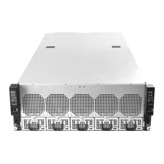
Page 13: System Front Panel
2.3 System Front Panel Item Control Panel Buttons and LEDs (Let) (for Node 1) 2 x USB 2.0 Ports (Let) (for Node 1) 5 x HDD Backplane Trays 2 x USB 2.0 Ports (Right) (for Node 2) Control Panel Buttons and LEDs (Right) (for Node 2) -
Page 14: System Rear Panel
4U60L Series 2.4 System Rear Panel WARNING! Do NOT open the trays if the server is not powered down or while it is still running. Item Add-on Card Slot (MB2) *Supports Low proile and FHHL (Full High Half Length) add-on cards **When the PCIE1 slot on the E3C224D4HM-8R motherboard is populated, the LSI SAS connec- tors will be disabled. -
Page 15: Front Control Panel Buttons And Leds
2.5 Front Control Panel Buttons and LEDs Front Control Panel Boards Item MB1 Power Button and LED MB1 ID Button and LED* MB1 LAN1, LAN2, LAN3, LAN4 Activity LEDs* MB1 HDD Activity LED MB1 System Event LED* MB1 NMI (Nonmaskable Interrupt) Button* MB1 System Reset Button MB2 Power Button and LED MB2 ID Button and LED*... - Page 16 4U60L Series ID Button Press the ID button to toggle the front panel ID LED and the baseboard ID LED on and of. You are able to locate the server you’re working on from behind a rack of servers. NMI (Nonmaskable Interrupt) Button Press the NMI button with a paper clip or pin to generate a nonmaskable interrupt and to put the server in a halt state for examination.
-
Page 17: Drive Tray Leds
2.6 Drive Tray LEDs Description HDD Power LED HDD Activity LED Status LED Deinitions HDD Power LED Status Description Blue HDD powered-on No power to HDD HDD Activity LED Status Description Solid Green HDD active Blinking Green HDD accessing or reading HDD failed HDD powered-of... -
Page 18: Psu Led
4U60L Series 2.7 PSU LED PSU LED PSU Status LED Status Description Green blinking at 1Hz Standby/Cold redundant state or PDB fault/protection Green Normal work Amber continuously Module fault/protection in operating mode Amber blinking at 1Hz Warning Green blinking at 0.5Hz Power cord unplugged/AC loss 2.8 Fan Failed LED... -
Page 19: Backplane Leds
2.9 Backplane LEDs BPB1 BPB2 BPB3 BPB4 BPB5 Status Description BPB1 HDD Activity Blinking Green HDD0~HDD11 active and accessing* BPB1 HDD Error Solid Red BPB1 HDD error BPB1 PWR Error Solid Amber BPB1 power error BPB1 FAN Error Solid Amber BPB1 Fan1 error BPB2 HDD Activity Blinking Green HDD12~HDD23 active and accessing*... -
Page 20: Chapter 3 Hardware Installation And Maintenance
4U60L Series Chapter 3 Hardware Installation and Maintenance his chapter helps you assemble the chassis and install components. Before You Begin Before you work with the server, pay close attention to the “Important Safety Instructions” at the beginning of this manual. -
Page 21: Server Top Cover
3.1 Server Top Cover Removing the Server Top Cover 1. Before removing the top covers, power of the server and unplug the power cord. 2. he system must be operated with all the chassis top covers installed to ensure proper cooling. 1. - Page 22 4U60L Series Installing the Server Top Cover 1. Lower the top cover on the chassis, making sure the side latches align with the cutouts. 2. Slide the top front cover toward the REAR of the chassis. 3. Secure the top cover with the eight screws.
-
Page 23: Hard Drive
3.2 Hard Drive 3.2.1 Installing a Hard Disk Drive into 2.5" Hard Drive Tray he 4U60L series chassis supports hot-swappable 2.5" hard drives. Four 2.5" hard drive trays are located on the rear of the chassis. Removing 2.5” Hard Drive Trays from the Chassis 1. - Page 24 4U60L Series Installing a 2.5” Hard Drive to the Hard Drive Tray 1. Place a 2.5" HDD into the tray with the printed circuit board side facing down. Carefully align the mounting holes in the hard drive and the tray.
-
Page 25: Installing A 3.5" Or 2.5" Hard Disk Drive Into The Hard Drive Carrier
3.2.2 Installing a 3.5” or 2.5” Hard Disk Drive into the Hard Drive Carrier Removing a Hard Drive Carrier from the Chassis 1. Push back the black release latch. 2. While holding the latch back in the unlocked position, pull the hard drive carrier up and out towards you. - Page 26 4U60L Series Installing a 3.5” Hard Drive to the Hard Drive Carrier 1. Remove the screws to disengage the hard drive mounting bracket from the carrier. 2. Place the 3.5" HDD into the bracket with the label facing up and the connector end toward the opening of the bracket.
- Page 27 Installing a 2.5” Hard Drive to the Hard Drive Carrier 1. Place the 2.5" HDD into the carrier with the label facing up and the connector end toward the rear of the carrier. Carefully align the mounting holes in the hard drive and the carrier. 2.
- Page 28 4U60L Series Installing a Hard Drive Carrier into the Chassis 1. Gently slide the HDD carrier into the chassis evenly. 2. Push the carrier downwards until it is irmly seated and locks into place.
-
Page 29: Power Supply
3.3 Power Supply The 4U60L Series can accommodate four CRPS (Common Redundant Power Supplies) power supplies in the bay at the rear of the chassis. Each unit provides up to 800 Watts of power. hree power supplies are required for operation, with the other power supply purely as a redundant, load-sharing backup. - Page 30 4U60L Series Removing the Power Supply Unit To remove a failed power supply, identify the failed power supply by checking the power supply LEDs on the PSU. 1. Hold onto the power supply handle while pressing the locking lever towards the power supply handle.
-
Page 31: Add-On Card
3.4 Add-on Card Before installing the add-on card, power of the server and unplug the power cord. Installing the Add-on Card in the Chassis 1. Remove the screw securing the cover in place for each low proile add-on slot you want to use. - Page 32 4U60L Series Removing the Blanking Plate for a LAN Mezzanine Card You can use an optional Ethernet mezzanine card for additional LAN ports. Please be aware that the mezzanine card must be used in conjunction with a matching I/O module.\ Remove the two screws that secure the blanking plate on the chassis.
-
Page 33: System Fan
3.5 System Fan he 4U60L series chassis supports hot-swappable system fans. Replacing the System Fan Before replaceing the system fan, remove the top cover from the chassis. (See p. 16 for more details.) Front Fan Module 1. Push back the release latch at the top of the front fan. - Page 34 4U60L Series Middle Fan Module 1. Press and hold the clip on the middle fan 2. Lit the system fan away from the chassis.
-
Page 35: Motherboard
3.6 Motherboard Attention! DO NOT open the motherboard tray if the server is not powered down or while it is still running. Replacing the Motherboard You must remove all connected cables from the motherboard to avoid damaging the motherboard and its components when you remove it later. 1. - Page 36 4U60L Series Motherboard Conigurations Board HA Mode Zoning Mode Single Node Mode EXPB1 EXPB EXPB EXPB EXPB2 EXPB EXPBZ idle idle HA(High Availability) Mode: Node1 and Node2 support 60 SAS HDDs. When one of the nodes operates normally, the other node idles. If an unexpected error, crash or shutdown occurs on the operating node, the idle node then takes over the job.
-
Page 37: Daughter Board
3.7 Daughter Board Replacing the Daughter Board Depending on the HA mode, Zoning mode or Single Node mode you require for your system, install the compatible daughter board for proper functionality. HA Mode Zoning Mode Single Node Mode CON1 CON3 CON1 CON3 CON1... - Page 38 4U60L Series 3. Gently and vertically lit up and remove the daughter board from the Expander Board (EXPB). 4. Correctly orientate the daughter board you need. When facing the rear of the chassis, the CON1 on the daughter board you are about to install should be at the right-bottom corner.
- Page 39 5. Align the connectors on the daughter board with the Expander Board card connectors. Vertically install the daughter board to the the Expander Board card with a little pressure. 6. hen install the daughter board bracket back to the chassis with screws. 7.
-
Page 40: Appendix A
4U60L Series Appendix A Installing the CPU 1. Before you insert the 1150-Pin CPU into the socket, please check if the PnP cap is on the socket, if the CPU surface is unclean, or if there are any bent pins in the socket. Do not force to insert the CPU into the socket if above situation is found. - Page 41 Please save and replace the cover if the processor is removed. he cover must be placed if you wish to return the motherboard for ater service.
-
Page 42: Installing The Cpu Fan And Heatsink
4U60L Series Installing the CPU Fan and Heatsink Before you installed the heatsink, you need to spray thermal interface material between the CPU and the heatsink to improve heat dissipation. -
Page 43: Installation Of Memory Modules (Dimm)
Installation of Memory Modules (DIMM) he DIMM only its in one correct orientation. It will cause permanent damage to the motherboard and the DIMM if you force the DIMM into the slot at incorrect orientation. For more information about DIMM installation, please refer to the User Manual that comes with the serverboard you use. -
Page 44: Appendix B
4U60L Series Appendix B Installing the Server in a Rack his section describes how to rackmount the server with slide rail assemblies. 1. he rails installation instructions in this manual are example only, your actual rail assembly procedure may difer slightly . - Page 45 To slide a chassis rail back into the slide rail assembly, slide the blue release tab toward the rear, and simultaneously slide the chassis rail into the slide rail assembly until it is locked and cannot be pushed further. Attaching the Chassis Rails to the Server Position a chassis rail along one side of the chassis, and align the keyhole openings on the chassis rail with the keyhole openings on the side of the chassis.
- Page 46 4U60L Series Attaching the Slide Rail Assemblies to the Rack Determine where to attach the slide rails. Make sure you have enough free space above the slide rail bracket for the chassis. 4U Server 1 1 U Free Space Free Space...
- Page 47 Extend the pre-attached front and rear adjustable brackets on the slide. Rear Bracket Front Bracket Adjust the brackets to accommodate the depth of the rack. 1 1 U...
- Page 48 4U60L Series Align the holes on the brackets with the mounting holes you selected on the rack. Add a washer between the screw and the cabinet rail. Tighten the screw to secure the slide rails to the rack. 1 1 U...
- Page 49 Sliding the Server into the Rack Ensure that the slide rails are properly and securely attached to the rack. Fully extend the slide rails from the rack by pulling the inner rails out until they are locked and cannot be pulled out further.
- Page 50 4U60L Series Slide the release tabs on both sides and slide the server slowly and evenly all the way into the cabinet to ensure that the slide assemblies are working correctly. he server is heavy. For safe liting, two or more persons are required to install the server into the rack.
- Page 51 Tighten the two thumb screws on the front of the server to secure the server to the rack. To remove the server from the rack, reverse these instructions. When connecting cables to the server, make sure there is enough cable slack so you can slide the server in and out of the rack without accidentally unplugging a cable.
Need help?
Do you have a question about the 4U60L Series and is the answer not in the manual?
Questions and answers