Table of Contents
Advertisement
Quick Links
Advertisement
Table of Contents

Related Manuals for ASROCK Rack 1U12E-EGS/2L2Q


Summary of Contents for ASROCK Rack 1U12E-EGS/2L2Q
-
Page 2: Copyright Notice
In no event shall ASRock Rack, its directors, officers, employees, or agents be liable for any indirect, special, incidental, or consequential damages (including damages for loss of profits, loss of business, loss of data, interruption of business and the like), even if ASRock Rack has been advised of the possibility of such damages arising from any defect or error in the documentation or product. - Page 3 “Perchlorate Material-special handling may apply, see www.dtsc.ca.gov/hazardouswaste/ perchlorate” ASRock Rack’s Website: www.ASRockRack.com Setting up the Server in a Restricted Access Location/Restricted Access Area • Access can only be gained by service persons or by users who have been instructed about the reasons for the restrictions applied to the location and about any precautions that shall be taken.
-
Page 4: Replaceable Batteries
Replaceable Batteries CAUTION RISK OF EXPLOSION IF BATTERY IS REPLACED BY AN INCORRECT TYPE. DISPOSE OF USED BATTERIES ACCORDING TO THE INSTRUCTIONS Warning When removal of the chassis lid required for servicing: - Turn off power and unplug any power cords/cables, and - Reinstall the chassis lid before restoring power. -
Page 5: Table Of Contents
Contents Chapter 1 Introduction Shipping Box Contents Specifications Chapter 2 Server System Overview System Components Internal Features System Front Panel System Rear Panel Front Control Panel Buttons and LEDs Drive Tray LEDs Chapter 3 Hardware Installation and Maintenance Server Top Cover Hard Drive Install OCP System Fan... -
Page 7: Chapter 1 Introduction
1U12E-EGS/2L2Q Chapter 1 Introduction Thank you for purchasing 1U12E-EGS/2L2Q, a reliable barebone system produced under ASRock Rack’s consistently stringent quality control. It delivers excellent performance with robust design conforming to ASRock Rack’s commitment to quality and endurance. This guide provides the instructions of insertion and extraction of chassis components, such as chassis covers, system fans, power supplies, hard disk drive trays, and other main components this system supports. -
Page 8: Shipping Box Contents
1.1 Shipping Box Contents Item Quantity 1U12E-EGS/2L2Q Barebone (1U form factor) System Boards (MB)* Power Supply Units* System Fans* HDD Backplane (BPB)* Power Distribution Board (PDB)* Riser Cards* Accessory Box 1U Cooler Slide Rail Quick Installation Guide * The components are pre-installed. -
Page 9: Specifications
1U12E-EGS/2L2Q 1.2 Specifications 1U12E-EGS/2L2Q System Physical Status Form Factor 1U Rackmount Dimension 676.5 x 438 x 43.4 mm (26.6'' x 17.2'' x 1.7'') Support MB SPC741D16QM3-2L2Q Front Panel • Power • Reset Buttons • ID button • NMI button • Power •... -
Page 10: Chapter 2 Server System Overview
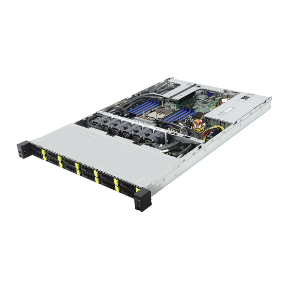
Chapter 2 Server System Overview This chapter provides diagrams showing the location of important components of the server system. 2.1 System Components Riser Card (default only support X8) (RB2) 1 x Power Supply Units Riser Card (RB1) 6 x System Fans Server Board Front Controls and Indicators 12 x 2.5”... -
Page 11: Internal Features
1U12E-EGS/2L2Q 2.2 Internal Features... - Page 12 Description Riser Card (default only support X8) Serverboard 2 x Power Supply Units (PSU) System Fan 1 System Fan 2 System Fan 3 System Fan 4 System Fan 5 System Fan 6 2.5" HDD Backplane Board (BPB) 1 x Type-A (USB3.2 Gen1) 12 x 2.5"...
-
Page 13: System Front Panel
1U12E-EGS/2L2Q 2.3 System Front Panel HDD2 HDD4 HDD6 HDD8 HDD10 HDD12 HDD9 HDD11 HDD1 HDD3 HDD5 HDD7 Description 1 x Type-A (USB3.2 Gen1) 12 x 2.5" Hot-Swap HDD Trays (2.5" NVMe / SATA SSD / SAS HDD) Control Panel (depends on the specification of the server board) 2.4 System Rear Panel... -
Page 14: Front Control Panel Buttons And Leds
2.5 Front Control Panel Buttons and LEDs Front Control Panel LEFT SIDE RIGHT SIDE ID ID Description USB 3.2 Gen1 Port System Reset Button NMI (Nonmaskable Interrupt) Button Power Button and LED ID Button and LED HDD Status LED System Status LED LAN1 and Activity LED LAN2 and Activity LED *Please be noted that the functions are supported depending on the type of the server board. -
Page 15: Status Led Definitions
1U12E-EGS/2L2Q Status LED Definitions Power LED Status Description Green Power on Power off LAN1, LAN2 LED Status Description Green Link between system and network or no access Blinking Green Network access... -
Page 16: Drive Tray Leds
LEDs Hard Drive Tray Description Hard Drive Tray Status LED Hard Drive Tray Activity LED LED Definitions Description Activity (No.2) Status (No.1) Drive Not Present Drive Present(no active) Solid Green Solid Blue Drive Present(active) Green Blinking at 4Hz Solid Blue Locate Solid Green Blue Blinking at 4Hz... -
Page 17: Chapter 3 Hardware Installation And Maintenance
1U12E-EGS/2L2Q Chapter 3 Hardware Installation and Maintenance This chapter helps you assemble the chassis and install components. Before You Begin Before you work with the server, pay close attention to the “Important Safety Instructions” at the beginning of this manual. -
Page 18: Server Top Cover
3.1 Server Top Cover Removing the Server Top Cover 1. Before removing the top cover, power off the server and unplug the power cord. 2. The system must be operated with the chassis top cover installed to ensure proper cooling. 1. - Page 19 1U12E-EGS/2L2Q...
- Page 20 Installing the Server Top Cover 1. For installation, align both side latches with the cutouts. Lower and slide the top front cover toward the FRONT and secure it with screws to the chassis. 2. Lower and slide the top rear cover toward the FRONT and secure it with a rear thumbscrew and a top screw to the chassis.
- Page 21 1U12E-EGS/2L2Q...
-
Page 22: Hard Drive
3.2 Hard Drive Removing Hard Drive Trays from the Chassis 1. Press the locking lever latch to open the lever. 2. Pull the driver carrier out. - Page 23 1U12E-EGS/2L2Q Install 2.5” Hard Drive 1. Place the HDD into the carrier with printed circuit board side facing down. 2. Use the screws to secure the HDD. Slide the driver carrier into the HDD bay. Push in the locking lever to lock the HDD carrier into place.
-
Page 24: Install Ocp
3.3 Install OCP Remove Slot Cover Release the thumbscrew that secures the slot cover to the chassis and remove the slot cover. Install OCP Card Install an OCP card into the slot. Make sure the card is well seated and hand-tighten the thumbscrew on the face plate. -
Page 25: System Fan
1U12E-EGS/2L2Q 3.4 System Fan Replace FAN Press and hold the fan clip on to replace the fan. -
Page 26: Replace Psu
3.5 Replace PSU Press the locking lever and hold on the handle to pull the Old PSU out. Slide the New PSU into the power supply... -
Page 27: Add-In Card
1U12E-EGS/2L2Q 3.6 Add-in Card Replace Add-in Card 1. Release the thumbscrew to lift up the riser-card bracket. 2. Remove the screw to slide the blanking plate out. -
Page 28: Installing Add-In Card
Installing Add-in Card 1. Install riser card to the bracket and secure it with screws. 2. Install the add-on card to the bracket assembly and secure it with a screw. - Page 29 1U12E-EGS/2L2Q Install the riser-card assembly to the chassis with the thumbscrew. The illustration is for references only. The actual location may be slightly differnet by models.
-
Page 30: Installing The Cpu
Appendix A Installing the CPU (LGA 4677 Socket) Unplug all power cables before installing the CPU. Socket Dust Cover CPU Carrier... - Page 31 1U12E-EGS/2L2Q...
- Page 33 1U12E-EGS/2L2Q CPU Carrier...
- Page 34 Heatsink CPU Carrier Socket...
- Page 35 1U12E-EGS/2L2Q...
-
Page 36: Installation Of Memory Modules (Dimm)
Appendix B Installation of Memory Modules (DIMM) The DIMM only fits in one correct orientation. It will cause permanent damage to the motherboard and the DIMM if you force the DIMM into the slot at incorrect orientation. For more information about DIMM installation, please refer to the User Manual that comes with the server board used. - Page 37 1U12E-EGS/2L2Q Type B (Two Clips)
- Page 38 Appendix C Block Diagram (SPC741D16QM3-2L2Q) FW SPI NCSI Serial...
-
Page 39: Contact Information
1U12E-EGS/2L2Q Contact Information Contact ASRock Rack or want to know more about ASRock Rack, you’re welcome to visit ASRock Rack’s website at http://www.asrockrack.com; or contact the dealer for further information. For technical questions, please submit a support request form at https://event.
Need help?
Do you have a question about the 1U12E-EGS/2L2Q and is the answer not in the manual?
Questions and answers