
Related Manuals for ASROCK Rack TR-KNL


Summary of Contents for ASROCK Rack TR-KNL
- Page 1 TR-KNL User Manual Version 1.0 Published June 2016 Copyright©2016 All rights reserved.
- Page 2 Version 1.0 Published June 2016 Copyright©2016 All rights reserved. Copyright Notice: No part of this documentation may be reproduced, transcribed, transmitted, or translated in any language, in any form or by any means, except duplication of documentation by the purchaser for backup purpose, without written consent of us. Products and corporate names appearing in this documentation may or may not be registered trademarks or copyrights of their respective companies, and are used only for identification or explanation and to the owners’...
- Page 3 Setting up the Server in a Restricted Access Location • Access can only be gained by service persons or by users who have been instructed about the reasons for the restrictions applied to the location and about any precautions that shall be taken. • Access is through the use of a tool or lock and key, or other means of security, and is controlled by the authority responsible for the location.
-
Page 4: Table Of Contents
Contents Chapter 1 Introduction Shipping Box Contents Specifications Chapter 2 Server System Overview Front View Rear View Front Control LED Indicators Inside View Chapter 3 Hardware Installation and Maintenance Hard Drive System Fan Server Board Add-on Card Optical Drive (ODD) Appendix A Installing the CPU (Socket: FC-LGA/MCP 3647) Installing the CPU Fan and Heatsink... -
Page 5: Chapter 1 Introduction
TR-KNL Chapter 1 Introduction Thank you for purchasing TR-KNL, a reliable system produced under our consistently stringent quality control. It delivers excellent performance with robust design conforming to our commitment to quality and endurance. Because the hardware specifications might be updated, the content of this documentation will be subject to change without notice. -
Page 6: Specifications
120 x 25 mm Fan x3 Power Supply Type Single Output Watts 600 W 1. Please contact ASRock Rack sales for target system configuration. 2. Please refer to the user manual of the motherboard you use for detailed information about motherboard components and features. -
Page 7: Chapter 2 Server System Overview
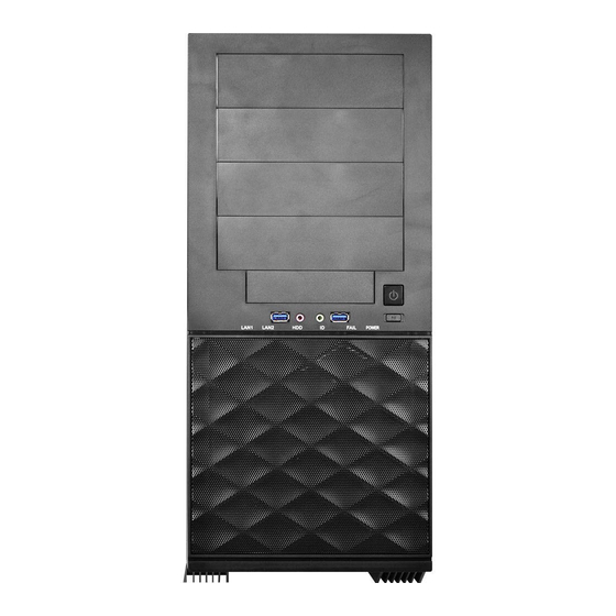
TR-KNL Chapter 2 Server System Overview This chapter provides diagrams showing the location of important components of the server system. 2.1 Front View Item Microphone port (Pink)* USB 3.0 port (USB1) Headphone port (Lime)* USB 3.0 port (USB2) Power button... - Page 8 System Reset Button When the system is completely unresponsive, press the system reset button to reboot the server without shutting it off and initialize the system. Power Button Press the power switch button to toggle the system power on and off modes. To remove all power from the system completely, disconnect the power cord from the server.
-
Page 9: Rear View
AC input power connector Power supply unit I/O Shield (depends on the specifi cation of the server board) System fan 7 x Add-on card slots* *Th e TR-KNL system only supports Slot 2 and Slot 7 for add-on card installation. -
Page 10: Front Control Led Indicators
2.3 Front Control LED Indicators Description LAN1 Activity LED* LAN2 Activity LED* HDD Activity LED UID LED* System Fail LED Power LED *Please be noted that the functions are supported depending on the type of the server board. UID LED Press the UID button on the rear panel to toggle the front panel UID LED on and off. - Page 11 TR-KNL Status LED Definitions LAN1, LAN2 LEDs Status Description No access Blinking Amber Network access UID LED Status Description Blue System identification is active. System identification is disabled. HDD Activity LED Status Description Blinking Green HDD access HDD idle System Fail LED...
-
Page 12: Inside View
Description 1 x Power Supply Unit (600W) Rear System Fan 7 x Add-on Card Slots* *The TR-KNL system only supports Slot 2 and Slot 7 for add-on card installation. Server Board Front System Fan 1 Front System Fan 2 Media Bays* Drive Bays* *Please be noted that the functions are supported depending on the type of the server board. -
Page 13: Chapter 3 Hardware Installation And Maintenance
TR-KNL Chapter 3 Hardware Installation and Maintenance This chapter helps you assemble the chassis and install components. Before You Begin Before you work with the server, pay close attention to the “Important Safety Instructions” at the beginning of this manual. -
Page 14: Hard Drive
3.1 Hard Drive Installing a Hard Disk Drive into Hard Drive Tray Five hard drive trays are located inside the case. Each of the trays can support either a 2.5" or 3.5" drive. Removing Hard Drive Trays from the Chassis 1. - Page 15 TR-KNL Installing a 3.5” Hard Drive to the Drive Tray 1. Fit the right edge of the drive into the tray, pressing the drive firmly backward against the stop tab near the right side of the tray. 2. Lower the left side of the drive into the tray until the drive snaps into place.
- Page 16 Remove the right side panel of the case to attach the SATA and power cables to the hard drive and route the cables. Removing a 3.5” Hard Drive from the Drive Trays Remove the drive tray from the disk drive that you pulled out of the system if you are replacing a disk drive.
- Page 17 TR-KNL Installing and Removing a 2.5” Hard Drive 1. Remove the stop tab at the upper right corner of the tray. 2. Place a 2.5" HDD into the tray with the printed circuit board side facing down. Carefully align the mounting holes in the hard drive and the tray.
-
Page 18: System Fan
3.2 System Fan Replacing the Front Fan Removing the failed fan 1. Unplug the fan connecter. Release the screw that secures the fan assembly to the chassis. 2. Pull the fan assembly away from the chassis. 3. Slightly bend the fan holder to release the tabs. 4. - Page 19 TR-KNL Installing a new fan 1. Attach the fan to the fan holder. 2. Align the mounting holes on chassis with the tabs on the fan assembly. 3. Make sure the tabs are firmly in place and gently hold the fan assembly close to the chassis.
- Page 20 Replacing the Rear System Fan 1. Unplug the fan connecter. Release the four screws that secure the fan to the chassis. 2. Remove the failed fan. 3. Reverse the procedures to install the rear fan.
-
Page 21: Server Board
TR-KNL 3.3 Server Board Installing and Removing the Server Board 1. Disconnect all cables attached to the server board. 2. Remove screws on the server board. 3. Lift the server board up from the chassis. 4. Hold the server board only by the edges and on a stable and antistatic surface. -
Page 22: Add-On Card
2. Slide the blanking plate out sideways. *The TR-KNL system only supports Slot 2 and Slot 7 for add-on card installation. 3. Align the plate of the add-on card with the openings in the back of the chassis. 4. Attach the add-on card to the chassis with the screw that was previously set aside. -
Page 23: Optical Drive (Odd)
TR-KNL 3.5 Optical Drive (ODD) Installing and Removing an Optical Drive to the Chassis 1. Release the three tabs on the side of the front bezel. 2. Swing the front panel outward, then remove the bezel. 3. Release the screws and remove the blank on the chassis. -
Page 24: Installing The Cpu (Socket: Fc-Lga/Mcp 3647)
Appendix A Installing the CPU (Socket: FC-LGA/MCP 3647) 1. Before you insert the CPU into the socket, please check if the PnP cap is on the socket, if the CPU surface is unclean, or if there are any bent pins in the socket. Do not force to insert the CPU into the socket if above situation is found. - Page 25 TR-KNL Pin1...
-
Page 26: Installing The Cpu Fan And Heatsink
Installing the CPU Fan and Heatsink 1. Before you installed the heatsink, you need to spray thermal interface material between the CPU and the heatsink to improve heat dissipation. 2. Illustration in this documentation are examples only. Heatsink or fan cooler type may differ. Tighten the two Middle Nuts to 3 IN.LB.
Need help?
Do you have a question about the TR-KNL and is the answer not in the manual?
Questions and answers