
Related Manuals for ASROCK Rack 1U10E-ROME/2T


Summary of Contents for ASROCK Rack 1U10E-ROME/2T
- Page 1 1U10E-ROME/2T User Manual Version 1.0 Published June 2020 Copyright©2020 ASRock Rack INC. All rights reserved.
- Page 2 In no event shall ASRock Rack, its directors, officers, employees, or agents be liable for any indirect, special, incidental, or consequential damages (including damages for loss of profits, loss of business, loss of data, interruption of business and the like), even if ASRock Rack has been advised of the possibility of such damages arising from any defect or error in the documentation or product.
- Page 3 Setting up the Server in a Restricted Access Location • Access can only be gained by service persons or by users who have been instructed about the reasons for the restrictions applied to the location and about any precautions that shall be taken. • Access is through the use of a tool or lock and key, or other means of security, and is controlled by the authority responsible for the location.
-
Page 4: Table Of Contents
Contents Chapter 1 Introduction Shipping Box Contents Specifications Chapter 2 Server System Overview System Components Internal Features System Front Panel System Rear Panel Front Control Panel Buttons and LEDs Drive Tray LEDs Chapter 3 Hardware Installation and Maintenance Server Top Cover Hard Drive System Fan Server Board... -
Page 5: Chapter 1 Introduction
In case any modifications of this documentation occur, the updated version will be available on ASRock Rack’s website without further notice. If you require technical support related to this product, please visit our website for specific information about the model you are using. -
Page 6: Shipping Box Contents
1.1 Shipping Box Contents Item Quantity 1U10E-ROME/2T Barebone (1U form factor) System Boards (MB)* Power Supply Units* System Fans* HDD Backplane (BPB)* Front Panel Board (FPB)* Fan Cable (L:300mm) SATA Cable Accessory Box 1U Cooler Riser Board Slide Rail * The components are pre-installed. -
Page 7: Specifications
1U10E-ROME/2T 1.2 Specifications 1U10E-ROME/2T System Physical Status Form Factor 1U Rackmount Dimension 625.0 mm x 430.0 mm x 44.5 mm (L/W/H) Support MB Size ATX MB Model ROMED8QM-2T Front Panel Buttons • Power button • System reset button • NMI button LEDs •... -
Page 8: Chapter 2 Server System Overview
Chapter 2 Server System Overview This chapter provides diagrams showing the location of important components of the server system. 2.1 System Components 2 x Power Supply Units Riser Board 6 x System Fans Server Board 10 x 2.5” Hot-Swap HDD Trays Front Controls and Indicators... -
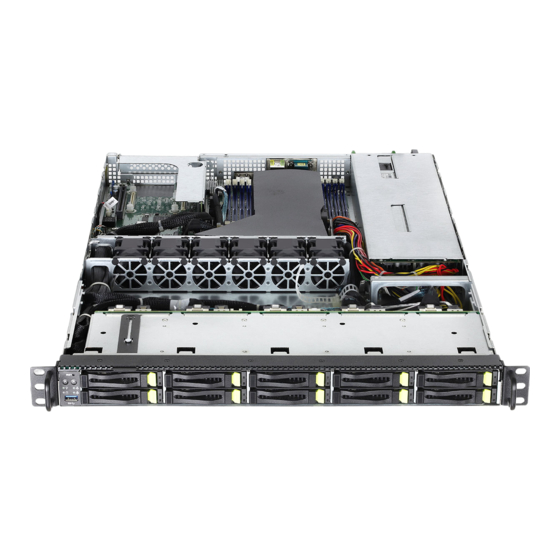
Page 9: Internal Features
1U10E-ROME/2T 2.2 Internal Features... - Page 10 Description Server Board (ROMED8QM-2T) LAN Mezzanine Card Riser Board x16 (for PCIE6 slot on the server board) 2 x Power Supply Units System Fan1, 4056 System Fan2, 4056 System Fan3, 4056 System Fan4, 4056 System Fan5, 4056 System Fan6, 4056 Power Distribution Board (PDB) Backplane Board (BPB) Front Panel Board (FPB)
-
Page 11: System Front Panel
1U10E-ROME/2T 2.3 System Front Panel HDD10 HDD2 HDD4 HDD6 HDD8 HDD1 HDD3 HDD9 HDD5 HDD7 Description Control Panel Buttons and LEDs 1 x USB 3.0 Port 10 x 2.5" Hot-Swap HDD Trays 2.4 System Rear Panel Description 2 x Power Supply Units... -
Page 12: Front Control Panel Buttons And Leds
2.5 Front Control Panel Buttons and LEDs Front Control Panel Description System Reset Button Power Button NMI (Nonmaskable Interrupt) Button Power LED LAN1 Activity LED LAN2 Activity LED USB 3.0 Port *Please be noted that the functions are supported depending on the type of the server board. NMI (Nonmaskable Interrupt) Button Press the NMI button with a paper clip or pin to generate a nonmaskable interrupt and to put the server in a halt state for examination. - Page 13 1U10E-ROME/2T Status LED Definitions Power LED Status Description Green Power on Power off LAN1, LAN2 LED Status Description Amber Link between system and network or no access Blinking Amber Network access...
-
Page 14: Drive Tray Leds
2.6 Drive Tray LEDs Description HDD Activity LED HDD Status LED Status LED Definitions HDD Activity LED Status Description Solid Green HDD present, no activity Blinking Green HDD accessing / RAID rebuild (with HDD Status LED blinking Red alternatively) HDD not present HDD Status LED Status Description... -
Page 15: Chapter 3 Hardware Installation And Maintenance
1U10E-ROME/2T Chapter 3 Hardware Installation and Maintenance This chapter helps you assemble the chassis and install components. Before You Begin Before you work with the server, pay close attention to the “Important Safety Instructions” at the beginning of this manual. -
Page 16: Server Top Cover
3.1 Server Top Cover Removing the Server Top Cover 1. Before removing the top cover, power off the server and unplug the power cord. 2. The system must be operated with the chassis top cover installed to ensure proper cooling. 1. - Page 17 1U10E-ROME/2T Installing the Server Top Cover 1. Lower the top cover on the chassis, making sure the side latches align with the cutouts. Slide the top cover toward the front. 2. Press down on the latches and slide the top cover into place.
-
Page 18: Hard Drive
3.2 Hard Drive Removing Hard Drive Trays from the Chassis 1. Press the locking lever latch on the drive tray to unlock the retention lever. 2. Rotate the lever out and away from the module bay and pull the hard drive out of the HDD tray. - Page 19 1U10E-ROME/2T Installing a Hard Drive to the Hard Drive Tray 1. Engage two embossed pins into the side dimples on the tray. 2. Carefully push down the other side of the tray until the other two embossed pins and side dimples lock into place.
-
Page 20: System Fan
3.3 System Fan Replacing the Simple-Swap Fan 1. Unplug the fan connecter and remove the failed fan. 2. Align the mounting holes on the fan bar with the fan mounts on the replacement fan corners. 3. Gently place the fan on the fan bar. Make sure the fan is well seated. 4. -
Page 21: Server Board
1U10E-ROME/2T 3.4 Server Board Follow the steps below to install the server board to the chassis. 1. Hold the server board only by the edges. 2. Gently place the server board into the chassis. Sit the server board on the server board tray. -
Page 22: Add-On Card
3.5 Add-on Card 1. You can install an add-on card to the chassis only when you have a riser card installed on the server board. 2. Before installing the add-on card, power off the server and unplug the power cord. Removing the Blanking Plate from the Chassis 1. - Page 23 1U10E-ROME/2T Installing the Add-on Card Before installing an add-on card, you need to install a mezzaine card and a riser card first. Please refer to the followings for instructions. 1. Install the add-on card to the assembly. 2. Secure the add-on card to the assembly with the screw.
-
Page 24: Mezzanine Card
3.6 Mezzanine Card Before installing a Mezzanine card, please remove the riser-card assembly from the chassis first. 1. Remove the screws that secure the blanking plate on the chassis. Keep the screws for later use. . 2. Slide the blanking plate out sideways. - Page 25 1U10E-ROME/2T Install the four spacer supports into the server board around the mezzanine card slot. Note: Please contact the ASRockRack Technical Support Team for more information about the mezzanine adapter card and the supported mezzzaine cards. 4. Gently insert the mezzanine card into the mezzanine card slot.
-
Page 26: Installing The Cpu
Appendix A Installing the CPU 1. Before you insert the CPU into the socket, please check if the PnP cap is on the socket, if the CPU surface is unclean, or if there are any bent pins in the socket. Do not force to insert the CPU into the socket if above situation is found. - Page 27 1U10E-ROME/2T...
- Page 28 Carr ier Frame with CPU Rail Frame Please make sure that the carrier frame with CPU is closely attached to the rail frame while inserting it. Install the carrier frame with CPU. Don’t separate them.
- Page 29 1U10E-ROME/2T...
-
Page 30: Installation Of Memory Modules (Dimm)
Installation of Memory Modules (DIMM)
Need help?
Do you have a question about the 1U10E-ROME/2T and is the answer not in the manual?
Questions and answers