Table of Contents
Advertisement
Quick Links
Advertisement
Table of Contents

Related Manuals for Global American 3307800


Summary of Contents for Global American 3307800
- Page 1 User’s Manual Single Board Computer 3307800 Version 1.0, June 2007...
- Page 2 Copyrights This manual is copyrighted and all rights are reserved. It does not allow any non authorization in copied, photocopied, translated or reproduced to any electronic or machine readable form in whole or in part without prior written consent from the manufacturer. In general, the manufacturer will not be liable for any direct, indirect, special, incidental or consequential damages arising from the use of inability to use the product or documentation, even if advised of the possibility of such damages.
- Page 3 Global American, INC. sales representative directly. To contact a Global American, INC. sales representative, please send an email to salesinfo@Globalamericaninc.com. The items listed below should all be included in the 3307800 package. 1 x 3307800 single board computer 1 x IDE cable...
-
Page 4: Table Of Contents
1.1.1 3307800 Expansion Options ................2 1.1.2 3307800 Features ....................2 1.2 3307800 O ....................2 VERVIEW 1.2.1 3307800 Overview Photo................... 3 1.2.2 3307800 Peripheral Connectors and Jumpers ..........3 1.2.3 Technical Specifications..................4 DETAILED SPECIFICATIONS ................7 2.1 D ....................... 8 IMENSIONS 2.1.1 Board Dimensions.................... - Page 5 2.5.11 HD Audio......................19 2.5.12 Timers......................20 2.5.13 RTC (Real Time Clock) .................. 20 2.5.14 Power Management ..................20 2.5.15 Hardware Monitor ..................20 2.6 3307800 PCI ................21 OMPONENTS 2.6.1 PCIe Bus Overview ..................21 2.6.2 PCIe x16 Expansion..................21 2.6.3 PCIe Switch......................
- Page 6 3307800 2.9.2 Global American, INC. Expansion PICMG 1.3 Backplanes ......30 2.9.3 Global American, INC. Chassis............... 31 UNPACKING ......................32 3.1 A ..................33 STATIC RECAUTIONS 3.2 U ......................33 NPACKING 3.2.1 Unpacking Precautions..................33 3.3 U ................... 34 NPACKING HECKLIST 3.3.1 Package Contents.....................
- Page 7 3307800 4.3.3 LAN Connectors....................70 INSTALLATION ....................72 5.1 A ..................73 STATIC RECAUTIONS 5.2 I ................74 NSTALLATION ONSIDERATIONS 5.2.1 Installation Notices ..................74 5.2.2 Installation Checklist ..................75 5.3 U ......................76 NPACKING 5.3.1 Unpacking Precautions..................76 5.4 CPU, CPU C DIMM I ..........
- Page 8 3307800 A.2 DIO C ................... 102 ONNECTOR INOUTS A.3 A ................102 SSEMBLY ANGUAGE AMPLES A.3.1 Enable the DIO Input Function..............103 A.3.2 Enable the DIO Output Function ..............103 WATCHDOG TIMER ..................105 ADDRESS MAPPING...................110 C.1 A ......................111 DDRESS C.2 1...
- Page 9 3307800 List of Figures Figure 1-1: 3307800 Overview [Front View] ................3 Figure 2-1: 3307800 Dimensions (mm) ..................8 Figure 2-2: External Interface Panel Dimensions (mm) .............9 Figure 2-3: Data Flow Block Diagram ..................10 Figure 2-4: SO-DIMM Sockets.....................11 Figure 2-5: PCI Golden Finger Connection ................15 Figure 2-6: USB Golden Finger ....................16...
- Page 10 Figure 4-14: TV Connector Pinout Locations ................64 Figure 4-15: USB Connector Pinout Locations ................65 Figure 4-16: VGA Connector Pinout Locations ................67 Figure 4-17: 3307800 External Peripheral Interface Connector ..........68 Figure 4-18: PS/2 Pinout and Configuration ................68 Figure 4-19: RJ-45 Ethernet Connector ..................71 Figure 5-1: Make sure the CPU socket retention screw is unlocked........78...
- Page 11 Table 2-1: Power Consumption ....................29 Table 2-2: Compatible Global American, INC. PICMG 1.3 Backplanes ........30 Table 2-3: Compatible Global American, INC. Chassis....Error! Bookmark not defined. Table 3-1: Package List Contents ....................35 Table 3-2: Package List Contents ........... Error! Bookmark not defined.
- Page 12 3307800 Table 5-2: Clear CMOS Jumper Settings...................83 Table 5-3: Global American, INC. Provided Cables..............86 Page xiii...
- Page 13 3307800 Glossary AC ’97 Audio Codec 97 Hard Disk Drive ACPI Advanced Configuration and Integrated Data Electronics Power Interface Input/Output Advanced Power Management ICH4 I/O Controller Hub 4 ARMD ATAPI Removable Media Device L1 Cache Level 1 Cache ASKIR Shift Keyed Infrared...
- Page 15 THIS PAGE IS INTENTIONALLY LEFT BLANK Page xvi...
-
Page 16: Introduction
3307800 Chapter Introduction Page 1... -
Page 17: Overview
1.1.1 3307800 Expansion Options The 3307800 PICMG 1.3 form factor enables PCIe x16, PCIe x1 and PCI expansion cards to easily be added to the PICMG 1.3 compatible backplane the 3307800 is installed on. -
Page 18: 3307800 Overview Photo
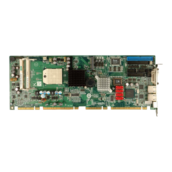
3307800 1.2.1 3307800 Overview Photo The 3307800 has a wide variety of peripheral interface connectors. Figure 1-1 is a labeled photo of the peripheral interface connectors on the 3307800. Figure 1-1: 3307800 Overview [Front View] 1.2.2 3307800 Peripheral Connectors and Jumpers... -
Page 19: Technical Specifications
1 x TPM connector 1 x TV Out connector 3 x USB 2.0 connectors 1 x VGA connector The 3307800 has the following external peripheral interface connectors on the board rear panel. 2 x Ethernet connectors 1 x DVI-I connector... - Page 20 3307800 Super I/O ITE8712F DVI-D and VGA Dual Display TV (Composite, S-Video, Component) and DVI ATI Radeon Express 1250 graphic engine intergated in AMD 690G provides VGA/DVI-I/TV(S-Video, Composite, Component) interfaces AVIVO provides advanced scaling, color correction of video Graphics playback processing, H/W decoding(WMV9, MPEG2/MPEG4), 2D/3D H/W Accelerating Supports max.1080i HDTV format of YPbPr componet output...
-
Page 21: Table 1-1: Technical Specifications
3307800 One 8-bit digital input/output connector; 4-bit input/4-bit Digital I/O output Watchdog Timer Software programmable 1-255 sec. by super I/O One IrDA connector by Super I/O Infrared Power Supply ATX power 3.3V@0.77A, 5V@4.23A, 5Vsb@0.1A and 12V@2.53A Power Consumption (2.0 GHz AMDl® Turion 64x2 TL-60 with two 1GB 667 MHz DDR2 DIMMs running 2Dmark®... -
Page 22: Detailed Specifications
3307800 Chapter Detailed Specifications Page 7... -
Page 23: Dimensions
3307800 2.1 Dimensions 2.1.1 Board Dimensions The dimensions of the board are listed below: Length: 338.58mm Width: 126.39mm Figure 2-1: 3307800 Dimensions (mm) Page 8... -
Page 24: External Interface Panel Dimensions
3307800 2.1.2 External Interface Panel Dimensions External peripheral interface connector panel dimensions are shown in Figure 2-2. Figure 2-2: External Interface Panel Dimensions (mm) 2.2 Data Flow Figure 2-3 shows the data flow between the two on-board chipsets and other components installed on the motherboard and described in the following sections of this chapter. -
Page 25: Compatible Processors
3307800 Figure 2-3: Data Flow Block Diagram 2.3 Compatible Processors 2.3.1 Supported Processors The 3307800 supports the following AMD Socket S1 processors AMD Turion™ 64 X2 dual-core mobile processor Mobile AMD Sempron™ processor Page 10... -
Page 26: Ddr2 Memory Controller
3307800 2.3.2 DDR2 Memory Controller All processors supported by the 3307800 CPU card have their own DDR2 memory controller. The DDR2 controller has the following features: Low-latency, high-bandwidth 667MHz 128-bit DDR2 SDRAM controller Supports up to two un-buffered DDR2 SO-DIMM... -
Page 27: Processor Power Management
3307800 2.3.4 Processor Power Management The supported processors have the following power management features: Multiple low-power states including Deeper Sleep (C1E with AltVID) System Management Mode (SMM) ACPI compliant, including support for processor performance states AMD PowerNow!™ technology is designed to dynamically switch between multiple low-power states based on application performance requirements. -
Page 28: Display Support
3307800 Support for OpenGL format for Indirect Vertices in Vertex Walker Motion video acceleration features on the AMD 690G include: Enhanced MPEG-2 hardware decode acceleration MPEG-4 decode support Hardware acceleration for WMV9 playback Supports top quality DVD and time-shifted SDTV/HDTV television playback with low CPU usage 2.4.3 Display Support... -
Page 29: Ati Sb600 Southbridge Chipset
3307800 Supports a TMDS interface, enabling DVI <1650 Mbps/channel with 165 MHz pixel clock rate per link HDCP 1.1 support on data stream with on-chip key storage 2.5 ATI SB600 Southbridge Chipset 2.5.1 CPU Interface The ATI SB600 Southbridge chipset supports the following AMD Socket S1 processors: AMD Turion™... -
Page 30: Usb Controllers
USB full-speed and low-speed signaling are enabled with the integrated Universal Host Controller Interface (UHCI) controllers. Six of the ten USB ports are implemented on the 3307800 CPU card. The remaining four USB ports can be implemented on the backplane. The USB controller supports the following: USB 1.1 (“Low Speed”, “Full Speed”) and 2.0 (“High Speed”) -
Page 31: Smbus Controller
3307800 Figure 2-6: USB Golden Finger 2.5.5 SMBus Controller The ATI SB600 southbridge chipset SMBus Controller is SMBus Rev. 2.0 compliant and supports SMBALERT # signal / GPIO. 2.5.6 Interrupt Controller The ATI SB600 southbridge interrupt controller supports the following:... -
Page 32: Lpc Host Bus Controller
2.5.9 SATA II AHCI Controller The integrated SATA controllers on the ATI SB600 Southbridge supports four SATA II drives on the 3307800 with independent DMA operations. The SATA controller supports the following: Four SATA ports, complying with SATA 2.0 specifications SATA II 3.0GHz PHY, with backward compatibility with 1.5GHz... -
Page 33: Ide Controller
3307800 Figure 2-7: SATA Connectors 2.5.10 IDE Controller The ATI SB600 southbridge IDE controller is interfaced to a single IDE connector. The IDE controller has the following specifications. Single PATA channel support Support PIO, multi-word DMA, and Ultra DMA 33/66/100/133 modes... -
Page 34: Hd Audio
3307800 2.5.11 HD Audio The 3307800 onboard audio connector can connect to an optional audio kit through an onboard audio connector. The codec on the optional audio kit is connected to the ATI SB600 audio controller through the High Definition audio. Supported HD Audio features are... -
Page 35: Timers
3307800 2.5.12 Timers The ATI SB600 south bridge has the following timers 8254-compatible timer Microsoft High Precision Event Timer (HPET) ACPI power management timer 2.5.13 RTC (Real Time Clock) 256 bytes of battery backed RAM is provided by the real time clock (RTC) integrated into the ATI SB600. -
Page 36: 3307800 Pcie Bus Components
Four PCIe x1 expansion cards on a compatible backplane Two PCIe GbE connections through two Broadcom controllers One Mini PCIe expansion device on the 3307800 2.6.2 PCIe x16 Expansion The AMD 690G northbridge chipset has one PCIe x16 port reserved for a PCIe x16 graphics card. -
Page 37: Pcie Switch
PCI Express Base Specification Revision 1.1 compliant 2.6.4 PCIe x1 Expansion The 3307800 has four PCIe x1 expansion channels interfaced to four PCIe x1 connectors on a backplane through a golden finger on the bottom of the CPU card. Two of the expansion PCIe x1 lanes come from the AMD 690G Northbridge chipset and two PCIe x1 lanes come from the IDT 89HPES8T5 PCIe switch. -
Page 38: Pcie Gbe Ethernet
3307800 Figure 2-12: PCIe x1 Golden Finger (Four Lanes) 2.6.5 PCIe GbE Ethernet Two PCIe x1 lanes from the IDT 89HPES8T5 PCIe switch are connected to two Broadcom BCM5787M PCIe GbE controllers shown in Figure 2-13 below. Figure 2-13: Broadcom PCI GbE Controllers The Broadcom BCM5787M is a 10/100/1000BASE-T Ethernet LAN controller. -
Page 39: Mini Pcie Card Socket
3307800 Integrated 10/100/1000BASE-T transceiver Automatic MDI crossover function PCIe v1.0a 10/100/1000BASE-T full/half-duplex MAC Wake on LAN support meeting the ACPI requirements Statistics for SNMP MIB II, Ethernet-like MIB, and Ethernet MIB (802.3z, clause 30) Serial EEPROM or serial flash support 2.6.6 Mini PCIe Card Socket... -
Page 40: Bios Chipset
USB booting support 2.7.3 TPM Module A TPM connector on the 3307800 is interfaced to the AMD SB600 southbridge through the LPC bus. The AMD SB600 southbridge supports TPM version 1.1 and TPM version 1.2 devices for enhanced security. Three TPM are available from Global American, INC.. The three Global American, INC. -
Page 41: Super I/O Chipset
3307800 For more information about these modules please refer to Chapter 3 or contact the 3307800 reseller or vendor. Alternatively, please contact Global American, INC. at salesinfo@Globalamericaninc.com. 2.7.4 Super I/O chipset The iTE IT8712F Super I/O chipset is connected to the AMD SB600 southbridge through the LPC bus. -
Page 42: Super I/O Enhanced Hardware Monitor
3307800 IrDa 1.0 and ASKIR protocols Figure 2-16: COM Connectors 2.7.4.3 Super I/O Enhanced Hardware Monitor The Super I/O Enhanced Hardware Monitor monitors three thermal inputs, VBAT internally, and eight voltage monitor inputs. These hardware parameters are reported in the BIOS and can be read from the BIOS Hardware Health Configuration menu. -
Page 43: Super I/O Infrared
The IrDA connector is compatible with the following standards: ASKIR 2.8 Environmental and Power Specifications 2.8.1 System Monitoring Three thermal inputs on the 3307800 Super I/O Enhanced Hardware Monitor monitor the following temperatures: CPU temperature System temperature System temperature 2... -
Page 44: Operating Temperature And Temperature Control
2.8.3 Power Consumption Table 2-1 shows the power consumption parameters for the 3307800 running 3D Mark® 2001 SE330 with a 2.0GHz AMD Turion 64x2 TL-60 processor and two 1.0GB 667MHz DDR2 DIMMs. -
Page 45: Global American, Inc. Expansion Picmg 1.3 Backplanes
3307800 2.9.2 Global American, INC. Expansion PICMG 1.3 Backplanes The backplanes listed in Table 2-2 are compatible with the 3307800 and can be used to develop highly integrated industrial applications. All of the backplanes listed below have 24-pin ATX connector and a 4-pin ATX connector. For more information about these backplanes please consult the Global American, INC. -
Page 46: Global American, Inc. Chassis
Global American, INC. chassis available for 3307800 system development are listed in Error! Reference source not found.. For more information about these chassis please consult the Global American, INC. catalog or contact your vendor, reseller or the Global American, INC. sales team at salesinfo@Globalamericaninc.com. Model... -
Page 47: Unpacking
3307800 Chapter Unpacking Page 32... -
Page 48: Anti-Static Precautions
When the 3307800 is unpacked, please do the following: Follow the anti-static precautions outlined in Section 3.1. Make sure the packing box is facing upwards so the 3307800 does not fall out of the box. Make sure all the components shown in Section 3.3 are present. -
Page 49: Unpacking Checklist
If some of the components listed in the checklist below are missing, please do not proceed with the installation. Contact the Global American, INC. reseller or vendor you purchased the 3307800 from or contact a Global American, INC. sales representative directly. To contact a Global American, INC. -
Page 50: Table 3-1: Package List Contents
3307800 KB/MS PS/2 Y-cable SATA cables SATA power cables Mini jumper Pack Quick Installation Guide Utility CD USB cable Table 3-1: Package List Contents Page 35... -
Page 51: Optional Items
3307800 3.4 Optional Items Audio kit (P/N: 1007760) CPU cooler (P/N: 2107703) FDD cable (P/N: 1208380) HDTV Cable Set comprises a S-Video cable and a TV-out cable (P/N: 1208410) TV-out extension cable with Composite / S-Video / Component output (Max.1080i... - Page 52 3307800 THIS PAGE IS INTENTIONALLY LEFT BLANK Page 37...
-
Page 53: Connector Pinouts
3307800 Chapter Connector Pinouts Page 38... -
Page 54: Peripheral Interface Connectors
Figure 4-1 shows the on-board peripheral connectors, rear panel peripheral connectors and on-board jumpers. Figure 4-1: Connector and Jumper Locations 4.1.2 Peripheral Interface Connectors Table 4-1 shows a list of the peripheral interface connectors on the 3307800. Detailed descriptions of these connectors can be found below. Connector Type... -
Page 55: Table 4-1: Peripheral Interface Connectors
3307800 Digital input/output connector 10-pin header DIO1 FDD connector 34-pin box header FDD1 Front panel connector 10-pin header F_PANEL1 IDE Interface connector 40-pin box header IDE1 Infrared (IrDA) connector 5-pin header Mini PCI socket 52-pin socket MINI-PCIE1 Parallel port connector... -
Page 56: External Interface Panel Connectors
3307800 4.1.3 External Interface Panel Connectors Table 4-2 lists the rear panel connectors on the 3307800. Detailed descriptions of these connectors can be found in Section 4.3 on page 68. Connector Type Label DVI connector DVI1 Ethernet connector RJ-45 LAN1... -
Page 57: Figure 4-2: Audio Connector Location (9-Pin)
3307800 Figure 4-2: Audio Connector Location (9-pin) PIN NO. DESCRIPTION PIN NO. DESCRIPTION SYNC BITCLK SDOUT PCBEEP SDIN RST# +12V Table 4-3: Audio Connector Pinouts Page 42... -
Page 58: Digital Input/Output (Dio) Connector
3307800 4.2.2 Digital Input/Output (DIO) Connector CN Label: DIO1 10-pin header (2x5) CN Type: See Figure 4-3 CN Location: CN Pinouts: See Table 4-4 The digital input/output connector is managed through a Super I/O chip. The DIO connector pins are user programmable. -
Page 59: Fan Connector (+12V)
3307800 PIN NO. DESCRIPTION PIN NO. DESCRIPTION Output 3 Output 2 Output 1 Output 0 Input 3 Input 1 Input 1 Input 0 Table 4-4: DIO Connector Connector Pinouts 4.2.3 Fan Connector (+12V) CPU_FAN1, SYS_FAN1 CN Label: CN Type: 3-pin header... -
Page 60: Floppy Disk Connector (34-Pin)
3307800 Figure 4-4: +12V Fan Connector Location PIN NO. DESCRIPTION GND Rotation Signal +12V Table 4-5: +12V Fan Connector Pinouts 4.2.4 Floppy Disk Connector (34-pin) FDD1 CN Label: CN Type: 34-pin header (2x17) CN Location: See Figure 4-5 CN Pinouts:... -
Page 61: Figure 4-5: 34-Pin Fdd Connector Location
3307800 The floppy disk connector is connected to a floppy disk drive. Figure 4-5: 34-pin FDD Connector Location PIN NO. DESCRIPTION PIN NO. DESCRIPTION REDUCE WRITE INDEX# MOTOR ENABLE A# DRIVE SELECT B# Page 46... -
Page 62: Front Panel Connector (14-Pin)
3307800 DRIVE SELECT A# MOTOR ENABLE B# DIRECTION# STEP# WRITE DATA# WRITE GATE# TRACK 0# WRITE PROTECT# READ DATA# SIDE 1 SELECT# DISK CHANGE# Table 4-6: 34-pin FDD Connector Pinouts 4.2.5 Front Panel Connector (14-pin) CN Label: F_PANEL1 CN Type:... -
Page 63: Figure 4-6: Front Panel Connector Pinout Locations (14-Pin)
3307800 Figure 4-6: Front Panel Connector Pinout Locations (14-pin) FUNCTION DESCRIPTION FUNCTION DESCRIPTION Power LED+ Speaker SPEAKER+ LED- Power PWRBTSW+ SPEAKER - Button PWRBTSW- Reset HDD LED IDE LED+ RESET+ IDE LED- RESET- Table 4-7: Front Panel Connector Pinouts (14-pin) -
Page 64: Ide Connector (40-Pin)
CN Label: IDE1 40-pin header (2x20) CN Type: See Figure 4-7 CN Location: CN Pinouts: See Table 4-8 One 40-pin IDE device connector on the 3307800 supports connectivity to two hard disk drives. Figure 4-7: IDE Device Connector Locations Page 49... -
Page 65: Infrared Interface Connector (5-Pin)
3307800 PIN NO. DESCRIPTION PIN NO. DESCRIPTION RESET# GROUND DATA 7 DATA 8 DATA 6 DATA 9 DATA 5 DATA 10 DATA 4 DATA 11 DATA 3 DATA 12 DATA 2 DATA 13 DATA 1 DATA 14 DATA 0 DATA 15... -
Page 66: Mini Pci Slot
3307800 Figure 4-8: Infrared Connector Pinout Locations PIN NO. DESCRIPTION IR-RX IR-TX Table 4-9: Infrared Connector Pinouts 4.2.8 Mini PCI Slot CN Label: MINI-PCIE1 CN Type: 124-pin Mini PCI Slot CN Location: See Figure 4-9 Page 51... - Page 67 3307800 See Table 4-10 CN Pinouts: The Mini PCI slot enables a Mini PCI expansion module to be connected to the board. Page 52...
-
Page 68: Figure 4-9: Mini Pci Slot Location
3307800 Figure 4-9: Mini PCI Slot Location Page 53... - Page 69 3307800 PIN NO. DESCRIPTION PIN NO. DESCRIPTION PINTD# VCC5 VCC3 PINTC# VCC3SB CLK_MPCI PCI_RST1# VCC3 PCI_REQ2# PCI_GNT2# VCC3 PAD31 PPME# PAD29 PAD30 PAD27 VCC3 PAD25 PAD28 PAD26 PC/BE3# PAD24 PAD23 PAD29 PAD21 PAD22 PAD19 PAD20 PPAR Page 54...
- Page 70 3307800 PIN NO. DESCRIPTION PIN NO. DESCRIPTION PAD17 PAD18 PC/BE2# PAD16 PIRDY# VCC3 PFRAME# PTRDY# SERR# PSTOP# VCC3 PERR# PDEVSEL# PC/BE1# PAD14 PAD15 PAD13 PAD12 PAD11 PAD10 PAD9 PAD8 PC/BE0# PAD7 VCC3 VCC3 PAD6 PAD5 PAD4 PAD2 PAD3 PAD0 VCC5...
-
Page 71: Parallel Port Connector
3307800 PIN NO. DESCRIPTION PIN NO. DESCRIPTION VCC3SB Table 4-10: Mini PCIe Slot Pinouts 4.2.9 Parallel Port Connector CN Label: LPT1 CN Type: 26-pin box header See Figure 4-10 CN Location: CN Pinouts: See Table 4-11 The 26-pin parallel port connector connects to a parallel port connector interface or some other parallel port device such as a printer. -
Page 72: Figure 4-10: Parallel Port Connector Location
3307800 Figure 4-10: Parallel Port Connector Location PIN NO. DESCRIPTION PIN NO. DESCRIPTION STROBE# DATA 0 DATA 1 DATA 2 DATA 3 DATA 4 DATA 5 DATA 6 DATA 7 ACKNOWLEDGE BUSY PAPER EMPTY PRINTER SELECT AUTO FORM FEED #... -
Page 73: Sata Drive Connectors
3307800 GROUND GROUND GROUND GROUND GROUND GROUND GROUND Table 4-11: Parallel Port Connector Pinouts 4.2.10 SATA Drive Connectors CN Label: SATA1, SATA2, SATA3, and SATA4 CN Type: 7-pin SATA drive connectors See Figure 4-11 CN Location: CN Pinouts: See Table 4-12 The two SATA drive connectors are each connected to a first generation SATA drive. -
Page 74: Figure 4-11: Sata Drive Connector Locations
3307800 Figure 4-11: SATA Drive Connector Locations PIN NO. DESCRIPTION Table 4-12: SATA Drive Connector Pinouts Page 59... -
Page 75: Serial Port Connector (Com1, Com 2)
3307800 4.2.11 Serial Port Connector (COM1, COM 2) COM1 and COM2 CN Label: CN Type: 10-pin header (2x5) CN Location: See Figure 4-12 CN Pinouts: See Table 4-13 The 10-pin serial port connector provides a second RS-232 serial communications channel. The COM 2 serial port connector can be connected to external RS-232 serial port devices. -
Page 76: Trusted Platform Module (Tpm) Connector
3307800 Receive Data (RXD) Request To Send (RTS) Transmit Data (TXD) Clear To Send (CTS) Data Terminal Ready (DTR) Ring Indicator (RI) Ground (GND) Ground (GND) Table 4-13: Serial Connector Pinouts 4.2.12 Trusted Platform Module (TPM) Connector CN Label: TPM1... -
Page 77: Figure 4-13: Tpm Connector Pinout Locations
3307800 Figure 4-13: TPM Connector Pinout Locations PIN NO. DESCRIPTION PIN NO. DESCRIPTION LCLK GND2 LFRAME# LRESET# LAD3 LAD2 LAD1 LAD0 GND3 SB3V SERIRQ Page 62... -
Page 78: Tv Out Connector
3307800 GND1 GLKRUN# LPCPD# LDRQ# Table 4-14: TPM Connector Pinouts 4.2.13 TV Out Connector CN Label: 6-pin header (2x3) CN Type: CN Location: See Figure 4-14 CN Pinouts: See Table 4-15 The 2x3 pin TV out connector connects to a TV output by using an S-Video or RCA connector. -
Page 79: Figure 4-14: Tv Connector Pinout Locations
3307800 Figure 4-14: TV Connector Pinout Locations S-Video Connector PIN NO. DESCRIPTION PIN NO. DESCRIPTION Luminance (Y) Chrominance (Pr) Chrominance (Pb) Table 4-15: TV Port Connector Pinouts Page 64... -
Page 80: Usb Connectors (Internal)
3307800 4.2.14 USB Connectors (Internal) USB1, USB2 and USB3 CN Label: CN Type: 8-pin header (2x4) CN Location: See Figure 4-15 CN Pinouts: See Table 4-16 The 2x4 USB pin connectors each provide connectivity to two USB 1.1 or two USB 2.0 ports. -
Page 81: Vga Connectors (Internal)
3307800 PIN NO. DESCRIPTION PIN NO. DESCRIPTION DATAN- DATAM+ DATAN+ DATAM- Table 4-16: USB Port Connector Pinouts 4.2.15 VGA Connectors (Internal) CN Label: 10-pin box header (2x4) CN Type: CN Location: See Figure 4-16 CN Pinouts: See Table 4-17 The 2x5 VGA pin connector provides connectivity to an external VGA port enabling the system to be connected to a standard CRT screen. -
Page 82: Figure 4-16: Vga Connector Pinout Locations
3307800 Figure 4-16: VGA Connector Pinout Locations PIN NO. DESCRIPTION PIN NO. DESCRIPTION L_RED CRT_DDC_DATA L_GREEN CRT_DDC_CLK L_BLUE 5VHSYNC 5VVSYNC Table 4-17: VGA Connector Pinouts Page 67... -
Page 83: External Peripheral Interface Connector Panel
3307800 4.3 External Peripheral Interface Connector Panel Figure 4-17 shows the 3307800 external peripheral interface connector (EPIC) panel. The 3307800 EPIC panel consists of the following: 1 x DVI connector 1 x PS/2 connector 2 x RJ-45 LAN connectors Figure 4-17: 3307800 External Peripheral Interface Connector 4.3.1 Keyboard/Mouse Connector... -
Page 84: Dvi Connector
3307800 DESCRIPTION KB DATA MS DATA KB CLOCK MS CLOCK Table 4-18: Keyboard Connector Pinouts 4.3.2 DVI Connector CN Label: DVI1 CN Type: DVI-I CN Location: See Figure 4-17 CN Pinouts: See Table 4-19 The 24-pin Digital Visual Interface (DVI) connector connects to high-speed, high-resolution digital displays. -
Page 85: Lan Connectors
CN Pinouts: See Table 4-20 The 3307800 is equipped with two built-in RJ-45 Ethernet controllers. The controllers can connect to the LAN through two RJ-45 LAN connectors. There are two LEDs on the connector indicating the status of LAN. The pin assignments are listed in the following... -
Page 86: Figure 4-19: Rj-45 Ethernet Connector
3307800 Figure 4-19: RJ-45 Ethernet Connector The RJ-45 Ethernet connector has two status LEDs, one green and one yellow. The green LED indicates activity on the port and the yellow LED indicates the port is linked. See Table 4-21. DESCRIPTION... -
Page 87: Installation
3307800 Chapter Installation Page 72... -
Page 88: Anti-Static Precautions
Electrostatic discharge (ESD) can cause serious damage to electronic components, including the 3307800. Dry climates are especially susceptible to ESD. It is therefore critical that whenever the 3307800, or any other electrical component is handled, the following anti-static precautions are strictly adhered to. -
Page 89: Installation Considerations
NOTE: The following installation notices and installation considerations should be read and understood before the 3307800 is installed. All installation notices pertaining to the installation of the 3307800 should be strictly adhered to. Failing to adhere to these precautions may lead to severe damage of the 3307800 and injury to the person installing the motherboard. -
Page 90: Installation Checklist
3307800 When working with the 3307800, make sure that it is disconnected from all power supplies and that no electricity is being fed into the system. Before and during the installation of the 3307800 DO NOT: Remove any of the stickers on the PCB board. These stickers are required for warranty validation. -
Page 91: Unpacking
When the 3307800 is unpacked, please do the following: Follow the anti-static precautions outlined in Section 5.1. Make sure the packing box is facing upwards so the 3307800 does not fall out of the box. Make sure all the components in the checklist shown in Chapter 3 are present. -
Page 92: Cpu, Cpu Cooling Kit And Dimm Installation
Running a CPU without a cooling kit may also result in injury to the user. The CPU, CPU cooling kit and DIMM are the most critical components of the 3307800. If one of these components is not installed the 3307800 cannot run. -
Page 93: Figure 5-1: Make Sure The Cpu Socket Retention Screw Is Unlocked
3307800 Step 1: Unlock the CPU retention screw. When shipped, the retention screw of the CPU socket should be in the unlocked position. If it is not in the unlocked position, use a screwdriver to unlock the screw. See Figure 5-1. -
Page 94: Cooling Kit 2107703 Installation
5.4.2 Cooling Kit 2107703 Installation Figure 5-2: Global American, INC. 2107703 Cooling Kit A Global American, INC. AMD Socket S1 CPU cooling kit (Figure 5-2) can be purchased separately. The cooling kit comprises a CPU heat sink and a cooling fan. -
Page 95: Figure 5-3: Cooling Kit Support Bracket
3307800 holes. (See Figure 5-3) Figure 5-3: Cooling Kit Support Bracket Step 11: Tighten the screws. Use a screwdriver to tighten the four screws. Tighten each nut a few turns at a time and do not over-tighten the screws. Step 12: Connect the fan cable. -
Page 96: So-Dimm Installation
Figure 5-5. Figure 5-5: SO-DIMM Installation Step 1: Locate the SO-DIMM socket. Place the 3307800 on an anti-static pad with the solder side facing up. Step 2: Align the SO-DIMM with the socket. The SO-DIMM must be oriented in such a way that the notch in the middle of the SO-DIMM must be aligned with the plastic bridge in the socket. -
Page 97: Jumper Settings
OPEN a jumper means removing the plastic clip from a jumper. Before the 3307800 is installed in the system, the jumpers must be set in accordance with the desired configuration. The jumpers on the 3307800 are listed in Table 5-1. Description... - Page 98 See Figure 5-6 Jumper Location: If the 3307800 fails to boot due to improper BIOS settings, the clear CMOS jumper clears the CMOS data and resets the system BIOS information. To do this, use the jumper cap to close pins 2 and 3 for a few seconds then reinstall the jumper clip back to pins 1 and 2.
-
Page 99: Chassis Installation
The 3307800 must be installed in a chassis with ventilation holes on the sides allowing airflow to travel through the heat sink surface. In a system with an individual power supply unit, the cooling fan of a power supply can also help generate airflow through the board surface. -
Page 100: Backplane Installation
5.6.2 Backplane Installation Before the 3307800 can be installed into the chassis, a backplane must first be installed. Please refer to the installation instructions that came with the backplane and the chassis to see how to install the backplane into the chassis. -
Page 101: Internal Peripheral Device Connections
5.7.2 ATA Flat Cable Connection The ATA 66/100 flat cable connects to the 3307800 to one or two IDE devices. To connect an IDE HDD to the 3307800 please follow the instructions below. -
Page 102: Audio Kit Installation
An optional audio kit that is separately ordered connects to the 9-pin audio connector on the 3307800. The audio kit consists of five audio jacks. One audio jack, Mic In, connects to a microphone. The remaining four audio jacks, Front-In, Front-Out, Rear-Out and subwoofer connect to four speakers including a subwoofer. -
Page 103: Fdd Cable Connection
Connect the audio devices. Connect the speakers and the subwoofer to the appropriate audio jack shown in Figure 5-8.Step 0: 5.7.4 FDD Cable Connection The FDD flat cable connects to the 3307800 to one FDD device. To connect an FDD to the 3307800 please follow the instructions below. Step 1: Locate the FDD connector. -
Page 104: Dual Rs-232 Cable Connection
3307800 Step 2: Insert the connector. Connect the FDD cable connector to the on-board connector. See Figure 5-9. A key on the front of the cable connector ensures it can only be inserted in one direction. Figure 5-9: FDD Cable Connection Step 3: Connect the cable to an FDD device. -
Page 105: Parallel Port Cable With Slot Bracket
3307800 Step 2: Insert the cable connectors. Insert one connector into each serial port box headers. See Figure 5-10. A key on the front of the cable connectors ensures the connector can only be installed in one direction. Figure 5-10: Dual RS-232 Cable Installation Step 3: Secure the bracket. -
Page 106: Figure 5-11: Lpt Cable Connection
3307800 a standard external LPT connector. To connect the LPT cable, please follow the steps below. Step 1: Locate the connector. The LPT connector location is shown in Chapter 4. Step 2: Align the connectors. Correctly align pin 1 on the cable connector with pin 1 on the PCIE-9452 LPT box-header connector. -
Page 107: Sata Drive Connection
Figure 5-12: Connect the LPT Device 5.7.7 SATA Drive Connection The 3307800 is shipped with two SATA drive cables and one SATA drive power cable. To connect the SATA drives to the connectors, please follow the steps below. Step 1: Locate the connectors. -
Page 108: Figure 5-13: Sata Drive Cable Connection
3307800 Figure 5-13: SATA Drive Cable Connection Step 3: Connect the cable to the SATA disk. Connect the connector on the other end of the cable to the connector at the back of the SATA drive. See Figure 5-14. Step 4: Connect the SATA power cable. -
Page 109: Usb Cable (Dual Port)
3307800 Figure 5-14: SATA Power Drive Connection 5.7.8 USB Cable (Dual Port) The 3307800 is shipped with a dual port USB 2.0 cable. To connect the USB cable connector, please follow the steps below. Step 1: Locate the connectors. The locations of the USB connectors are shown in Chapter 3. -
Page 110: External Peripheral Interface Connection
3307800 Figure 5-15: Dual USB Cable Connection Step 4: Attach the bracket to the chassis. The USB 2.0 connectors are attached to a bracket. To secure the bracket to the chassis please refer to the installation instructions that came with the chassis.Step 0:... -
Page 111: Dvi Display Device Connection
5.8.1 DVI Display Device Connection The 3307800 has a single female DVI-I connector on the external peripheral interface panel. The DVI-I connector is connected to a digital display device. To connect a digital display device to the 3307800, please follow the instructions below. -
Page 112: Lan Connection (Single Connector)
Chapter 4. Step 2: Align the connectors. Align the RJ-45 connector on the LAN cable with one of the RJ-45 connectors on the 3307800. See Figure 5-17. Figure 5-17: LAN Connection Step 3: Insert the LAN cable RJ-45 connector. Once aligned, gently insert the LAN cable RJ-45 connector into the onboard RJ-45 connector. -
Page 113: Ps/2 Y-Cable Connection
The 3307800 has a PS/2 connector on the external peripheral interface panel. The dual PS/2 connector is connected to the PS/2 Y-cable that came with the 3307800. One of the PS/2 cables is connected to a keyboard and the other to a mouse to the system. Follow the steps below to connect a keyboard and mouse to the 3307800. - Page 114 3307800 THIS PAGE IS INTENTIONALLY LEFT BLANK Page 99...
- Page 115 3307800 Page 100...
-
Page 116: Adio Interface
3307800 Appendix DIO Interface Page 101... -
Page 117: Dio Interface Introduction
3307800 A.1 DIO Interface Introduction The DIO connector on the 3307800 is interfaced to GIO ports on the iTE Super I/O chipset. The DIO has both 4-bit digital inputs and 4-bit digital outputs. The digital inputs and digital outputs are generally control signals that control the on/off circuit of external devices or TTL devices. -
Page 118: Enable The Dio Input Function
3307800 A.3.1 Enable the DIO Input Function The BIOS interrupt call INT 15H controls the digital I/O. An assembly program to enable digital I/O input functions is listed below. AX, 6F08H Sets the digital port as input Initiates the INT 15H BIOS call A.3.2 Enable the DIO Output Function... - Page 119 3307800 THIS PAGE IS INTENTIONALLY LEFT BLANK Page 104...
-
Page 120: Bwatchdog Timer
3307800 Appendix Watchdog Timer Page 105... - Page 121 3307800 NOTE: The following discussion applies to DOS environment. Global American, INC. support is contacted or the Global American, INC. website visited for specific drivers for more sophisticated operating systems, e.g., Windows and Linux. The Watchdog Timer is provided to ensure that standalone systems can always recover from catastrophic conditions that cause the CPU to crash.
- Page 122 3307800 Page 107...
- Page 123 3307800 NOTE: When exiting a program it is necessary to disable the Watchdog Timer, otherwise the system resets. Example program: ; INITIAL TIMER PERIOD COUNTER W_LOOP: AX, 6F02H ;setting the time-out value BL, 30 ;time-out value is 48 seconds ; ADD THE APPLICATION PROGRAM HERE EXIT_AP, 1 ;is the application over?
- Page 124 3307800 THIS PAGE IS INTENTIONALLY LEFT BLANK Page 109...
-
Page 125: Caddress Mapping
3307800 Appendix Address Mapping Page 110... -
Page 126: Address Map
3307800 C.1 Address Map I/O address Range Description 000-01F DMA Controller 020-021 Interrupt Controller 040-043 System time 060-06F Keyboard Controller 070-07F System CMOS/Real time Clock 080-09F DMA Controller 0A0-0A1 Interrupt Controller 0C0-0DF DMA Controller 0F0-0FF Numeric data processor 1F0-1F7 Primary IDE Channel... -
Page 127: Irq Mapping Table
3307800 C.3 IRQ Mapping Table IRQ0 System Timer IRQ8 RTC clock IRQ1 Keyboard IRQ9 ACPI IRQ2 Available IRQ10 IRQ3 COM2 IRQ11 LAN/USB2.0/SATA IRQ4 COM1 IRQ12 PS/2 mouse IRQ5 SMBus Controller IRQ13 IRQ6 IRQ14 Primary IDE IRQ7 Available IRQ15 Secondary IDE Table C-3: IRQ Mapping Table C.4 DMA Channel Assignments... - Page 128 3307800 THIS PAGE IS INTENTIONALLY LEFT BLANK Page 113...
-
Page 129: Draid Setup
3307800 Appendix RAID Setup Page 114... -
Page 130: Introduction
3307800 D.1 Introduction The AMD SB600 SATA RAID control can control serial ATA (SATA) disks and increase the data read/write speed and provide protection to data by distributing mirrored duplicates of data onto two disk drives (RAID 1). CAUTION! A configured RAID volume (which may consist of multiple hard drives) appears to an operating system as a contingent storage space. -
Page 131: Features And Benefits
3307800 CAUTION! Do not accidentally disconnect the SATA drive cables. Carefully route the cables within the chassis to avoid system down time. D.2 Features and Benefits Supports RAID levels 0, 1, and JBOD Supports connectivity to two disk drives Windows-based software for RAID management D.3 Accessing the AMD SB600 RAID Utility... - Page 132 3307800 Step 5: Press Ctrl-F. The following screen appears. Figure D-1: Accessing AMD RAID BIOS Utility Step 6: Delete RAID settings and partitions. Select Delete LD by pressing 3 in the Main Page menu above. Next, delete the drives individually.
- Page 133 3307800 Figure D-3: RAID Configuration Options Step 9: Configure the RAID. Use the configuration options in the RAID Configuration Options menu shown above to configure the RAID. Step 10: Select the RAID Mode. The following RAID configuration options are available.
- Page 134 3307800 Figure D-4: RAID Configuration Options Step 17: Exit the Define LD screen. To exit, press “Escape.” The Main Menu reappears. Step 18: Exit the Main Menu and reboot. When exiting the main menu, a prompt appears asking if the user wishes to reboot the system. Press “Y” to continue.
- Page 135 Any advice or comments about our products and service, or anything we can help you with please don’t hesitate to contact with us. We will do our best to support your products, projects and business. Address: Global American, Inc. 17 Hampshire Drive Hudson, NH 03051 Telephone: Toll Free (U.S. Only) 800-833-8999...
Need help?
Do you have a question about the 3307800 and is the answer not in the manual?
Questions and answers