Sign In
Upload
Manuals
Brands
Global American Manuals
Motherboard
3307800
Global American 3307800 Manuals
Manuals and User Guides for Global American 3307800. We have
1
Global American 3307800 manual available for free PDF download: User Manual
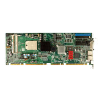
Global American 3307800 User Manual (135 pages)
Brand:
Global American
| Category:
Motherboard
| Size: 8.59 MB
Table of Contents
Table of Contents
4
1 Introduction
16
Overview
17
3307800 Expansion Options
17
3307800 Features
17
3307800 Overview Photo
18
3307800 Peripheral Connectors and Jumpers
18
Figure 1-1: 3307800 Overview [Front View]
18
Technical Specifications
19
Table 1-1: Technical Specifications
21
2 Detailed Specifications
22
Dimensions
23
Board Dimensions
23
Figure 2-1: 3307800 Dimensions (MM)
23
Figure 2-2: External Interface Panel Dimensions (MM)
24
Figure 2-3: Data Flow Block Diagram
25
DDR2 Memory Controller
26
Figure 2-4: SO-DIMM Sockets
26
Processor Electrical Interfaces
26
Acceleration Features
27
Amd 690G Northbridge Chipset
27
PCI Express Interface
27
Processor Power Management
27
Display Support
28
DVI Support
28
Multiple Display Features
28
TV out
28
A-Link Xpress II Interface to the Northbridge
29
Ati Sb600 Southbridge Chipset
29
CPU Interface
29
PCI Host Bus Controller
29
Figure 2-5: PCI Golden Finger Connection
30
USB Controllers
30
DMA Controller
31
Figure 2-6: USB Golden Finger
31
Interrupt Controller
31
Smbus Controller
31
LPC Host Bus Controller
32
SATA II AHCI Controller
32
Compatible Processors
25
Supported Processors
25
Data Flow
24
External Interface Panel Dimensions
24
Figure 2-8: IDE Connector
33
Figure 2-7: SATA Connectors
33
Figure 2-10: Pcie X16 Golden Finger
36
Figure 2-11: Pcie Switch
37
Pcie Switch
37
Pcie X1 Expansion
37
Figure 2-12: Pcie X1 Golden Finger (Four Lanes)
38
Figure 2-13: Broadcom PCI Gbe Controllers
38
Pcie Gbe Ethernet
38
Figure 2-14: Mini Pcie Socket
39
Lpc Bus Components
39
LPC Bus Overview
39
Mini Pcie Card Socket
39
BIOS Chipset
40
Figure 2-15: LPC BUS Components
40
TPM Module
40
Super I/O 16C550 Uarts
41
Super I/O Chipset
41
Super I/O LPC Interface
41
Figure 2-16: COM Connectors
42
Super I/O Enhanced Hardware Monitor
42
Super I/O Fan Speed Controller
42
Super I/O Keyboard Controller
42
Environmental and Power Specifications
43
Super I/O Infrared
43
System Monitoring
43
Expansion Options
44
Expansion Options Overview
44
Operating Temperature and Temperature Control
44
Power Consumption
44
Table 2-1: Power Consumption
44
Global American, INC. Expansion PICMG 1.3 Backplanes
45
Table 2-2: Compatible Global American, INC. PICMG 1.3 Backplanes
45
Global American, INC. Chassis
46
Figure 2-9: Audio Connector
34
HD Audio
34
Hardware Monitor
35
Power Management
35
RTC (Real Time Clock)
35
Timers
35
3307800 Pcie Bus Components
36
Pcie Bus Overview
36
Pcie X16 Expansion
36
IDE Controller
33
3 Unpacking
47
Anti-Static Precautions
48
Unpacking
48
Unpacking Precautions
48
Unpacking Checklist
49
Package Contents
49
Table 3-1: Package List Contents
50
Optional Items
51
Table 3-2: Package List Contents
51
4 Connector Pinouts
53
Figure 4-1: Connector and Jumper Locations
54
Table 4-2: Rear Panel Connectors
56
Figure 4-2: Audio Connector Location (9-Pin)
57
Figure 4-3: DIO Connector Connector Locations
58
Fan Connector (+12V)
59
Table 4-3: Audio Connector Pinouts
57
Digital Input/Output (DIO) Connector
58
Peripheral Interface Connectors
54
3307800 Layout
54
Table 4-1: Peripheral Interface Connectors
55
External Interface Panel Connectors
56
Internal Peripheral Connectors
56
Audio Connector
56
Table 4-4: DIO Connector Connector Pinouts
59
Figure 4-4: +12V Fan Connector Location
60
Figure 4-5: 34-Pin FDD Connector Location
61
Front Panel Connector (14-Pin)
62
Floppy Disk Connector (34-Pin)
60
Table 4-5: +12V Fan Connector Pinouts
60
Table 4-6: 34-Pin FDD Connector Pinouts
62
Figure 4-6: Front Panel Connector Pinout Locations (14-Pin)
63
Table 4-7: Front Panel Connector Pinouts (14-Pin)
63
Table 4-8: IDE Connector Pinouts
65
Figure 4-8: Infrared Connector Pinout Locations
66
Mini PCI Slot
66
Table 4-9: Infrared Connector Pinouts
66
Figure 4-9: Mini PCI Slot Location
68
Parallel Port Connector
71
Table 4-10: Mini Pcie Slot Pinouts
71
Figure 4-10: Parallel Port Connector Location
72
SATA Drive Connectors
73
Table 4-11: Parallel Port Connector Pinouts
73
Figure 4-11: SATA Drive Connector Locations
74
Table 4-12: SATA Drive Connector Pinouts
74
Figure 4-12: Serial Connector Pinout Locations
75
Table 4-13: Serial Connector Pinouts
76
Trusted Platform Module (TPM) Connector
76
Figure 4-13: TPM Connector Pinout Locations
77
Table 4-14: TPM Connector Pinouts
78
TV out Connector
78
Figure 4-14: TV Connector Pinout Locations
79
Table 4-15: TV Port Connector Pinouts
79
Figure 4-15: USB Connector Pinout Locations
80
USB Connectors (Internal)
80
Table 4-16: USB Port Connector Pinouts
81
VGA Connectors (Internal)
81
Figure 4-16: VGA Connector Pinout Locations
82
Table 4-17: VGA Connector Pinouts
82
External Peripheral Interface Connector Panel
83
Figure 4-17: 3307800 External Peripheral Interface Connector
83
Figure 4-18: PS/2 Pinout and Configuration
83
Keyboard/Mouse Connector
83
DVI Connector
84
Table 4-18: Keyboard Connector Pinouts
84
LAN Connectors
85
Serial Port Connector (COM1, COM 2)
75
Figure 4-7: IDE Device Connector Locations
64
IDE Connector (40-Pin)
64
Infrared Interface Connector (5-Pin)
65
Table 4-19: DVI Connector Pinouts
85
Table 4-20: LAN Pinouts
85
Figure 4-19: RJ-45 Ethernet Connector
86
Table 4-21: RJ-45 Ethernet Connector Leds
86
5 Installation
87
Anti-Static Precautions
88
Installation Considerations
89
Installation Notices
89
Installation Checklist
90
Unpacking
91
Unpacking Precautions
91
Cpu, Cpu Cooling Kit and DIMM Installation
92
AMD Socket S1 CPU Installation
92
Figure 5-1: Make Sure the CPU Socket Retention Screw Is Unlocked
93
Cooling Kit 2107703 Installation
94
Figure 5-2: Global American, INC. 2107703 Cooling Kit
94
Figure 5-3: Cooling Kit Support Bracket
95
Figure 5-4: Connect the Cooling Fan Cable
95
Figure 5-5: SO-DIMM Installation
96
Table 5-1: Jumpers
97
Figure 5-6: Clear CMOS Jumper
99
Backplane Installation
100
CPU Card Installation
100
ATA Flat Cable Connection
101
Internal Peripheral Device Connections
101
Peripheral Device Cables
101
Audio Kit Installation
102
Figure 5-7: IDE Cable Connection
102
FDD Cable Connection
103
Figure 5-8: Audio Kit Connection
103
Dual RS-232 Cable Connection
104
Chassis Installation
99
Airflow
99
Figure 5-9: FDD Cable Connection
104
Figure 5-11: LPT Cable Connection
106
Figure 5-12: Connect the LPT Device
107
SATA Drive Connection
107
Figure 5-13: SATA Drive Cable Connection
108
Figure 5-14: SATA Power Drive Connection
109
USB Cable (Dual Port)
109
External Peripheral Interface Connection
110
Figure 5-15: Dual USB Cable Connection
110
DVI Display Device Connection
111
Figure 5-16: DVI Connector
111
Figure 5-17: LAN Connection
112
LAN Connection (Single Connector)
112
PS/2 Y-Cable Connection
113
Figure 5-10: Dual RS-232 Cable Installation
105
Parallel Port Cable with Slot Bracket
105
SO-DIMM Installation
96
Jumper Settings
97
Clear CMOS Jumper
97
Figure 5-18: PS/2 Keyboard/Mouse Connector
113
Adio Interface
116
Dio Interface Introduction
117
Dio Connector Pinouts
117
Assembly Language Samples
117
Enable the DIO Input Function
118
Enable the DIO Output Function
118
Bwatchdog Timer
120
Caddress Mapping
125
Address Map
126
St Mb Memory Address Map
126
Irq Mapping Table
127
Dma Channel Assignments
127
Draid Setup
129
Introduction
130
Precautions
130
Features and Benefits
131
Accessing the Amd Sb600 Raid Utility
131
Advertisement
Advertisement
Related Products
Global American 3307555
Global American 3307562
Global American 3307389
Global American 3307810
Global American 3307880
Global American 3307740
Global American 3307940
Global American 3307840
Global American 3301450
Global American 3308050A
Global American Categories
Motherboard
Single board computers
Computer Hardware
Controller
PCI Card
More Global American Manuals
Login
Sign In
OR
Sign in with Facebook
Sign in with Google
Upload manual
Upload from disk
Upload from URL