Table of Contents
Advertisement
Quick Links
Advertisement
Table of Contents

Related Manuals for Global American PICMG 1.3 - 3307740


Summary of Contents for Global American PICMG 1.3 - 3307740
- Page 1 User’s Manual PICMG 1.3 - 3307740 Version 1.0...
- Page 2 Copyrights This manual is copyrighted and all rights are reserved. It does not allow any non authorization in copied, photocopied, translated or reproduced to any electronic or machine readable form in whole or in part without prior written consent from the manufacturer. In general, the manufacturer will not be liable for any direct, indirect, special, incidental or consequential damages arising from the use of inability to use the product or documentation, even if advised of the possibility of such damages.
- Page 3 Revision Date Version Changes 2007-03-23 1.00 Initial release Page i...
-
Page 4: Packing List
3307740 PICMG 1.3 CPU Card Packing List NOTE: If any of the components listed in the checklist below are missing, please do not proceed with the installation. Contact GLOBAL AMERICAN Sales Representative regarding 3307740 Tech Support The items listed below should all be included in the 3307740 package. 1 x 3307740 single board computer 1 x IDE cable 1 x SATA power cable... -
Page 5: Table Of Contents
Table of Contents INTRODUCTION....................19 1.1 I ......................20 NTRODUCTION 1.1.1 3307740 Benefits....................20 1.1.2 3307740 Features .................... 20 1.2 3307740 O ....................21 VERVIEW 1.2.1 3307740 Overview Photo................. 21 1.2.2 3307740 Peripheral Connectors and Jumpers ..........21 1.2.3 Technical Specifications................... 22 DETAILED SPECIFICATIONS ................ - Page 6 2.8.2 Operating Temperature and Temperature Control........... 47 2.8.3 Power Consumption..................47 2.9 E ....................48 XPANSION PTIONS 2.9.1 Expansion Options Overview................48 2.9.2 GLOBAL AMERICAN Expansion PICMG 1.3 Backplanes......48 2.9.3 GLOBAL AMERICAN Chassis ................ 49 UNPACKING ......................52 3.1 A ..................53 STATIC RECAUTIONS...
- Page 7 3.2 U ......................53 NPACKING 3.2.1 Unpacking Precautions..................53 3.3 U ................... 54 NPACKING HECKLIST 3.3.1 Package Contents..................... 54 3.3.2 Optional Items....................55 CONNECTOR PINOUTS..................58 4.1 P ..............59 ERIPHERAL NTERFACE ONNECTORS 4.1.1 3307740 Layout ....................59 4.1.2 Peripheral Interface Connectors ..............59 4.1.3 External Interface Panel Connectors...............
- Page 8 3307740 PICMG 1.3 CPU Card 5.1 A ..................93 STATIC RECAUTIONS 5.2 I ................94 NSTALLATION ONSIDERATIONS 5.2.1 Installation Notices ..................94 5.2.2 Installation Checklist ..................95 5.3 CPU, CPU C DIMM I ..........96 OOLING IT AND NSTALLATION 5.3.1 Socket 479 CPU Installation................96 5.3.3 DIMM Installation ...................
- Page 9 A.3 A ................127 SSEMBLY ANGUAGE AMPLES A.3.1 Enable the DIO Input Function..............127 A.3.2 Enable the DIO Output Function ..............127 WATCHDOG TIMER ..................129 ADDRESS MAPPING..................133 C.1 A ....................... 134 DDRESS C.2 1 MB M ................134 EMORY DDRESS C.3 IRQ M...
- Page 10 3307740 PICMG 1.3 CPU Card List of Figures Figure 1-1: 3307740 Overview [Front View] ................21 Figure 2-1: 3307740 Dimensions (mm) ..................26 Figure 2-2: External Interface Panel Dimensions (mm) ............27 Figure 2-3: Data Flow Block Diagram ..................28 Figure 2-4: 240-pin DDR2 DIMM Socket ..................31 Figure 2-5: PCIe x16 Golden Fingers..................31 Figure 2-6: Realtek PCI GbE Controllers..................39 Figure 2-7: Onboard USB Implementation .................41...
- Page 11 Figure 4-20: 3307740 External Peripheral Interface Connector ..........87 Figure 4-21: RJ-45 Ethernet Connector..................88 Figure 4-22: VGA Connector......................89 Figure 5-1: Make sure the CPU socket retention screw is unlocked ........97 Figure 5-2: Lock the CPU Socket Retention Screw..............98 Figure 5-6: Installing a DIMM .......................99 Figure 5-7: CF Card Installation ....................
- Page 12 Table 2-1: Supported Processors ....................29 Table 2-2: Supported HDD Specifications..................37 Table 2-3: Power Consumption ....................48 Table 2-4: Compatible GLOBAL AMERICAN PICMG 1.3 Backplanes ........49 Table 2-5: Compatible GLOBAL AMERICAN Chassis ...............51 Table 3-1: Package List Contents....................55 Table 3-2: Optional Items ......................57 Table 4-1: Peripheral Interface Connectors ................60...
- Page 13 Table 5-2: CF Card Setup Jumper Settings................103 Table 5-3: Clear CMOS Jumper Settings ................. 104 Table 5-4: FSB Setup Jumper Settings..................106 Table 5-5: LVDS Voltage Selection Jumper Settings.............. 107 Table 5-6: GLOBAL AMERICAN Provided Cables ..............109 Page xi...
- Page 14 3307740 PICMG 1.3 CPU Card Glossary AC ’97 Audio Codec 97 ACPI Advanced Configuration and Hard Disk Drive Power Interface Integrated Data Electronics Advanced Power Management Input/Output ICH4 I/O Controller Hub 4 ARMD ATAPI Removable Media Device ASKIR Shift Keyed Infrared L1 Cache Level 1 Cache Advanced Technology L2 Cache Level 2 Cache...
-
Page 15: Introduction
3307740 PICMG 1.3 CPU Card Chapter Introduction Page 19... -
Page 16: Introduction
3307740 PICMG 1.3 CPU Card 1.1 Introduction The 3307740 PICMG 1.3 CPU card is a Socket 479 Intel® Pentium® M or Intel® Celeron® M CPU platform. The 3307740 has a maximum front side bus (FSB) frequency of 533MHz and supports two 533MHz 1GB dual channel DDR2 memory modules. The 3307740 also comes with dual PCI Express (PCIe) Gigabit Ethernet (GbE) and has flexible storage options including support for two serial ATA (SATA) hard disk drives (HDD), two IDE HDD, a CompactFlash®... -
Page 17: 3307740 Overview
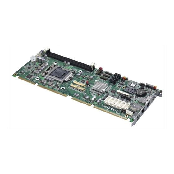
3307740 PICMG 1.3 CPU Card Two SATA drives with transfer rates of 1.5Gb/s supported High performance PCIe GbE Ethernet controllers Two USB 2.0 devices supported Multiple display options including CRT, 18-bit dual-channel LVDS and HDTV PICMG 1.3 form factor RoHS compliant 1.2 3307740 Overview 1.2.1 3307740 Overview Photo The 3307740 has a wide variety of internal and external peripheral connectors. -
Page 18: Technical Specifications
3307740 PICMG 1.3 CPU Card 1 x 8-bit general purpose Input/output (GPIO) connector 1 x IDE disk drive connector 1 x Infrared interface connector 1 x Inverter connector 1 x Keyboard connector 1 x LVDS connector 1 x Mouse connector 2 x Serial port connectors (internal COM 1 and COM 2 RS-232) 2 x Serial ATA (SATA) drive connectors 1 x Serial digital video out (SDVO) connector... - Page 19 3307740 PICMG 1.3 CPU Card Specification 3307740 Front Side Bus 400MHz or 533Mhz Northbridge: Intel® 915GM System Chipset Southbridge: Intel® ICH6M Two 240-pin DIMM sockets support two dual-channel 400MHz Memory or 533MHz DDR2 DIMMs with a maximum capacity of 1GB each ®...
-
Page 20: Table 1-1: Technical Specifications
3307740 PICMG 1.3 CPU Card Specification 3307740 CF Type II Software programmable 1-255 sec. by super I/O Watchdog Timer Power Supply ATX supported Temperature 0ºC – 60ºC (32ºF - 140ºF) Humidity (operating) 5%~95% non-condensing Dimensions (LxW) 338.58mm x 126.39mm Weight (GW/NW) 1100g/ 380g Table 1-1: Technical Specifications Page 24... -
Page 21: Detailed Specifications
3307740 PICMG 1.3 CPU Card Chapter Detailed Specifications Page 25... -
Page 22: Overview
3307740 PICMG 1.3 CPU Card 2.1 Overview This chapter describes the specifications and on-board features of the 3307740 in detail. 2.2 Dimensions 2.2.1 Board Dimensions The dimensions of the board are listed below: Length: 338.58mm Width: 126.39mm Figure 2-1: 3307740 Dimensions (mm) Page 26... -
Page 23: External Interface Panel Dimensions
3307740 PICMG 1.3 CPU Card 2.2.2 External Interface Panel Dimensions External peripheral interface connector panel dimensions are shown in Figure 2-2. Figure 2-2: External Interface Panel Dimensions (mm) 2.3 Data Flow Figure 2-3 shows the data flow between the two on-board chipsets and other components installed on the motherboard and described in the following sections of this chapter. -
Page 24: Compatible Processors
3307740 PICMG 1.3 CPU Card Figure 2-3: Data Flow Block Diagram 2.4 Compatible Processors 2.4.1 Compatible Processor Overview The 3307740 supports the following socket 479 processors: Intel® Pentium® M processors Intel® Celeron® M processors Page 28... -
Page 25: Intel ® 915Gm Northbridge Chipset
3307740 PICMG 1.3 CPU Card ® All the above processors communicate with the Intel 915GM northbridge chipset through a 533MHz or 400MHz front side bus (FSB). Compatible processors are listed in Table 2-1. Family CPU Speed Processor # Bus Speed Mfg Tech Stepping Cache Size Pentium®... -
Page 26: Intel 915Gm Memory Support
3307740 PICMG 1.3 CPU Card Front Side Bus (FSB) System Memory Interface Graphics Interface Direct Media Interface (DMI) ® 2.5.2 Intel 915GM Memory Support WARNING: Only DDR2 memory module can be installed on the 3307740. Do not install DDR memory modules. If a DDR memory module is installed on the 3307740, the 3307740 may be irreparably damaged. -
Page 27: Intel 915Gm Pcie X16
3307740 PICMG 1.3 CPU Card Figure 2-4: 240-pin DDR2 DIMM Socket ® 2.5.3 Intel 915GM PCIe x16 2.5.3.1 PCIe x16 Bus Overview The Intel® 915GM northbridge chipset has a dedicated 16-lane PCIe port for an external PCIe x16 graphics card. The PCIe x16 graphics card is installed on a compatible PICMG 1.3 backplane and interfaced to the northbridge through the two golden fingers shown in Figure 2-5. -
Page 28: Pcie X16 Expansion Options
3307740 PICMG 1.3 CPU Card 2.5.3.2 PCIe x16 Expansion Options The PCIe x16 can be interfaced to either one PCIe x16 graphics card or a single PCIe x1 expansion card on a compatible PICMG 1.3 backplane. 2.5.3.3 PCIe x16 Bus Specifications Some of the PCIe x16 bus specifications are listed below. -
Page 29: Intel 915Gm Analog Crt Support
3307740 PICMG 1.3 CPU Card ® 2.5.4.1 Intel 915GM Analog CRT Support A DB-15 VGA connector on the external peripheral interface connector panel is interfaced ® ® to the Intel 915GM graphics engine. The Intel 915GM internal graphics engine, with an integrated 400MHz RAMDAC and hot plug CRT support, supports analog CRT monitors with the following features: Supports max DAC frequency up to 400 MHz... -
Page 30: Intel 915Gm Tv Out Support
3307740 PICMG 1.3 CPU Card Supports down and center SSC via an SSC clock from an external SSC clock chip. Supports down spread of – 2.5% or center spread of ± -1.25% in reference 30-50 kHz modulation rate SSC must be disabled for LVDS port and CRT DAC single pipe simultaneous display mode. -
Page 31: Intel 915Gm Direct Media Interface (Dmi)
3307740 PICMG 1.3 CPU Card Two SDVO ports are supported Supports a variety display devices such as DVI, TV Out, LVDS, etc. Compliant with DVO specification 1.0 when combined with a DVI compliant external device and connector. Data sourced from either display Pipe A or Pipe B Supports single pipe simultaneous display with the DAC or LVDS ports Timings must match for both display Single pipe not supported with SSC on LVDS port... -
Page 32: Intel ® Ich6M Audio Codec '97 Controller
3307740 PICMG 1.3 CPU Card Complies with PCI Express Base Specification, Revision 1.0a Complies with PCI Local Bus Specification, Revision 2.3 and supports 33MHz PCI operations Supports ACPI Power Management Logic Contains: Enhanced DMA controller Interrupt controller Timer functions Integrated SATA host controller with DMA operations interfaced to two SATA connectors on the 3307740 Integrated IDE controller supports Ultra ATA 100/66/33 Supports the four USB 2.0 devices on the 3307740 with four UHCI controllers... -
Page 33: Intel ® Ich6M Ide Interface
3307740 PICMG 1.3 CPU Card ® 2.6.3 Intel ICH6M IDE Interface The integrated IDE interface on the ICH6M southbridge supports two IDE hard disks and ATAPI devices. PIO IDE transfers up to 16MB/s and Ultra ATA transfers of 100MB/s. The integrated IDE interface is able to support the following IDE HDDs: Ultra ATA/100, with data transfer rates up to 100MB/s Ultra ATA/66, with data transfer rates up to 66MB/s... -
Page 34: Intel Ich6M Low Pin Count (Lpc) Interface
3307740 PICMG 1.3 CPU Card ® 2.6.4 Intel ICH6M Low Pin Count (LPC) Interface The ICH6M LPC interface complies with the LPC 1.1 specifications. The LPC bus from the ICH6M is connected to the following components: BIOS chipset Super I/O chipset ®... -
Page 35: Figure 2-6: Realtek Pci Gbe Controllers
3307740 PICMG 1.3 CPU Card Figure 2-6: Realtek PCI GbE Controllers The Realtek RTL8110SC PCI GbE controllers combine a triple-speed IEEE 802.3 compliant Media Access Controller (MAC) with a triple-speed Ethernet transceiver, 32-bit PCI bus controller, and embedded memory. With state-of-the-art DSP technology and mixed-mode signal technology, they offer high-speed transmission over CAT 5 UTP cable or CAT 3 UTP (10Mbps only) cable. -
Page 36: Intel Ich6M Real Time Clock
3307740 PICMG 1.3 CPU Card Supports IEEE 802.1Q VLAN tagging Serial EEPROM 3.3/1.8/1.5V signaling, 5V PCI I/O tolerant 0.15µm CMOS process Transmit/Receive FIFO (8K/64K) support Supports power down/link down power saving Supports PCI Message Signaled Interrupt (MSI) ® 2.6.6 Intel ICH6M Real Time Clock 256 bytes of battery backed RAM is provided by the Motorola MC146818A real time clock (RTC) integrated into the ICH6M. -
Page 37: 3307740 Usb Implementation
3307740 PICMG 1.3 CPU Card 2.6.8.2 3307740 USB Implementation Two of the Intel® ICH6M USB ports are implemented on the 3307740. The two ports are connected to two external connectors. See Figure 2-7. Figure 2-7: Onboard USB Implementation 2.6.8.3 Backplane USB Implementation Four of the remaining six Intel®... -
Page 38: Intel Ich6M Pcie Bus Overview
3307740 PICMG 1.3 CPU Card ® 2.6.9 Intel ICH6M PCIe Bus Overview The Intel® ICH6M southbridge chipset has four PCIe x1 lanes. The four PCIe x1 lanes are interfaced through a golden finger on the bottom of the CPU card through the backplane to either four PCIe x1 expansion cards or one PCIe x4 expansion card. -
Page 39: Super I/O Chipset
3307740 PICMG 1.3 CPU Card Console redirection function support PXE (Pre-boot Execution Environment) support USB booting support The BIOS chipset is shown in Figure 2-10 below. Figure 2-10: BIOS Chipset 2.7.3 Super I/O chipset The iTE IT8712F Super I/O chipset is connected to the ICH7 southbridge through the LPC bus. -
Page 40: Super I/O Lpc Interface
3307740 PICMG 1.3 CPU Card Figure 2-11: Super I/O Chipset Some of the features of the iTE IT8712F chipset are listed below: LPC Interface PC98/99/2001, ACPI and LANDesk Compliant Enhanced Hardware Monitor Fan Speed Controller SmartGuardian Controller Single +5V Power Supply Two 16C550 UARTs for serial port control One IEEE 1284 Parallel Port Floppy Disk Controller... -
Page 41: Super I/O Enhanced Hardware Monitor
3307740 PICMG 1.3 CPU Card 2.7.3.3 Super I/O Enhanced Hardware Monitor The Super I/O Enhanced Hardware Monitor monitors three thermal inputs, VBAT internally, and eight voltage monitor inputs. These hardware parameters are reported in the BIOS and can be read from the BIOS Hardware Health Configuration menu. 2.7.3.4 Super I/O Fan Speed Controller The Super I/O fan speed controller enables the system to monitor the speed of the fan. -
Page 42: Tpm Connector
3307740 PICMG 1.3 CPU Card 2.7.4 TPM Connector The LPC bus is routed to a 20-pin TPM connector. The TPM connector facilitates the installation of a TPM. Three GLOBAL AMERICAN TPM are compatible with this connector and are listed below. 1007800: 20-pin Sinosun TPM... -
Page 43: Operating Temperature And Temperature Control
3307740 PICMG 1.3 CPU Card The 3307740 Super I/O Enhanced Hardware Monitor also monitors the following voltages internally: VBAT The 3307740 Super I/O Enhanced Hardware Monitor also monitors the following fan speeds: CPU Fan speed The values for the above environmental parameters are all recorded in the BIOS Hardware Health Configuration menu. -
Page 44: Expansion Options
Table 2-3: Power Consumption 2.9 Expansion Options 2.9.1 Expansion Options Overview A number of compatible GLOBAL AMERICAN Inc. PICMG 1.3 backplanes and chassis can be used to develop and expanded system. These backplanes and chassis are listed below. 2.9.2 GLOBAL AMERICAN Expansion PICMG 1.3 Backplanes The backplanes listed in Table 2-4 are compatible with the 3307740 and can be used to develop highly integrated industrial applications. -
Page 45: Global American Chassis
Single 1107890 Single 1107900 Single 1107910 Single 1107920 Dual 1107930 Single 1107940 Single Table 2-4: Compatible GLOBAL AMERICAN PICMG 1.3 Backplanes 2.9.3 GLOBAL AMERICAN Chassis GLOBAL AMERICAN chassis available for 3307740 system development are listed in Table 2-5. Page 49... - Page 46 3307740 PICMG 1.3 CPU Card more information about these chassis please consult sales team. Model Slot SBC Mounting Max Slots Backplanes 1407460 Full-size Wall 1107790 1107780 1107800 1401422 Full-size Wall 1107810 1107820 1107840 1107770 1404540 Full-size Wall 1107810 1107820 1104840 1107770 1404580 Full-size (4U)
-
Page 47: Table 2-5: Compatible Global American Chassis
1107910 1107920 1107930 1107940 1401032 Full-size Wall 1107740 1107860 1107870 1401412 Full-size Wall 1107740 1107880 1407660 Full-size Wall 1107840 1107770 1404570 Full-size (2U) Rack 1107750 1107850 1404552 Full-size (2U) Rack 1107750 1107850 Table 2-5: Compatible GLOBAL AMERICAN Chassis Page 51... -
Page 48: Unpacking
3307740 PICMG 1.3 CPU Card Chapter Unpacking Page 52... -
Page 49: Anti-Static Precautions
3307740 PICMG 1.3 CPU Card 3.1 Anti-static Precautions WARNING: Failure to take ESD precautions during the installation of the 3307740 may result in permanent damage to the 3307740 and severe injury to the user. Electrostatic discharge (ESD) can cause serious damage to electronic components, including the 3307740. -
Page 50: Unpacking Checklist
3.3 Unpacking Checklist Note: If some of the components listed in the checklist below are missing, please do not proceed with the installation. Contact a Global American sales representative directly at salesinfo@globalamericaninc.com. 3.3.1 Package Contents The 3307740 is shipped with the following components:... -
Page 51: Optional Items
The items listed in this section are optional items that must be ordered separately. Please contact your 3307740 vendor, distributor or reseller for more information or, contact Global American directly or Tech Support The following optional items are available for the 3307740. - Page 52 3307740 PICMG 1.3 CPU Card Quantity Item and Part Number Image VGA output SDVO card (P/N: 3907690) DVI output SDVO card (P/N: 3907680) 5-pin Wafer to PS/2 cable (P/N:1208370) LPT cable (P/N:1207760) FDD cable (P/N:1207764) TPM (Sinosun) (P/N:1007800) TPM (Winbond) (P/N:1007810) Page 56...
-
Page 53: Table 3-2: Optional Items
3307740 PICMG 1.3 CPU Card Quantity Item and Part Number Image TPM (Infineon) (P/N:1007790) Table 3-2: Optional Items Page 57... -
Page 54: Connector Pinouts
3307740 PICMG 1.3 CPU Card Chapter Connector Pinouts Page 58... -
Page 55: Peripheral Interface Connectors
3307740 PICMG 1.3 CPU Card 4.1 Peripheral Interface Connectors Section 4.1.2 shows peripheral interface connector locations. Section 4.1.2 lists all the peripheral interface connectors seen in Section 4.1.2. 4.1.1 3307740 Layout Figure 4-1 shows the on-board peripheral connectors, rear panel peripheral connectors and on-board jumpers. -
Page 56: Table 4-1: Peripheral Interface Connectors
3307740 PICMG 1.3 CPU Card Connector Type Label Fan connector (system) 3-pin wafer SYS_FAN1 Front panel connector 12-pin header Floppy disk connector 34-pin box header FDD1 GPIO connector 10-pin header DIO1 IDE Interface connector 40-pin box header IDE1 Infrared connector 5-pin header Inverter power connector 5-pin header... -
Page 57: External Interface Panel Connectors
3307740 PICMG 1.3 CPU Card 4.1.3 External Interface Panel Connectors Table 4-2 lists the rear panel connectors on the 3307740. Detailed descriptions of these connectors can be found in Section 4.3 on page 87 Connector Type Label Ethernet connector RJ-45 LAN1 Ethernet connector RJ-45... -
Page 58: Figure 4-2: Audio Connector Pinouts (10-Pin)
3307740 PICMG 1.3 CPU Card Figure 4-2: Audio Connector Pinouts (10-pin) PIN NO. DESCRIPTION PIN NO. DESCRIPTION AC97_SYNC AC97_BITCLK AC97_SDOUT AC97_PCBEEP AC97_SDIN AC97_RST# AC97_VCC AC97_GND AC97_12V AC97_GND Table 4-3: Audio Connector Pinouts (10-pin) Page 62... -
Page 59: Backlight Inverter Connector
3307740 PICMG 1.3 CPU Card 4.2.2 Backlight Inverter Connector CN Label: INVERTER1 CN Type: 6-pin wafer (1x6) CN Location: See Figure 4-3 CN Pinouts: See Table 4-4 The backlight inverter connector provides the backlight on the LCD display connected to the 3307740 with +12V of power. -
Page 60: Compact Flash Socket
3307740 PICMG 1.3 CPU Card PIN NO. DESCRIPTION +12V +12V BACKLIGHT ENABLE BACKLIGHT ADJUST GROUND GROUND Table 4-4: Panel Backlight Connector Pinouts 4.2.3 Compact Flash Socket CN Label: CF1 (solder side) CN Type: 50-pin header (2x25) CN Location: See Figure 4-4 See Table 4-5 CN Pinouts: A CF Type I or Type II memory card is inserted to the CF socket on the solder side of the... -
Page 61: Figure 4-4: Cf Card Socket Location
3307740 PICMG 1.3 CPU Card Figure 4-4: CF Card Socket Location Page 65... -
Page 62: Table 4-5: Cf Card Socket Pinouts
3307740 PICMG 1.3 CPU Card PIN NO. DESCRIPTION PIN NO. DESCRIPTION GROUND VCC-IN CHECK1 DATA 3 DATA 11 DATA 4 DATA 12 DATA 5 DATA 13 DATA 6 DATA 14 DATA 7 DATA 15 HDC_CS0# HDC_CS1 GROUND IOR# IOW# VCC_COM IRQ15 VCC_COM VCC_COM... -
Page 63: Fan Connector (+12V)
3307740 PICMG 1.3 CPU Card 4.2.4 Fan Connector (+12V) CN Label: CPU_FAN1, SYS_FAN1 CN Type: 3-pin header CN Location: See Figure 4-5 CN Pinouts: See Table 4-6 Two cooling fan connectors provide a 12V, 500mA current to a system cooling fan and a CPU cooling fan. -
Page 64: Floppy Disk Connector (34-Pin)
3307740 PICMG 1.3 CPU Card PIN NO. DESCRIPTION +12V Speed Detect Table 4-6: +12V Fan Connector Pinouts 4.2.5 Floppy Disk Connector (34-pin) CN Label: FDD1 CN Type: 34-pin box header (2x17) CN Location: See Figure 4-6 CN Pinouts: See Table 4-7 The floppy disk connector is connected to a floppy disk drive. -
Page 65: Gpio Connector
3307740 PICMG 1.3 CPU Card PIN NO. DESCRIPTION PIN NO. DESCRIPTION REDUCE WRITE INDEX# MOTOR ENABLE A# DRIVE SELECT B# DRIVE SELECT A# MOTOR ENABLE B# DIRECTION# STEP# WRITE DATA# WRITE GATE# TRACK 0# WRITE PROTECT# READ DATA# SIDE 1 SELECT# DISK CHANGE# Table 4-7: 34-pin FDD Connector Pinouts 4.2.6 GPIO Connector... -
Page 66: Front Panel Connector (12-Pin)
3307740 PICMG 1.3 CPU Card Figure 4-7: GPIO Connector Pinout Locations PIN NO. DESCRIPTION PIN NO. DESCRIPTION Table 4-8: GPIO Connector Pinouts 4.2.7 Front Panel Connector (12-pin) CN Label: CN Type: 12-pin header (2x6) CN Location: See Figure 4-8 Page 70... -
Page 67: Figure 4-8: Front Panel Connector Pinout Locations
3307740 PICMG 1.3 CPU Card CN Pinouts: See Table 4-9 The front panel connector connects to external switches and indicators to monitor and controls the motherboard. These indicators and switches include: Power button Reset button Power LED HDD LED Figure 4-8: Front Panel Connector Pinout Locations FUNCTION DESCRIPTION FUNCTION... -
Page 68: Ide Connector(40-Pin)
3307740 PICMG 1.3 CPU Card HDD LED HDD LED+ Reset RESET HDD LED- Table 4-9: Front Panel Connector Pinouts 4.2.8 IDE Connector(40-pin) CN Label: IDE1 CN Type: 40-pin box header (2x20) CN Location: See Figure 4-9 See Table 4-10 CN Pinouts: One 40-pin IDE device connector on the 3307740 supports connectivity to two hard disk drives. -
Page 69: Figure 4-9: Secondary Ide Device Connector Locations
3307740 PICMG 1.3 CPU Card Figure 4-9: Secondary IDE Device Connector Locations PIN NO. DESCRIPTION PIN NO. DESCRIPTION RESET# GROUND DATA 7 DATA 8 DATA 6 DATA 9 DATA 5 DATA 10 DATA 4 DATA 11 DATA 3 DATA 12 DATA 2 DATA 13 DATA 1... -
Page 70: Infrared Interface Connector (5-Pin)
3307740 PICMG 1.3 CPU Card HDC CS0# HDC CS1# HDD ACTIVE# GROUND Table 4-10: Secondary IDE Connector Pinouts 4.2.9 Infrared Interface Connector (5-pin) CN Label: CN Type: 5-pin header (1x5) CN Location: See Figure 4-10 CN Pinouts: See Table 4-11 The infrared interface connector supports both Serial Infrared (SIR) and Amplitude Shift Key Infrared (ASKIR) interfaces. -
Page 71: Keyboard Connector
3307740 PICMG 1.3 CPU Card PIN NO. DESCRIPTION IR-RX IR-TX Table 4-11: Infrared Connector Pinouts 4.2.10 Keyboard Connector CN Label: CN Type: 5-pin header (1x5) CN Location: See Figure 4-11 CN Pinouts: See Table 4-12 The keyboard connector can be connected to a standard PS/2 cable to add keyboard functionality to the system. -
Page 72: Lvds Lcd Connector
3307740 PICMG 1.3 CPU Card Figure 4-11: Keyboard Connector Location PIN NO. DESCRIPTION KEYBOARD CLOCK KEYBOARD DATA GROUND Table 4-12: Keyboard Connector Pinouts 4.2.11 LVDS LCD Connector CN Label: LVDS1 CN Type: 30-pin crimp (2x10) CN Location: See Figure 4-12 See Table 4-13 CN Pinouts: Page 76... -
Page 73: Figure 4-12: Lvds Lcd Connector Pinout Locations
3307740 PICMG 1.3 CPU Card The 30-pin LVDS LCD connector can be connected to single channel or dual channel, 18-bit LVDS panel. Figure 4-12: LVDS LCD Connector Pinout Locations PIN NO. DESCRIPTION PIN NO. DESCRIPTION GROUND GROUND LVDSA_Y0+ LVDSA_Y0- LVDSA_Y1+ LVDSA_Y1- LVDSA_Y2+ LVDSA_Y2-... -
Page 74: Mouse Connector
3307740 PICMG 1.3 CPU Card GROUND GROUND VCC_LVDS VCC_LVDS VCC_LVDS VCC_LVDS Table 4-13: LVDS LCD Port Connector Pinouts 4.2.12 Mouse Connector CN Label: CN Type: 5-pin header (1x5) CN Location: See Figure 4-11 See Table 4-12 CN Pinouts: The mouse connector can be connected to a standard PS/2 cable to add keyboard and mouse functionality to the system. -
Page 75: Parallel Port Connector
3307740 PICMG 1.3 CPU Card PIN NO. DESCRIPTION MOUSE CLOCK MOUSE DATA GROUND Table 4-14: Mouse Connector Pinouts 4.2.13 Parallel Port Connector CN Label: LPT1 CN Type: 26-pin box header CN Location: See Figure 4-14 See Table 4-15 CN Pinouts: The 26-pin parallel port connector connects to a parallel port connector interface or some other parallel port device such as a printer. -
Page 76: Figure 4-14: Parallel Port Connector Location
3307740 PICMG 1.3 CPU Card Figure 4-14: Parallel Port Connector Location PIN NO. DESCRIPTION PIN NO. DESCRIPTION STROBE# DATA 0 DATA 1 DATA 2 DATA 3 DATA 4 DATA 5 DATA 6 DATA 7 ACKNOWLEDGE BUSY PAPER EMPTY PRINTER SELECT AUTO FORM FEED # ERROR# INITIALIZE... -
Page 77: Sata Drive Connectors
3307740 PICMG 1.3 CPU Card 4.2.14 SATA Drive Connectors CN Label: SATA1 and SATA3 CN Type: 7-pin SATA drive connectors CN Location: See Figure 4-15 CN Pinouts: See Table 4-16 The two SATA drive connectors are each connected to a SATA drive. SATA drives transfer data at speeds as high as 150Mb/s. -
Page 78: Sdvo Connector
3307740 PICMG 1.3 CPU Card PIN NO. DESCRIPTION Table 4-16: SATA Drive Connector Pinouts 4.2.15 SDVO Connector CN Label: SDVO1 CN Type: 3-pin header (1x3) See Figure 4-16 CN Location: CN Pinouts: See Table 4-17 The SDVO connector is connected to and SDVO graphics card installed on the backplane. Figure 4-16: SDVO Connector Pinout Locations Page 82... -
Page 79: Serial Port Connector (Com1And Com2)
3307740 PICMG 1.3 CPU Card PIN NO. DESCRIPTION SDVO CLK SDVO DATA Table 4-17: SDVO Pinouts 4.2.16 Serial Port Connector (COM1and COM2) CN Label: COM1 and COM2 CN Type: 10-pin header (2x5) CN Location: See Figure 4-17 CN Pinouts: See Table 4-18 The 10-pin serial port connector provides a second RS-232 serial communications channel. -
Page 80: Trusted Platform Module (Tpm) Connector
3307740 PICMG 1.3 CPU Card Figure 4-17: COM1 and COM2 Connector Pinout Locations PIN NO. DESCRIPTION PIN NO. DESCRIPTION Data Carrier Detect (DCD) Data Set to Ready (DSR) Receive Data (RXD) Request to Send (RTS) Transmit Data (TXD) Clear to Sent (CTS) Data Terminal Ready (DTR) Ring Indicator (RI) Ground (GND) -
Page 81: Figure 4-18: Tpm Connector Pinout Locations
3307740 PICMG 1.3 CPU Card CN Pinouts: See Table 4-20 The Trusted Platform Module (TPM) connector secures the system on bootup. Figure 4-18: TPM Connector Pinout Locations PIN NO. DESCRIPTION PIN NO. DESCRIPTION LCLK GND2 LFRAME# LRESET# LAD3 LAD2 LAD1 LAD0 GND3 SB3V... -
Page 82: Tv Out Connector
3307740 PICMG 1.3 CPU Card LPCPD# LDRQ# Table 4-19: TPM Connector Pinouts 4.2.18 TV Out Connector CN Label: TVOUT1 CN Type: 6-pin header (2x3) See Figure 4-19 CN Location: CN Pinouts: See Table 4-20 The 2x3 pin TV out connector connects to a TV output by using an S-Video or RCA connector. -
Page 83: External Peripheral Interface Connector Panel
3307740 PICMG 1.3 CPU Card PIN NO. DESCRIPTION PIN NO. DESCRIPTION GREEN BLUE Table 4-20: TV OutConnector Pinouts 4.3 External Peripheral Interface Connector Panel Figure 4-20 shows the 3307740 rear panel. The 3307740 rear panel consists of two RJ-45 Ethernet connectors, a PS/2 keyboard connector a USB port and a VGA connector. These connectors are accessible when the 3307740 is installed in a chassis. -
Page 84: Usb Connector
3307740 PICMG 1.3 CPU Card DESCRIPTION DESCRIPTION TXA+ TXC- TXA- TXB- TXB+ TXD+ TXC+ TXD- Table 4-21: LAN Pinouts Figure 4-21: RJ-45 Ethernet Connector The RJ-45 Ethernet connector has two status LEDs, one green and one yellow. The green LED indicates activity on the port and the yellow LED indicates the port is linked. See Table 4-22. -
Page 85: Vga Connector
3307740 PICMG 1.3 CPU Card The 3307740 has a one external USB 2.0 port. The port connects to both USB 2.0 and USB 1.1 devices. PIN NO. DESCRIPTION DATA- DATA+ Table 4-23: USB Port Pinouts 4.3.3 VGA Connector CN Label: VGA1 CN Type: 15-pin Female... -
Page 86: Table 4-24: Vga Connector Pinouts
3307740 PICMG 1.3 CPU Card DESCRIPTION DESCRIPTION VCC / NC DDC DAT HSYNC VSYNC DDCCLK Table 4-24: VGA Connector Pinouts Page 90... - Page 87 3307740 PICMG 1.3 CPU Card THIS PAGE IS INTENTIONALLY LEFT BLANK Page 91...
-
Page 88: Installation
3307740 PICMG 1.3 CPU Card Chapter Installation Page 92... -
Page 89: Anti-Static Precautions
3307740 PICMG 1.3 CPU Card 5.1 Anti-static Precautions WARNING: Failure to take ESD precautions during the installation of the 3307740 may result in permanent damage to the 3307740 and severe injury to the user. Electrostatic discharge (ESD) can cause serious damage to electronic components, including the 3307740. -
Page 90: Installation Considerations
3307740 PICMG 1.3 CPU Card 5.2 Installation Considerations NOTE: The following installation notices and installation considerations should be read and understood before the 3307740 is installed. All installation notices pertaining to the installation of the 3307740 should be strictly adhered to. Failing to adhere to these precautions may lead to severe damage of the 3307740 and injury to the person installing the motherboard. -
Page 91: Installation Checklist
3307740 PICMG 1.3 CPU Card When working with the 3307740, make sure that it is disconnected from all power supplies and that no electricity is being fed into the system. Before and during the installation of the 3307740 DO NOT: Remove any of the stickers on the PCB board. -
Page 92: Cpu, Cpu Cooling Kit And Dimm Installation
3307740 PICMG 1.3 CPU Card USB device LAN connection 5.3 CPU, CPU Cooling Kit and DIMM Installation WARNING: A CPU should never be turned on without the specified cooling kit being installed. If the cooling kit (heat sink and fan) is not properly installed and the system turned on, permanent damage to the CPU, 3307740 and other electronic components attached to the system may be incurred. -
Page 93: Figure 5-1: Make Sure The Cpu Socket Retention Screw Is Unlocked
3307740 PICMG 1.3 CPU Card WARNING: CPUs are expensive and sensitive components. When installing the CPU please be careful not to damage it in anyway. Make sure the CPU is installed properly and ensure the correct cooling kit is properly installed. -
Page 94: Figure 5-2: Lock The Cpu Socket Retention Screw
3307740 PICMG 1.3 CPU Card Step 2: Inspect the CPU socket. Make sure there are no bent pins and make sure the socket contacts are free of foreign material. If any debris is found, remove it with compressed air. Step 3: Correctly Orientate the CPU. -
Page 95: Dimm Installation
3307740 PICMG 1.3 CPU Card 5.3.2 DIMM Installation WARNING: Using incorrectly specified DIMM may cause permanently damage the 3307740. Please make sure the purchased DIMM complies with the memory specifications of the 3307740. DIMM specifications compliant with the 3307740 are listed in Chapter 2. To install a DIMM into a DIMM socket, please follow the steps below and refer to Figure 5-3. -
Page 96: Cf Card Installation
3307740 PICMG 1.3 CPU Card in the socket. See Figure 5-3. Step 3: Insert the DIMM. Once properly aligned, the DIMM can be inserted into the socket. As the DIMM is inserted, the white handles on the side of the socket will close automatically and secure the DIMM to the socket. -
Page 97: Figure 5-7: Cf Card Installation
3307740 PICMG 1.3 CPU Card Figure 5-4: CF Card Installation Page 101... -
Page 98: Jumper Settings
3307740 PICMG 1.3 CPU Card 5.4 Jumper Settings NOTE: A jumper is a metal bridge used to close an electrical circuit. It consists of two or three metal pins and a small metal clip (often protected by a plastic cover) that slides over the pins to connect them. -
Page 99: Clear Cmos Jumper
3307740 PICMG 1.3 CPU Card The CF Card Setup jumper sets the CF Type I card or CF Type II cards as either the slave device or the master device. CF Card Setup jumper settings are shown in Table 5-2. AT Power Select Description Open... -
Page 100: Table 5-3: Clear Cmos Jumper Settings
3307740 PICMG 1.3 CPU Card Jumper Location: See Figure 5-7 If the 3307740 fails to boot due to improper BIOS settings, the clear CMOS jumper clears the CMOS data and resets the system BIOS information. To do this, use the jumper cap to close pins 2 and 3 for a few seconds then reinstall the jumper clip back to pins 1 and 2. -
Page 101: Fsb Setup Jumper
3307740 PICMG 1.3 CPU Card Figure 5-7: Clear CMOS Jumper 5.4.3 FSB Setup Jumper Jumper Label: 3-pin header Jumper Type: Jumper Settings: See Table 5-4 Jumper Location: See Figure 5-8 The clear FSB setup jumper enables a user to select the FSB speed on the 3307740. The FSB Setup jumper settings are shown in Table 5-3. -
Page 102: Lvds Voltage Selection
3307740 PICMG 1.3 CPU Card FSB Setup Description Short 1 – 2 100MHz Default Short 2 – 3 133MHz Table 5-4: FSB Setup Jumper Settings The location of the FSB Setup jumper is shown in Figure 5-7 below. Figure 5-8: FSB Setup Jumper Jumper 5.4.4 LVDS Voltage Selection WARNING: Permanent damage to the screen and 3307740 may occur if the wrong... -
Page 103: Figure 5-12: Lvds Voltage Selection Jumper Pinout Locations
3307740 PICMG 1.3 CPU Card Jumper Label: Jumper Type: 3-pin header See Table 5-5 Jumper Settings: Jumper Location: See Figure 5-9 The LVDS Voltage Selection jumper allows the LVDS screen voltage to be set. The LVDS Voltage Selection jumper settings are shown in Table 5-5. AT Power Select Description Short 1-2... -
Page 104: Chassis Installation
NOTE: Global American has a wide range of backplanes available. Please contact your 3307740 vendor, reseller or an Global American sales representative, or visit the Global American website www.globalamericaninc.com... -
Page 105: Cpu Card Installation
3307740 PICMG 1.3 CPU Card NOTE: GLOBAL AMERICAN has a wide range of backplanes available. Please contact your 3307740 a Global American sales representative. or visit the Global American website. website www.globalamericaninc.com to find out more about the available chassis. -
Page 106: Ide Cable Connection
3307740 PICMG 1.3 CPU Card LPT cable FDD cable 5-pin wafer-to-PS/2 cable for mouse or keyboard 7.1 channel audio kit 5.1 channel audio kit 5.6.2 IDE Cable Connection The IDE flat cable connects to the 3307740 to one or two IDE devices. To connect an IDE HDD to the 3307740 please follow the instructions below. -
Page 107: Channel Audio Kit Installation
This is an optional item that must be ordered separately. For further information please contact the nearest 3307740 distributor, reseller or vendor or contact an Global American sales representative directly. The optional 5.1 channel audio kit connects to the 10-pin audio connector on the 3307740. -
Page 108: Channel Audio Kit Installation
5.6.4 7.1 Channel Audio Kit Installation NOTE: This is an optional item that must be ordered separately. For further information please contact the nearest 3307740 distributor, reseller or vendor or contact an Global American sales representative directly. Page 112... -
Page 109: Figure 5-15: 5.1 Channel Audio Kit
3307740 PICMG 1.3 CPU Card The optional 7.1 channel audio kit connects to the 10-pin audio connector on the 3307740. The audio kit consists of five audio jacks. One audio jack, Mic In, connects to a microphone. The remaining four audio jacks, Line-In, Front-Out, Rear-Out, and Center Subwoofer, connect to speakers. -
Page 110: Fdd Cable Connection
3307740 PICMG 1.3 CPU Card 3307740, secure the audio kit bracket to the system chassis. Step 5: Connect the audio devices. Connect one speaker to the line-in audio jack, one speaker to the line-out audio jack and a microphone to the mic-in audio jack. Step 6: Install the driver. -
Page 111: Parallel Port Cable
3307740 PICMG 1.3 CPU Card Figure 5-13: FDD Cable Connection Step 3: Connect the cable to an FDD device. Connect the connector at the other end of the cable to an FDD device. Make sure that pin 1 on the cable corresponds to pin 1 on the connector. -
Page 112: Figure 5-17: Lpt Cable Connection
3307740 PICMG 1.3 CPU Card Figure 5-14: LPT Cable Connection Step 4: Attach the LPT connector bracket to the chassis. The LPT cable connector is connected to a standard external LPT interface connector. To secure the LPT interface connector to the chassis please refer to the installation instructions that came with the chassis. -
Page 113: Dual Rs-232 Cable Connection
3307740 PICMG 1.3 CPU Card Figure 5-15: Connect the LPT Device 5.6.7 Dual RS-232 Cable Connection The dual RS-232 cable consists of two connectors attached to two independent cables. Each cable is then attached to a D-sub 9 male connector that is mounted onto a bracket. To install the dual RS-232 cable, please follow the steps below. -
Page 114: Sata Drive Connection
3307740 PICMG 1.3 CPU Card Figure 5-16: Dual RS-232 Cable Installation Step 3: Secure the bracket. The dual RS-232 connector has two D-sub 9 male connectors secured on a bracket. To secure the bracket to the chassis please refer to the reference material that came with the chassis 5.6.8 SATA Drive Connection The 3307740 is shipped with two SATA drive cables and one SATA drive power cable. -
Page 115: Figure 5-20: Sata Drive Cable Connection
3307740 PICMG 1.3 CPU Card Figure 5-17: SATA Drive Cable Connection Step 3: Connect the cable to the SATA disk. Connect the connector on the other end of the cable to the connector at the back of the SATA drive. See Figure 5-18. Step 4: Connect the SATA power cable. -
Page 116: Wafer-To-Ps/2 Cable (Keyboard/Mouse Installation)
3307740 PICMG 1.3 CPU Card Figure 5-18: SATA Power Drive Connection 5.6.9 Wafer-to-PS/2 Cable (Keyboard/Mouse Installation) The optional wafer-to-PS/2 cable respectively connects the onboard keyboard wafer connector and the onboard mouse wafer connector to a PS/2 keyboard and a PS/2 mouse. -
Page 117: External Peripheral Interface Connection
3307740 PICMG 1.3 CPU Card Step 5: Connect the keyboard or mouse. Once the PS/2 connector is connected to the chassis, the wafer-to-PS/2 cable connected to the keyboard connector can be connected to the PS/2 connector on a keyboard and the wafer-to-PS/2 cable connected to the mouse connector can be connected to the PS/2 connector on a PS/2 mouse. -
Page 118: Usb Device Connection (Single Connector)
3307740 PICMG 1.3 CPU Card Figure 5-20: LAN Connection Step 3: Insert the LAN cable RJ-45 connector. Once aligned, gently insert the LAN cable RJ-45 connector into the onboard RJ-45 connector. 5.7.2 USB Device Connection (Single Connector) There are two external USB 2.0 connectors. Both connectors are perpendicular to the 3307740. -
Page 119: Vga Monitor Connection
3307740 PICMG 1.3 CPU Card Figure 5-21: USB Device Connection Step 3: Insert the device connector. Once aligned, gently insert the USB device connector into the onboard connector. 5.7.3 VGA Monitor Connection The 3307740 has a single female DB-15 connector on the external peripheral interface panel. -
Page 120: Figure 5-25: Vga Connector
3307740 PICMG 1.3 CPU Card 3307740. See Figure 5-22. Figure 5-22: VGA Connector Step 4: Secure the connector. Secure the DB-15 VGA connector from the VGA monitor to the external interface by tightening the two retention screws on either side of the connector. -
Page 121: Dio Interface
3307740 PICMG 1.3 CPU Card Appendix DIO Interface Page 125... -
Page 122: Dio Interface Introduction
3307740 PICMG 1.3 CPU Card A.1 DIO Interface Introduction The DIO connector on the 3307740 is interfaced to GIO ports on the iTE Super I/O chipset. The DIO has both 4-bit digital inputs and 4-bit digital outputs. The digital inputs and digital outputs are generally control signals that control the on/off circuit of external devices or TTL devices. -
Page 123: Assembly Language Samples
3307740 PICMG 1.3 CPU Card A.3 Assembly Language Samples A.3.1 Enable the DIO Input Function The BIOS interrupt call INT 15H controls the digital I/O. An assembly program to enable digital I/O input functions is listed below. AX, 6F08H Sets the digital port as input Initiates the INT 15H BIOS call A.3.2 Enable the DIO Output Function The BIOS interrupt call INT 15H controls the digital I/O. - Page 124 3307740 PICMG 1.3 CPU Card THIS PAGE IS INTENTIONALLY LEFT BLANK Page 128...
-
Page 125: Watchdog Timer
3307740 PICMG 1.3 CPU Card Appendix Watchdog Timer Page 129... - Page 126 NOTE: The following discussion applies to DOS environment. GLOBAL AMERICAN support is contacted or the GLOBAL AMERICAN website visited for specific drivers for more sophisticated operating systems, e.g., Windows and Linux. The Watchdog Timer is provided to ensure that standalone systems can always recover from catastrophic conditions that cause the CPU to crash.
- Page 127 3307740 PICMG 1.3 CPU Card Page 131...
-
Page 128: Example Program
3307740 PICMG 1.3 CPU Card NOTE: When exiting a program it is necessary to disable the Watchdog Timer, otherwise the system resets. Example program: ; INITIAL TIMER PERIOD COUNTER W_LOOP: AX, 6F02H ;setting the time-out value BL, 30 ;time-out value is 48 seconds ;... -
Page 129: Address Mapping
3307740 PICMG 1.3 CPU Card Appendix Address Mapping Page 133... -
Page 130: Address Map
3307740 PICMG 1.3 CPU Card C.1 Address Map I/O address Range Description 000-01F DMA Controller 020-021 Interrupt Controller 040-043 System time 060-06F Keyboard Controller 070-07F System CMOS/Real time Clock 080-09F DMA Controller 0A0-0A1 Interrupt Controller 0C0-0DF DMA Controller 0F0-0FF Numeric data processor 1F0-1F7 Primary IDE Channel 2F8-2FF... -
Page 131: Irq Mapping Table
3307740 PICMG 1.3 CPU Card C.3 IRQ Mapping Table IRQ0 System Timer IRQ8 RTC clock IRQ1 Keyboard IRQ9 ACPI IRQ2 Available IRQ10 IRQ3 COM2 IRQ11 LAN/USB2.0/SATA IRQ4 COM1 IRQ12 PS/2 mouse IRQ5 SMBus Controller IRQ13 IRQ6 IRQ14 Primary IDE IRQ7 Available IRQ15 Secondary IDE... - Page 132 We will do our best to support your products, projects and business. Address: Global American, Inc. 17 Hampshire Drive Hudson, NH 03051 Telephone: Toll Free U.S. Only (800) 833-8999 (603) 886-3900 FAX: (603) 886-4545 Website: http://www.globalamericaninc.com Support: Technical Support at Global American...
Need help?
Do you have a question about the PICMG 1.3 - 3307740 and is the answer not in the manual?
Questions and answers