Table of Contents
Advertisement
Quick Links
Advertisement
Table of Contents

Related Manuals for Global American 3307840


Summary of Contents for Global American 3307840
- Page 1 User’s Manual Single Board Computer 3307840 Version 1.0, August 2007...
- Page 2 Copyrights This manual is copyrighted and all rights are reserved. It does not allow any non authorization in copied, photocopied, translated or reproduced to any electronic or machine readable form in whole or in part without prior written consent from the manufacturer. In general, the manufacturer will not be liable for any direct, indirect, special, incidental or consequential damages arising from the use of inability to use the product or documentation, even if advised of the possibility of such damages.
- Page 3 Cautionary messages should also be heeded to help reduce the chance of losing data or damaging the 3307840. Cautions are easy to recognize. The word “caution” is written as “CAUTION,” both capitalized and bold and is followed. The italicized text is the cautionary message.
- Page 4 3307840 PICMG 1.3 CPU Card CAUTION: This is an example of a caution message. Failure to adhere to cautions messages may result in permanent damage to the 3307840. Please take caution messages seriously. NOTE: These messages inform the reader of essential but non-critical information. These messages should be read carefully as any directions or instructions contained therein can help avoid making mistakes.
- Page 5 3307840 PICMG 1.3 CPU Card Copyright COPYRIGHT NOTICE The information in this document is subject to change without prior notice in order to improve reliability, design and function and does not represent a commitment on the part of the manufacturer.
- Page 6 Global American sales representative directly. To contact a Global American sales representative, please send an email to salesinfo@globalamericaninc.com. The items listed below should all be included in the 3307840 package. 1 x 3307840 single board computer 1 x IDE cable...
-
Page 7: Table Of Contents
1.1.1 3307840 Expansion Options ................4 1.1.2 3307840 Features ....................4 1.2 3307840 O ....................4 VERVIEW 1.2.1 3307840 Overview Photo................... 4 1.2.2 3307840 Peripheral Connectors and Jumpers ..........5 1.2.3 Technical Specifications..................6 DETAILED SPECIFICATIONS ................10 2.1 D ......................11 IMENSIONS 2.1.1 Board Dimensions.....................11... - Page 8 3307840 PICMG 1.3 CPU Card ® 2.5.1 Intel ICH9DO Overview ................21 ® 2.5.2 Intel ICH9DO Features ................. 22 2.5.3 Intel® ICH9DO High Definition Audio Implementation......... 22 ® 2.5.4 Intel ICH9DO Ethernet Controller ..............24 2.5.4.1 Intel® 82566DM Gigabit LAN Connect Device........25 ®...
- Page 9 2.10.2 Operating Temperature and Temperature Control......... 41 2.10.3 Power Consumption..................42 2.11 E ....................42 XPANSION PTIONS 2.11.1 Expansion Options Overview ................. 42 2.11.2 GLOBAL AMERICAN Expansion PICMG 1.3 Backplanes ......42 2.11.3 GLOBAL AMERICAN Chassis............... 43 UNPACKING ......................46 3.1 A ..................47 STATIC RECAUTIONS 3.2 U...
- Page 10 3307840 PICMG 1.3 CPU Card 4.2.10 SATA Drive Connectors ................. 69 4.2.11 Serial Port Connector (COM1, COM 2)............71 4.2.12 Trusted Platform Module (TPM) Connector..........72 4.2.13 SDVO Control Connector ................74 4.2.14 USB Connectors (Internal) ................75 4.3 E .........
- Page 11 3307840 PICMG 1.3 CPU Card 5.7.5 SATA Drive Connection ................. 103 5.7.6 USB Cable (Dual Port).................. 105 5.8 I PICMG 1.3 B ..........106 NSTALLING EVICES ON A ACKPLANE 5.8.1 SDVO Device Installation................106 5.9 E ..........107 XTERNAL ERIPHERAL...
- Page 12 3307840 PICMG 1.3 CPU Card E.1 H IPB P AZARDOUS ATERIAL ISCLOSURE ABLE FOR RODUCTS ERTIFIED AS 2002/95/EC W ..........142 OMPLIANT NDER ITHOUT ERCURY INDEX ........................144 Page xii...
- Page 13 3307840 PICMG 1.3 CPU Card List of Figures Figure 1-1: 3307840 PICMG 1.3 CPU Card...................3 Figure 1-2: 3307840 Overview [Front View] ................5 Figure 2-1: 3307840 Dimensions (mm) ..................11 Figure 2-2: External Interface Panel Dimensions (mm) ............11 Figure 2-3: Data Flow Block Diagram ..................12 Figure 2-4: Front Side Bus (FSB) ....................16...
- Page 14 Figure 4-13: TPM Connector Pinout Locations ................73 Figure 4-14:SDVO Connector Pinout Locations...............74 Figure 4-15: USB Connector Pinout Locations ................76 Figure 4-16: 3307840 External Peripheral Interface Connector ..........77 Figure 4-17: RJ-45 Ethernet Connector ..................78 Figure 4-18: VGA Connector.......................79 Figure 5-1: Intel® LGA775 Socket....................88 Figure 5-2: Remove the CPU Socket Protective Shield ............88...
- Page 15 3307840 PICMG 1.3 CPU Card Figure 5-19: VGA Connector....................111 Page xv...
- Page 16 Table 2-1: Supported Intel® Core™2 Duo (Conroe) Processors ..........15 Table 2-2: Supported Intel® Core™2 Duo (Conroe) Processors ..........15 Table 2-3: Power Consumption ....................42 Table 2-4: Compatible GLOBAL AMERICAN PICMG 1.3 Backplanes........43 Table 2-5: Compatible GLOBAL AMERICAN Chassis..............45 Table 3-1: Package List Contents ....................50 Table 3-2: Package List Contents ....................51...
- Page 17 3307840 PICMG 1.3 CPU Card Table 5-1: Jumpers ........................96 Table 5-2: Clear CMOS Jumper Settings...................97 Table 5-3: GLOBAL AMERICAN Provided Cables ..............100 Page xvii...
- Page 18 3307840 PICMG 1.3 CPU Card Glossary AC ’97 Audio Codec 97 Hard Disk Drive ACPI Advanced Configuration and Integrated Data Electronics Power Interface Input/Output Advanced Power Management ICH4 I/O Controller Hub 4 ARMD ATAPI Removable Media Device L1 Cache Level 1 Cache...
-
Page 19: Introduction
3307840 PICMG 1.3 CPU Card Chapter Introduction Page 2... -
Page 20: Overview
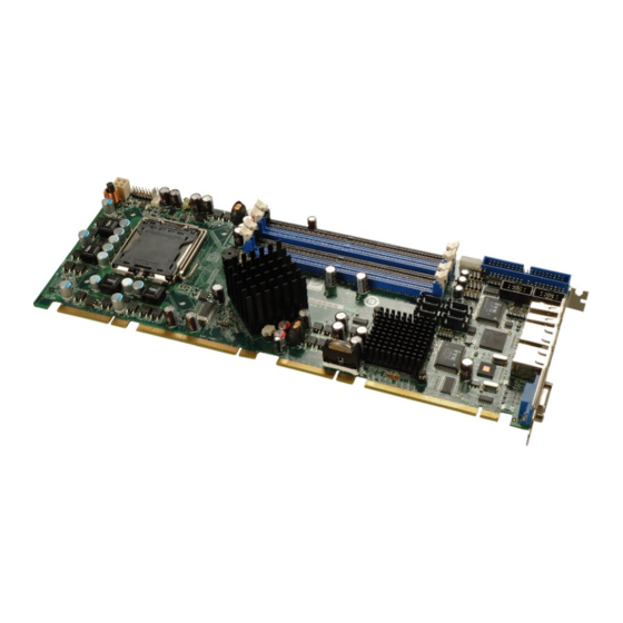
1.1 Overview Figure 1-1: 3307840 PICMG 1.3 CPU Card The 3307840 PICMG 1.3 form factor CPU card (Figure 1-1) is an LGA775 Intel® Core™2 Quad, Intel® Core™2 Duo or Intel® Celeron CPU processor platform. Both 45nm core (Wolfdale, Yorkfield) and 65nm core (Conroe) processors are supported. (For a full list of supported processors please refer to Section 2.3) -
Page 21: 3307840 Expansion Options
PICMG 1.3 form factor RoHS compliant Supports ATX power supplies 1.2 3307840 Overview 1.2.1 3307840 Overview Photo The 3307840 has a wide variety of peripheral interface connectors. Figure 1-2 is a labeled photo of the peripheral interface connectors on the 3307840. Page 4... -
Page 22: 3307840 Peripheral Connectors And Jumpers
3307840 PICMG 1.3 CPU Card Figure 1-2: 3307840 Overview [Front View] 1.2.2 3307840 Peripheral Connectors and Jumpers The 3307840 has the following connectors on-board: 1 x ATX power connector 1 x Audio connector 1 x Digital input/output (DIO) connector 2 x Fan connectors... -
Page 23: Technical Specifications
3307840 PICMG 1.3 CPU Card The 3307840 has the following external peripheral interface connectors on the board rear panel. 2 x RJ-45 Ethernet connectors 2 x USB 2.0 connectors 1 x VGA connector The 3307840 has the following on-board jumpers: Clear CMOS 1.2.3 Technical Specifications... - Page 24 3307840 PICMG 1.3 CPU Card 10-pin header 7.1 channel HD audio kit with RealTek ALC883 Audio codec and dual audio streams supported One Intel® 82566DM (PHY) and Intel® ICH9DO (MAC) One PCIe x1 Intel® 82573L (MAC and PHY) Two RS-232 serial ports through onboard pin-headers Twelve USB 2.0 devices supported:...
-
Page 25: Table 1-1: Technical Specifications
3307840 PICMG 1.3 CPU Card Three pin system fan pin-header Fan Connector Four pin CPU fan pin-header Buzzer 3.3V@3A, 5V@5.1A, +12V@4.23A and 5VSB@0.28A (2.66 GHz E6700 Intel® Core™2 Duo CPU with a 1066MHz Power Consumption FSB and four 2.0 GB, 667 MHz DDR2 DIMM running 2Dmark®... - Page 26 3307840 PICMG 1.3 CPU Card THIS PAGE IS INTENTIONALLY LEFT BLANK Page 9...
-
Page 27: Detailed Specifications
3307840 PICMG 1.3 CPU Card Chapter Detailed Specifications Page 10... -
Page 28: Dimensions
3307840 PICMG 1.3 CPU Card 2.1 Dimensions 2.1.1 Board Dimensions The dimensions of the board are listed below: Length: 338.58mm Width: 126.39mm Figure 2-1: 3307840 Dimensions (mm) 2.1.2 External Interface Panel Dimensions External peripheral interface connector panel dimensions are shown in Figure 2-2. -
Page 29: Data Flow
3307840 PICMG 1.3 CPU Card 2.2 Data Flow Figure 2-3 shows the data flow between the two on-board chipsets and other components installed on the motherboard and described in the following sections of this chapter. Figure 2-3: Data Flow Block Diagram... -
Page 30: Compatible Processors
3307840 PICMG 1.3 CPU Card 2.3 Compatible Processors 2.3.1 Supported Processors Overview The 3307840 supports the following Intel® LGA775 processors Intel® Core™2 Quad (Yorkfield) Intel® Core™2 Duo (Wolfdale) Intel® Core™2 Duo (Conroe-2M) Intel® Celeron (Conroe L) 2.3.2 Supported Intel® Core™2 Quad (Yorkfield) Processors The Yorkfield core Intel®... -
Page 31: Supported Intel® Core™2 Duo (Wolfdale) Processors
Intel® directly. 2.3.4 Supported Intel® Core™2 Duo (Conroe-2M) Processors Table 2-1 lists the Conroe-2M core Intel® Core™2 Duo processors supported on the 3307840. All the processors in Table 2-1 are 65nm LGA775 processors with the following features: Enhanced Halt State (C1E) Enhance Intel®... -
Page 32: Supported Intel® Celeron (Conroe L) Processors
Table 2-1: Supported Intel® Core™2 Duo (Conroe) Processors 2.3.5 Supported Intel® Celeron (Conroe L) Processors Table 2-1 lists the Conroe L core Intel® Celeron processors supported on the 3307840. All the processors in Table 2-1 are 65nm LGA775 processors with the following features:... -
Page 33: Intel® Q35 Memory Controller
The memory controller on the Intel® Q35 Northbridge can support up to 8.0 GB of DDR2 SDRAM. Four DDR2 SDRAM DIMM sockets on the 3307840 are interfaced to the Intel® Q35 Northbridge memory controller. The DDR2 sockets are shown in Figure 2-5. -
Page 34: Intel® Q35 Pcie X16 Interface
3307840 PICMG 1.3 CPU Card CAUTION: If more than one DDR2 DIMM is being installed in the system, please purchase two DIMM that have the same capacity and operating frequency. Each DIMM socket can support DIMMs with the following specifications:... -
Page 35: Intel® Q35 Graphics And Display Features
PCIe ports on the Intel® Q35. The SDVO interface provides 1.0 MHz point-to-point connectivity between the Intel® 35 and an SDVO device. The 3307840 provides support for a single SDVO device on a compatible GLOBAL AMERICAN backplane. The SDVO... -
Page 36: Intel® Q35 Analog Display Capabilities
3307840 PICMG 1.3 CPU Card Figure 2-6: SDVO Connector Some of the capabilities of the Intel® Q35 SDVO port are listed below: Multiplexed with the PCIe x16 graphics port signals Drives pixel clocks up to 270 MHz Supports a single-channel SDVO device. -
Page 37: Intel® Q35 Direct Media Interface (Dmi)
3307840 PICMG 1.3 CPU Card Figure 2-7: VGA Connector Some of the capabilities of the Intel® Q35 analog CRT port are listed below: 400 MHz Integrated 24-bit RAMDAC Up to 2048x1536 @ 75 Hz refresh Hardware Color Cursor Support DDC2B Compliant Interface 2.4.7 Intel®... -
Page 38: Intel ® Ich9Do Southbridge Chipset
3307840 PICMG 1.3 CPU Card Figure 2-8: DMI Chip-to-Chip Connection Some of the features of the DMI include: 2.0 GBps point-to-point DMI to ICH9DO (1.0 GBps in each direction) 100 MHz reference clock (shared with PCI Express* Graphics Attach) 32-bit downstream addressing... -
Page 39: Intel ® Ich9Do Features
3307840 PICMG 1.3 CPU Card ® 2.5.2 Intel ICH9DO Features The ICH9DO Southbridge chipset on the 3307840 has the features listed below. Complies with PCI Express Base Specification, Revision 11 Complies with PCI Local Bus Specification, Revision 2.3 and supports 33MHz PCI operations... -
Page 40: Figure 2-9: Audio Connector
A RealTek ALC883 7.1+2 channel High Definition Audio (HDA) codec on an optional GLOBAL AMERICAN® 1007760 audio kit is connected to a 10-pin onboard audio connector that is interfaced through the Intel® High Definition Audio serial link to the HDA controller integrated on the Intel®... -
Page 41: Intel ® Ich9Do Ethernet Controller
3307840 PICMG 1.3 CPU Card ® 2.5.4 Intel ICH9DO Ethernet Controller NOTE: Gigabit Ethernet (1000 Mbps) is only supported in S0. The Intel® ICH9DO Southbridge integrated GbE controller is interfaced to an Intel® 82566DM Gigabit LAN connect device through the Gigabit LAN Connect Interface (GLCI). -
Page 42: Intel® 82566Dm Gigabit Lan Connect Device
3307840 PICMG 1.3 CPU Card Compliance with PCI Power Management standards. ACPI register set and power down functionality supporting D0 & D3 states. Full wake-up support (APM and ACPI). Magic Packet wake-up enable with unique MAC address. Fragmented UDP checksum off load for package reassembly. -
Page 43: Intel ® Ich9Do Low Pin Count (Lpc) Interface
The bus masters interfaced to the two backplane PCI channels and the two PCI channels that come from the PCI bridge are all interfaced to the PCI edge connector on the bottom of the 3307840 as specified by the PICMG 1.3 form factor. Page 26... -
Page 44: Intel ® Ich9Do Pcie X1 Bus
3307840 PICMG 1.3 CPU Card ® 2.5.7 Intel ICH9DO PCIe x1 Bus The Intel® ICH9DO Southbridge chipset has six PCIe x1 lanes. The four PCIe lanes are interfaced through a PCIe edge connector at the bottom of the CPU card through a compatible half-size backplane to either four PCIe x1 expansion cards or one PCIe x4 expansion card on. -
Page 45: Intel ® Ich9Do Serial Peripheral Interface (Spi) Bios
The ICH9DO comprises six full/low speed USB controllers that support the standard Universal Host Controller Interface (UHCI) Revision 1.1. Each controller supports two USB devices ensuring up to twelve USB 1.1 devices can be connected to the 3307840. Page 28... -
Page 46: 3307840 Usb Implementation
USB port. 2.5.11.2 3307840 USB Implementation Only eight of the Intel® ICH9DO USB ports are implemented on the 3307840. Two USB ports (USB Port 1 and USB Port 2) are connected to two external connectors and six USB ports (USB Port 3 to USB Port 8) are connected to three 8-pin onboard pin-headers. -
Page 47: 3307840 Pcie Bus Components
2.6 3307840 PCIe Bus Components 2.6.1 PCIe Bus Overview The 3307840 has one PCIe x16 channel from the Intel® Q35 Northbridge and six PCIe x1 lanes from the Intel® ICH9DO Southbridge. The PCIe bus lanes are interfaced to the following devices. -
Page 48: Pcie X1 Expansion
Figure 2-14: PCIe x16 Edge connector 2.6.3 PCIe x1 Expansion Four of the six PCIe x1 expansion channels on the 3307840 are interfaced to four PCIe x1 connectors on a backplane through an edge connector on the bottom of the CPU card. The PCIe x1 edge connector is shown in Figure 2-15. -
Page 49: Figure 2-16: Intel® 82573L Pcie Gbe Controller
3307840 PICMG 1.3 CPU Card to the Intel® ICH9DO Southbridge through a PCIe x1 lane. The Intel® 82573L GbE controllers is shown in Figure 2-16 below. Figure 2-16: Intel® 82573L PCIe GbE Controller Some of the features of the Intel® 82573L are listed below: 2 Gbps peak bandwidth per direction PCI Express Rev 1.0a specification... -
Page 50: Pci Bus Components
PCI operations. 2.7.2 ITE IT8211 ATA Controller Chipset The 40-pin IDE connector on the 3307840 is connected to the ATA/ATAPI-6 ITE IT8211 ATA controller chipset, which is then connected to the Intel® ICH9DO Southbridge chipset. The controller and connector are shown in Figure 2-17 below. -
Page 51: Ite It8209 Pci Arbiter
One of the Intel® ICH9DO Southbridge PCI lanes is connected to an ITE IT8209 PCI arbiter. One set of SYSGNT# and SYSREQ# on the ITE IT8209 supports three PCI Masters thereby enabling the 3307840 to support an additional two PCI Masters. The ITE IT8209 PCI arbiter is shown in Figure 2-18 below. -
Page 52: Lpc Bus Components
3307840 PICMG 1.3 CPU Card connector on the 3307840 is interfaced to the PCI bus on the backplane thereby connecting the PCI backplane expansion boards to the Intel® ICH9DO Southbridge. The PCI bus edge connector is shown in Figure 2-19. -
Page 53: Super I/O Chipset
3307840 PICMG 1.3 CPU Card Figure 2-20: TPM Connector The Intel® ICH9DO Southbridge supports TPM version 1.1 and TPM version 1.2 devices for enhanced security. Three TPM are available from GLOBAL AMERICAN. The three GLOBAL AMERICAN TPM are listed below: Infineon TPM module... -
Page 54: Super I/O Lpc Interface
3307840 PICMG 1.3 CPU Card Figure 2-21: ITE IT8718F Super I/O The ITE IT8718F is an LPC interface-based Super I/O device that comes with an integrated Environment Controller. Some of the features of the iTE IT8718F chipset are listed below:... -
Page 55: Super I/O 16C550 Uarts
3307840 PICMG 1.3 CPU Card 2.8.3.2 Super I/O 16C550 UARTs The onboard Super I/O has two integrated 16C550 UARTs that can support the following: Two standard serial ports (COM1 and COM2) IrDa 1.0 and ASKIR protocols 2.8.3.3 Super I/O Enhanced Hardware Monitor The Super I/O Enhanced Hardware Monitor monitors three thermal inputs, VBAT internally, and eight voltage monitor inputs. -
Page 56: Super I/O Gpio Ports
2.8.3.6 Super I/O GPIO Ports The Super I/O has 48 programmable GPIO ports of which 16 are implemented on the 3307840. The GPIO connector has 16 programmable bits, 8-bit input and 8-bit output. 2.8.3.7 Super I/O Infrared The Super I/O has dedicated infrared (IrDA) pins that are interfaced to an IrDA connector. -
Page 57: Figure 2-22: Lan Connections
3307840 PICMG 1.3 CPU Card Figure 2-22: LAN Connections The first GbE controller, is an Intel® 82537L PCIe GbE controller and is the interface between the Intel® ICH9DO Southbridge controller and the LAN1 RJ-45 Ethernet connector. The second GbE controller is integrated on the Intel® ICH9DO Southbridge and interfaced to the LAN2 RJ-45 Ethernet LAN connector through an Intel®... -
Page 58: Environmental And Power Specifications
3307840 PICMG 1.3 CPU Card 2.10 Environmental and Power Specifications 2.10.1 System Monitoring Three thermal inputs on the 3307840 Super I/O Enhanced Hardware Monitor monitor the following temperatures: CPU Temperature System Temperature Five voltage inputs on the 3307840 Super I/O Enhanced Hardware Monitor monitors the... -
Page 59: Power Consumption
These backplanes and chassis are listed below. 2.11.2 GLOBAL AMERICAN Expansion PICMG 1.3 Backplanes The backplanes listed in Table 2-4 are compatible with the 3307840 and can be used to develop highly integrated industrial applications. All of the backplanes listed below have 24-pin ATX connector and a 4-pin ATX connector. -
Page 60: Global American Chassis
Single Table 2-4: Compatible GLOBAL AMERICAN PICMG 1.3 Backplanes 2.11.3 GLOBAL AMERICAN Chassis GLOBAL AMERICAN chassis available for 3307840 system development are listed in Table 2-5. For more information about these chassis please consult the GLOBAL AMERICAN catalog or contact your vendor, reseller or the GLOBAL AMERICAN sales team at salesinfo@globalamericaninc.com. - Page 61 3307840 PICMG 1.3 CPU Card Model Slot SBC Mounting Max Slots Backplanes 1107820 1107840 1107770 1404540 Full-size Wall 1107810 1107820 1107840 1107770 1404580 Full-size (4U) Rack 1107830 1107900 1107910 1107930 1107940 1404600 Full-size (4U) Rack 1107830 1107900 1107910 1107930 1407670...
-
Page 62: Table 2-5: Compatible Global American Chassis
3307840 PICMG 1.3 CPU Card Model Slot SBC Mounting Max Slots Backplanes 1107850 1404552 Full-size (2U) Rack 1107750 1107850 Table 2-5: Compatible GLOBAL AMERICAN Chassis Page 45... -
Page 63: Unpacking
3307840 PICMG 1.3 CPU Card Chapter Unpacking Page 46... -
Page 64: Anti-Static Precautions
When the 3307840 is unpacked, please do the following: Follow the anti-static precautions outlined in Section 3.1. Make sure the packing box is facing upwards so the 3307840 does not fall out of the box. Make sure all the components shown in Section 3.3 are present. -
Page 65: Unpacking Checklist
If some of the components listed in the checklist below are missing, please do not proceed with the installation. Contact the GLOBAL AMERICAN reseller or vendor you purchased the 3307840 from or contact a Global American sales representative directly. To contact a Global American sales representative, please send an email to salesinfo@globalamericaninc.com. - Page 66 3307840 PICMG 1.3 CPU Card Dual RS-232 cable KB/MS cable with Mini DIN KB/MS PS/2 Y-cable SATA cables SATA power cables Mini jumper Pack Quick Installation Guide Utility CD Page 49...
-
Page 67: Optional Items
3307840 PICMG 1.3 CPU Card USB cable Table 3-1: Package List Contents 3.4 Optional Items Audio kit (P/N: 1007760) 5-pin Wafer-to-PS/2 4-port USB cable CPU cooling kit (P/N: 2107695) Infineon TPM module (P/N: 1007790) Page 50... -
Page 68: Table 3-2: Package List Contents
3307840 PICMG 1.3 CPU Card Sinosun TPM module (P/N: 1007800) Winbond TPM module (P/N: 1007810) Table 3-2: Package List Contents Page 51... -
Page 69: Connector Pinouts
3307840 PICMG 1.3 CPU Card Chapter Connector Pinouts Page 52... -
Page 70: Peripheral Interface Connectors
Figure 4-1 shows the on-board peripheral connectors, rear panel peripheral connectors and on-board jumpers. Figure 4-1: Connector and Jumper Locations 4.1.2 Peripheral Interface Connectors Table 4-1 shows a list of the peripheral interface connectors on the 3307840. Detailed descriptions of these connectors can be found below. Connector Type... -
Page 71: External Interface Panel Connectors
USB connectors 8-pin header USB3 Table 4-1: Peripheral Interface Connectors 4.1.3 External Interface Panel Connectors Table 4-2 lists the rear panel connectors on the 3307840. Detailed descriptions of these connectors can be found in Section 4.3 on page 76. Page 54... -
Page 72: Internal Peripheral Connectors
4.2 Internal Peripheral Connectors Internal peripheral connectors are found on the motherboard and are only accessible when the motherboard is outside of the chassis. This section has complete descriptions of all the internal, peripheral connectors on the 3307840. 4.2.1 ATX Power Connector CPU12V1... -
Page 73: Figure 4-2: Atx Power Connector Location
3307840 PICMG 1.3 CPU Card Figure 4-2: ATX Power Connector Location PIN NO. DESCRIPTION +12V +12V Table 4-3: AT Power Connector Pinouts Page 56... -
Page 74: Audio Connector
CN Pinouts: See Table 4-4 NOTE: The GLOBAL AMERICAN® 1007760 audio kit is optional. If a Global American® 1007760 audio kit is required please contact the vendor or reseller the 3307840 was purchased from or contact and GLOBAL AMERICAN® sales representative directly by sending an email to salesinfo@globalamericaninc.com. -
Page 75: Digital Input/Output (Dio) Connector
3307840 PICMG 1.3 CPU Card Figure 4-3: Audio Connector Location (9-pin) PIN NO. DESCRIPTION PIN NO. DESCRIPTION SYNC BITCLK SDOUT PCBEEP SDIN RST# +12V Table 4-4: Audio Connector Pinouts 4.2.3 Digital Input/Output (DIO) Connector DIO1 CN Label: 18-pin header (2x9) -
Page 76: Figure 4-4: Dio Connector Connector Locations
3307840 PICMG 1.3 CPU Card See Figure 4-4 CN Location: CN Pinouts: See Table 4-5 The digital input/output connector is managed through a Super I/O chip. The DIO connector pins are user programmable. To see details on how to program the DIO chip, please refer to Appendix A. -
Page 77: Fan Connector, Cpu (12V, 4-Pin)
3307840 PICMG 1.3 CPU Card PIN NO. DESCRIPTION PIN NO. DESCRIPTION Input 0 Output 0 Input 1 Output 1 Input 2 Output 2 Input 3 Output 3 Input 4 Output 4 Input 5 Output 5 Input 6 Output 6 Input 7... -
Page 78: Figure 4-5: +12V Fan Connector Location
3307840 PICMG 1.3 CPU Card Figure 4-5: +12V Fan Connector Location PIN NO. DESCRIPTION +12VCC Rotation Signal Control Table 4-6: +12V Fan Connector Pinouts Page 61... -
Page 79: Fan Connector, System (+12V)
3307840 PICMG 1.3 CPU Card 4.2.5 Fan Connector, System (+12V) CN Label: SYS_FAN1 3-pin header CN Type: See Figure 4-6 CN Location: CN Pinouts: See Table 4-7 The system cooling fan connector provides a 12V, 500mA current to a system cooling fan.. -
Page 80: Front Panel Connector (14-Pin)
3307840 PICMG 1.3 CPU Card PIN NO. DESCRIPTION +12V Rotation Signal Table 4-7: +12V Fan Connector Pinouts 4.2.6 Front Panel Connector (14-pin) CN Label: F_PANEL1 CN Type: 12-pin header (2x6) CN Location: See Figure 4-7 CN Pinouts: See Table 4-8 The front panel connector connects to external switches and indicators to monitor and controls the motherboard. -
Page 81: Figure 4-7: Front Panel Connector Pinout Locations (14-Pin)
3307840 PICMG 1.3 CPU Card Figure 4-7: Front Panel Connector Pinout Locations (14-pin) FUNCTION DESCRIPTION FUNCTION DESCRIPTION Power LED LED+ Speaker SPEAKER+ LED- Power Button PWRBTSW+ SPEAKER - PWRBTSW- Reset HDD LED IDE LED+ RESET+ IDE LED- RESET- Table 4-8: Front Panel Connector Pinouts (14-pin) -
Page 82: Ide Connector (40-Pin)
CN Label: IDE1 40-pin header (2x20) CN Type: See Figure 4-8 CN Location: CN Pinouts: See Table 4-9 One 40-pin IDE device connector on the 3307840 supports connectivity to two hard disk drives. Figure 4-8: IDE Device Connector Locations Page 65... -
Page 83: Infrared Interface Connector (5-Pin)
3307840 PICMG 1.3 CPU Card PIN NO. DESCRIPTION PIN NO. DESCRIPTION RESET# GROUND DATA 7 DATA 8 DATA 6 DATA 9 DATA 5 DATA 10 DATA 4 DATA 11 DATA 3 DATA 12 DATA 2 DATA 13 DATA 1 DATA 14... -
Page 84: Keyboard/Mouse Connector
3307840 PICMG 1.3 CPU Card Figure 4-9: Infrared Connector Pinout Locations PIN NO. DESCRIPTION IR-RX IR-TX Table 4-10: Infrared Connector Pinouts 4.2.9 Keyboard/Mouse Connector CN Label: CN22 CN Type: 6-pin header (1x6) Page 67... -
Page 85: Figure 4-10: Keyboard/Mouse Connector Location
3307840 PICMG 1.3 CPU Card See Figure 4-10 CN Location: CN Pinouts: See Table 4-11 The keyboard and mouse connector can be connected to a standard PS/2 cable or PS/2 Y-cable to add keyboard and mouse functionality to the system. -
Page 86: Sata Drive Connectors
3307840 PICMG 1.3 CPU Card PIN NO. DESCRIPTION +5V KB DATA MS DATA MS CLK KB DATA KB CLK GROUND Table 4-11: Keyboard/Mouse Connector Pinouts 4.2.10 SATA Drive Connectors SATA1, SATA2, SATA3, SATA4, SATA5. and SATA6 CN Label: CN Type:... -
Page 87: Figure 4-11: Sata Drive Connector Locations
3307840 PICMG 1.3 CPU Card Figure 4-11: SATA Drive Connector Locations PIN NO. DESCRIPTION Table 4-12: SATA Drive Connector Pinouts Page 70... -
Page 88: Serial Port Connector (Com1, Com 2)
3307840 PICMG 1.3 CPU Card 4.2.11 Serial Port Connector (COM1, COM 2) COM1 and COM2 CN Label: CN Type: 10-pin header (2x5) CN Location: See Figure 4-12 CN Pinouts: See Table 4-13 The 10-pin serial port connector provides a second RS-232 serial communications channel. -
Page 89: Trusted Platform Module (Tpm) Connector
3307840 PICMG 1.3 CPU Card PIN NO. DESCRIPTION PIN NO. DESCRIPTION Data Carrier Direct (DCD) Data Set Ready (DSR) Receive Data (RXD) Request To Send (RTS) Transmit Data (TXD) Clear To Send (CTS) Data Terminal Ready (DTR) Ring Indicator (RI) -
Page 90: Figure 4-13: Tpm Connector Pinout Locations
3307840 PICMG 1.3 CPU Card Figure 4-13: TPM Connector Pinout Locations PIN NO. DESCRIPTION PIN NO. DESCRIPTION LCLK GND2 LFRAME# LRESET# LAD3 LAD2 LAD1 LAD0 GND3 SB3V SERIRQ Page 73... -
Page 91: Sdvo Control Connector
If an SDVO graphics card is installed on the PCIe x16 expansion slot on the backplane, the 1x3 pin Serial Digital Video Output (SDVO) control connector must be connected to a corresponding SDVO control connector on a compatible GLOBAL AMERICAN backplane. Figure 4-14:SDVO Connector Pinout Locations... -
Page 92: Usb Connectors (Internal)
3307840 PICMG 1.3 CPU Card PIN NO. DESCRIPTION EXP_EN SDVO_CLOCK SDVO_DATA Table 4-15: SDVO Connector Pinouts 4.2.14 USB Connectors (Internal) CN Label: USB1, USB2 and USB3 CN Type: 8-pin header (2x4) CN Location: See Figure 4-15 CN Pinouts: See Table 4-16 The 2x4 USB pin connectors each provide connectivity to two USB 1.1 or two USB 2.0... -
Page 93: External Peripheral Interface Connector Panel
DATAM+ DATAN+ DATAM- Table 4-16: USB Port Connector Pinouts 4.3 External Peripheral Interface Connector Panel Figure 4-16 shows the 3307840 external peripheral interface connector (EPIC) panel. The 3307840 EPIC panel consists of the following: 1 x DVI connector Page 76... -
Page 94: Lan Connectors
CN Pinouts: See Table 4-17 The 3307840 is equipped with two built-in RJ-45 Ethernet controllers. The controllers can connect to the LAN through two RJ-45 LAN connectors. There are two LEDs on the connector indicating the status of LAN. The pin assignments are listed in the following... -
Page 95: Usb Connector
CN Label: USB_1 and USB_2 CN Type: USB port CN Location: See Figure 4-16 CN Pinouts: See Table 4-19 The 3307840 has four external USB 2.0 ports. The ports connect to both USB 2.0 and USB 1.1 devices. Page 78... -
Page 96: Vga Connector
VGA1 15-pin Female CN Type: CN Location: See Figure 4-16 CN Pinouts: See Figure 4-18 and Table 4-20 The 3307840 has a single 15-pin female connector for connectivity to standard display devices. Figure 4-18: VGA Connector DESCRIPTION DESCRIPTION GREEN BLUE... -
Page 97: Table 4-20: Vga Connector Pinouts
3307840 PICMG 1.3 CPU Card DESCRIPTION DESCRIPTION HSYNC VSYNC DDCCLK Table 4-20: VGA Connector Pinouts Page 80... - Page 98 3307840 PICMG 1.3 CPU Card THIS PAGE IS INTENTIONALLY LEFT BLANK Page 81...
-
Page 99: Installation
3307840 PICMG 1.3 CPU Card Chapter Installation Page 82... -
Page 100: Anti-Static Precautions
Electrostatic discharge (ESD) can cause serious damage to electronic components, including the 3307840. Dry climates are especially susceptible to ESD. It is therefore critical that whenever the 3307840, or any other electrical component is handled, the following anti-static precautions are strictly adhered to. -
Page 101: Installation Considerations
NOTE: The following installation notices and installation considerations should be read and understood before the 3307840 is installed. All installation notices pertaining to the installation of the 3307840 should be strictly adhered to. Failing to adhere to these precautions may lead to severe damage of the 3307840 and injury to the person installing the motherboard. -
Page 102: Installation Checklist
3307840 PICMG 1.3 CPU Card When working with the 3307840, make sure that it is disconnected from all power supplies and that no electricity is being fed into the system. Before and during the installation of the 3307840 DO NOT: Remove any of the stickers on the PCB board. -
Page 103: Unpacking
When the 3307840 is unpacked, please do the following: Follow the anti-static precautions outlined in Section 5.1. Make sure the packing box is facing upwards so the 3307840 does not fall out of the box. Make sure all the components in the checklist shown in Chapter 3 are present. -
Page 104: Socket Lga775 Cpu Installation
3307840 PICMG 1.3 CPU Card The CPU, CPU cooling kit and DIMM are the most critical components of the 3307840. If one of these components is not installed the 3307840 cannot run. 5.4.1 Socket LGA775 CPU Installation NOTE: Enabling Hyper-Threading Technology on your system requires meeting all of the platform requirements listed below: CPU: An Intel®... -
Page 105: Figure 5-1: Intel® Lga775 Socket
3307840 PICMG 1.3 CPU Card Figure 5-1: Intel® LGA775 Socket To install a socket LGA775 CPU onto the 3307840, follow the steps below: WARNING: When handling the CPU, only hold it on the sides. DO NOT touch the pins at the bottom of the CPU. -
Page 106: Figure 5-3: Open The Cpu Socket Load Plate
3307840 PICMG 1.3 CPU Card position. Then rotate the load plate towards the opposite direction. See Figure 5-3. Figure 5-3: Open the CPU Socket Load Plate Step 3: Inspect the CPU socket Make sure there are no bent pins and make sure the socket contacts are free of foreign material. -
Page 107: Socket Lga775 2107695 Cooling Kit Installation
WARNING: It is strongly recommended that you DO NOT use the original heat sink and cooler provided by Intel® on the 3307840. GLOBAL AMERICAN’s cooling kit (2107695) includes a support bracket that is combined with the heat sink mounted on the CPU to counterweigh and balance the load on both sides of the PCB. -
Page 108: Figure 5-5: Global American 2107695 Cooling Kit
3307840 PICMG 1.3 CPU Card Figure 5-5: GLOBAL AMERICAN 2107695 Cooling Kit A Global American Socket LGA775 CPU cooling kit shown in Figure 5-5 can be purchased separately. The cooling kit comprises a CPU heat sink and a cooling fan. -
Page 109: Dimm Installation
Step 6: Connect the fan cable. Connect the cooling kit fan cable to the fan connector on the 3307840. Carefully route the cable and avoid heat generating chips and fan blades. Step 0: 5.4.3 DIMM Installation... -
Page 110: Dimm Purchasing Guidelines
3307840 PICMG 1.3 CPU Card 5.4.3.1 DIMM Purchasing Guidelines WARNING: Only use DDR2 DIMMs. If DDR DIMMs are used the system may be irreparably damaged. When purchasing the DDR2 DIMM, please follow the guidelines below: ONLY purchase DDR2 DIMM Have a frequency of 667 MHz or 800 MHz Have a maximum capacity of 2.0 GB... -
Page 111: Dimm Installation Guidelines
3307840 PICMG 1.3 CPU Card On the 3307840, each channel is interfaced to two 240-pin DIMM sockets in the following order (see Figure 5-7 above): Channel A: DIMM1 and DIMM2 Channel B: DIMM3 and DIMM4 When populating the DDR2 DIMM sockets, populate them in the following order to optimize... -
Page 112: Jumper Settings
3307840 PICMG 1.3 CPU Card Figure 5-8: Installing a DIMM Step 3: Insert the DIMM. Once properly aligned, the DIMM can be inserted into the socket. As the DIMM is inserted, the white handles on the side of the socket will close automatically and secure the DIMM to the socket. -
Page 113: Clear Cmos Jumper
3307840 PICMG 1.3 CPU Card Before the 3307840 is installed in the system, the jumpers must be set in accordance with the desired configuration. The jumpers on the 3307840 are listed in Table 5-1. Description Label Type Clear CMOS J_CMOS1... -
Page 114: Figure 5-9: Clear Cmos Jumper
3307840 PICMG 1.3 CPU Card Jumper Select Description Short 1 - 2 Keep CMOS Setup Default Short 2 - 3 Clear CMOS Setup Table 5-2: Clear CMOS Jumper Settings The location of the clear CMOS jumper is shown in Figure 5-9 below. -
Page 115: Chassis Installation
The 3307840 must be installed in a chassis with ventilation holes on the sides allowing airflow to travel through the heat sink surface. In a system with an individual power supply unit, the cooling fan of a power supply can also help generate airflow through the board surface. -
Page 116: Cpu Card Installation
5.6.3 CPU Card Installation To install the 3307840 CPU card onto the backplane, carefully align the CPU card interface connectors with the corresponding socket on the backplane. To do this, please refer to the reference material that came with the backplane. -
Page 117: Ata Flat Cable Connection
5.7.2 ATA Flat Cable Connection The ATA 66/100 flat cable connects to the 3307840 to one or two IDE devices. To connect an IDE HDD to the 3307840 please follow the instructions below. -
Page 118: Audio Kit Installation
An optional audio kit that is separately ordered connects to the 9-pin audio connector on the 3307840. The audio kit consists of five audio jacks. One audio jack, Mic In, connects to a microphone. The remaining four audio jacks, Front-In, Front-Out, Rear-Out and subwoofer connect to four speakers including a subwoofer. -
Page 119: Dual Rs-232 Cable Connection
3307840 PICMG 1.3 CPU Card Step 2: Align pin 1. Align pin 1 on the onboard connector with pin 1 on the audio kit connector. Pin 1 on the audio kit connector is indicated with a white dot. See Figure 5-11. -
Page 120: Sata Drive Connection
0: 5.7.5 SATA Drive Connection The 3307840 is shipped with two SATA drive cables and one SATA drive power cable. To connect the SATA drives to the connectors, please follow the steps below. Step 1: Locate the connectors. -
Page 121: Figure 5-13: Sata Drive Cable Connection
3307840 PICMG 1.3 CPU Card Step 2: Insert the cable connector. Press the clip on the connector at the end of the SATA cable and insert the cable connector into the onboard SATA drive connector. See Figure 5-13. Figure 5-13: SATA Drive Cable Connection Step 3: Connect the cable to the SATA disk. -
Page 122: Usb Cable (Dual Port)
3307840 PICMG 1.3 CPU Card Figure 5-14: SATA Power Drive Connection 5.7.6 USB Cable (Dual Port) The 3307840 is shipped with a dual port USB 2.0 cable. To connect the USB cable connector, please follow the steps below. Step 1: Locate the connectors. -
Page 123: Installing Devices On Apicmg 1.3 Backplane
PCIe x4 expansion cards PCIe x1 expansion cards PCI expansion cards 5.8.1 SDVO Device Installation To install an SDVO device on the backplane, please follow the steps below: Step 1: Make sure the 3307840 is properly installed on the backplane Page 106... -
Page 124: External Peripheral Interface Connection
USB device cable connectors VGA device cable connectors To install these devices, connect the corresponding cable connector from the actual device to the corresponding 3307840 external peripheral interface connector making sure the pins are properly aligned. 5.9.1 LAN Connection (Single Connector) There are two external RJ-45 LAN connectors. -
Page 125: Ps/2 Y-Cable Connection
3307840 PICMG 1.3 CPU Card Figure 5-16: LAN Connection Step 7: Insert the LAN cable RJ-45 connector. Once aligned, gently insert the LAN cable RJ-45 connector into the onboard RJ-45 connector. Step 0: 5.9.2 PS/2 Y-Cable Connection NOTE: Before installing the PS/2 Y-cable connector, make sure the keyboard... -
Page 126: Usb Device Connection (Single Connector)
The 3307840 has a PS/2 connector on the external peripheral interface panel. The dual PS/2 connector is connected to the PS/2 Y-cable that came with the 3307840. One of the PS/2 cables is connected to a keyboard and the other to a mouse to the system. Follow the steps below to connect a keyboard and mouse to the 3307840. -
Page 127: Vga Monitor Connection
Step 0: 5.9.4 VGA Monitor Connection The 3307840 has a single female DB-15 connector on the external peripheral interface panel. The DB-15 connector is connected to a CRT or VGA monitor. To connect a monitor to the 3307840, please follow the instructions below. - Page 128 3307840 PICMG 1.3 CPU Card Step 3: Insert the VGA connector. Once the connectors are properly aligned with the insert the male connector from the VGA screen into the female connector on the 3307840. See Figure 5-19. Figure 5-19: VGA Connector Step 4: Secure the connector.
- Page 129 3307840 PICMG 1.3 CPU Card THIS PAGE IS INTENTIONALLY LEFT BLANK Page 112...
- Page 130 3307840 PICMG 1.3 CPU Card Page 113...
-
Page 131: Adio Interface
3307840 PICMG 1.3 CPU Card Appendix DIO Interface Page 114... -
Page 132: Dio Connector Pinouts
3307840 PICMG 1.3 CPU Card A.1 DIO Interface Introduction The DIO connector on the 3307840 is interfaced to GIO ports on the iTE Super I/O chipset. The DIO has both 8-bit digital inputs and 8-bit digital outputs. The digital inputs and digital outputs are generally control signals that control the on/off circuit of external devices or TTL devices. -
Page 133: Assembly Language Samples
3307840 PICMG 1.3 CPU Card Output 7 20 (GP27) General purpose I/O port 2 bit 7 A.3 Assembly Language Samples A.3.1 Enable the DIO Input Function The BIOS interrupt call INT 15H controls the digital I/O. An assembly program to enable digital I/O input functions is listed below. - Page 134 3307840 PICMG 1.3 CPU Card THIS PAGE IS INTENTIONALLY LEFT BLANK Page 117...
-
Page 135: Bwatchdog Timer
3307840 PICMG 1.3 CPU Card Appendix Watchdog Timer Page 118... - Page 136 NOTE: The following discussion applies to DOS environment. GLOBAL AMERICAN support is contacted or the GLOBAL AMERICAN website visited for specific drivers for more sophisticated operating systems, e.g., Windows and Linux. The Watchdog Timer is provided to ensure that standalone systems can always recover from catastrophic conditions that cause the CPU to crash.
- Page 137 3307840 PICMG 1.3 CPU Card Page 120...
- Page 138 3307840 PICMG 1.3 CPU Card NOTE: When exiting a program it is necessary to disable the Watchdog Timer, otherwise the system resets. Example program: ; INITIAL TIMER PERIOD COUNTER W_LOOP: AX, 6F02H ;setting the time-out value BL, 30 ;time-out value is 48 seconds ;...
- Page 139 3307840 PICMG 1.3 CPU Card THIS PAGE IS INTENTIONALLY LEFT BLANK Page 122...
-
Page 140: Caddress Mapping
3307840 PICMG 1.3 CPU Card Appendix Address Mapping Page 123... -
Page 141: Address Map
3307840 PICMG 1.3 CPU Card C.1 Address Map I/O address Range Description 000-01F DMA Controller 020-021 Interrupt Controller 040-043 System time 060-06F Keyboard Controller 070-07F System CMOS/Real time Clock 080-09F DMA Controller 0A0-0A1 Interrupt Controller 0C0-0DF DMA Controller 0F0-0FF Numeric data processor... -
Page 142: Irq Mapping Table
3307840 PICMG 1.3 CPU Card C.3 IRQ Mapping Table IRQ0 System Timer IRQ8 RTC clock IRQ1 Keyboard IRQ9 ACPI IRQ2 Available IRQ10 IRQ3 COM2 IRQ11 LAN/USB2.0/SATA IRQ4 COM1 IRQ12 PS/2 mouse IRQ5 SMBus Controller IRQ13 IRQ6 IRQ14 Primary IDE IRQ7... - Page 143 3307840 PICMG 1.3 CPU Card THIS PAGE IS INTENTIONALLY LEFT BLANK Page 126...
-
Page 144: Dintel
3307840 PICMG 1.3 CPU Card Appendix ® Intel Matrix Storage Manager Page 127... -
Page 145: Introduction
3307840 PICMG 1.3 CPU Card D.1 Introduction The Intel® ICH9DO chipset can provide data protection for serial ATA (SATA) disks via the Intel® Matrix Storage Manager using one of three fault-tolerant RAID levels: RAID 1, 5 or 10. When using two hard drives, matrix RAID allows RAID 0 and RAID 1 functions to be combined, where critical files can be stored on RAID 1, and RAID 0 can be used for non-critical items such as software. -
Page 146: Features And Benefits
3307840 PICMG 1.3 CPU Card CAUTION! Do not accidentally disconnect the SATA drive cables. Carefully route the cables within the chassis to avoid system down time. D.2 Features and Benefits Supports RAID levels 0, 1, 5 and 10 Supports connectivity to two or more disk drives... -
Page 147: Raid Configuration
3307840 PICMG 1.3 CPU Card Step 3: Save and Exit BIOS. After the SATA support option is enabled, save and exit the BIOS. Step 4: Reboot the system. Reboot the system after saving and exiting the BIOS. Step 5: Press Ctrl+I. During the system boot process, press Ctrl+I when prompted to enter the RAID configuration software. - Page 148 3307840 PICMG 1.3 CPU Card Figure D-1: Matrix Storage Manager Main Menu Step 2: Name the RAID volume. Enter a name for the RAID volume, or press E NTER accept the default volume name. Upper and lower case alphabetic, numeric, space, and underscore characters are all applicable for naming an array.
- Page 149 3307840 PICMG 1.3 CPU Card NOTE: RAID 0 and RAID1 levels require a minimum of two hard drives. RAID 10 level requires a minimum of four hard drives. RAID5 level requires a minimum of three hard drives. Figure D-3: Choose the Raid Level Step 4: Select the Stripe Size.
- Page 150 3307840 PICMG 1.3 CPU Card Figure D-4: Select the Stripe Size Step 5: Enter the Volume Capacity. Enter the volume capacity, or press E NTER accept the default capacity. See Figure D-5. Figure D-5: Enter the Volume Capacity Step 6: Create the RAID Volume.
- Page 151 3307840 PICMG 1.3 CPU Card Figure D-6: Create the RAID Volume Step 7: Create RAID Volume Verification. After reading the warning, press Y to create the RAID volume as specified, or N to return to the Create RAID Volume menu.
-
Page 152: Deleting A Raid Volume
3307840 PICMG 1.3 CPU Card D.4.2 Deleting a RAID Volume WARNING! All data stored on the member drives of a RAID volume are destroyed during the RAID deletion process. Make sure any data to be saved has been moved or backed up before deleting a RAID volume. - Page 153 3307840 PICMG 1.3 CPU Card Step 2: Select RAID Volume to be Deleted. Use the arrow keys to highlight the RAID volume to be deleted and press E . See Figure D-9. NTER Figure D-9: Select RAID Volume to be Deleted Step 3: Delete Volume Verification.
-
Page 154: Resetting A Disk To Non-Raid
3307840 PICMG 1.3 CPU Card Figure D-11: Non-RAID Disks D.4.3 Resetting a Disk to Non-RAID WARNING! All data stored on the disk drive of a RAID volume is destroyed when resetting it to non-RAID. Make sure any data to be saved has been moved or backed up before resetting a disk to non-RAID. - Page 155 3307840 PICMG 1.3 CPU Card Figure D-12: Reset Disk to Non-RAID Menu Step 2: Select Disks to Reset. Use the arrow keys to scroll through the disk drives and press S to select which drives are to be reset as non-RAID. After all the...
-
Page 156: Exiting The Matrix Storage Manager
3307840 PICMG 1.3 CPU Card Figure D-14: Reset Disk Verification Step 4: Disk Drive and RAID Volume Status. After the disk drives have been reset, the Matrix Storage Manager Main menu is shown indicating the status of the RAID volumes and disk drives. See Figure D-15. - Page 157 3307840 PICMG 1.3 CPU Card Figure D-16: Exit Menu Step 2: Exit Verification. Press Y to exit the Matrix Storage Manager, or N to return to the Main menu. See Figure D-17. Step 0: Figure D-17: Exit Verification Page 140...
-
Page 158: Ehazardous Materials Disclosure
3307840 PICMG 1.3 CPU Card Appendix Hazardous Materials Disclosure Page 141... - Page 159 3307840 PICMG 1.3 CPU Card E.1 Hazardous Material Disclosure Table for IPB Products Certified as RoHS Compliant Under 2002/95/EC Without Mercury The details provided in this appendix are to ensure that the product is compliant with the Peoples Republic of China (China) RoHS standards. The table below acknowledges the presences of small quantities of certain materials in the product, and is applicable to China RoHS only.
- Page 160 3307840 PICMG 1.3 CPU Card Part Name Toxic or Hazardous Substances and Elements Lead Mercury Cadmium Hexavalent Polybrominated Polybrominated (Pb) (Hg) (Cd) Chromium Biphenyls Diphenyl Ethers (CR(VI)) (PBB) (PBDE) Housing Display Printed Circuit Board Metal Fasteners Cable Assembly Fan Assembly...
- Page 161 3307840 PICMG 1.3 CPU Card Index Page 144...
- Page 162 3307840 PICMG 1.3 CPU Card backplane installation...... 98 installation........98 chipset ..........22 airflow ..........98 southbridge........22 anti-static precautions ....47, 83 clear CMOS jumper ......6, 96 anti-static pad ......47, 83 location..........97 anti-static wristband ....47, 83 settings ..........
- Page 163 3307840 PICMG 1.3 CPU Card cooling fan ........91 connectors ........106 heat sink .......... 91 external switches......... 63 installation........87 CPU card..........99 installation........99 fan connector........62 CPU cooling fan........60 location and pinouts ......62 CPU fan connector......60 fan connector........
- Page 164 3307840 PICMG 1.3 CPU Card location and pinouts ......66 PS/2 cable ........... 68 installation checklist......85 PS/2 keyboard and mouse connection ........108 jumper ........... 95, 96 clear CMOS ........96 RAID........... 69 jumper configuration....... 96 real time clock........27 jumper settings ........
- Page 165 3307840 PICMG 1.3 CPU Card location and pinouts ......71 connectors ........105 serial ports........... 38 devices ..........75 SIR interface ........66 external USB device connection... 109 socket LGA775 CPU port ..........75 cooling kit ........90 USB 1.1........... 75 cooling kit installation.....
- Page 166 Any advice or comments about our products and service, or anything we can help you with please don’t hesitate to contact with us. We will do our best to support your products, projects and business. Address: Global American, Inc. 17 Hampshire Drive Hudson, NH 03051 Telephone: Toll Free (U.S. Only) 800-833-8999...
Need help?
Do you have a question about the 3307840 and is the answer not in the manual?
Questions and answers