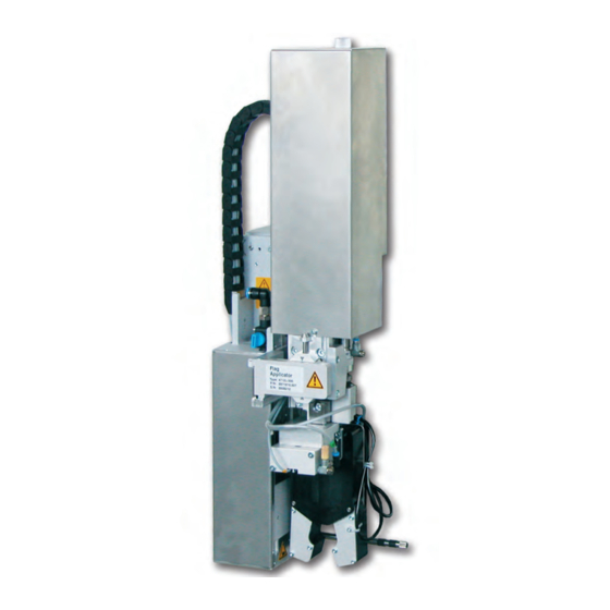
CAB 4712 Service Manual
Flag applicator
Hide thumbs
Also See for 4712:
- Service manual (53 pages) ,
- Assembly instructions manual (30 pages) ,
- Operator's manual (13 pages)
Table of Contents
Advertisement
Quick Links
Advertisement
Table of Contents

Related Manuals for CAB 4712


Summary of Contents for CAB 4712
- Page 1 Service Manual Flag Applicator 4712 Made in Germany...
- Page 2 Edition: 07/2019 - Part No. 9009954 Copyright This documentation as well as translation hereof are property of cab Produkttechnik GmbH & Co. KG. The replication, conversion, duplication or divulgement of the whole manual or parts of it for other intentions than its original intended purpose demand the previous written authorization by cab.
-
Page 3: Table Of Contents
Tamp Assembly up to SN: 12652 ......................38 Tamp Assembly from SN: 12653 ......................39 Illustrations ............................40 10.1 Block Diagram ............................40 10.2 Pneumatic Illustration Type 4712 up to SN: 12652 ................41 10.3 Pneumatic Illustration Type 4712 from SN: 12653 ................42 Index ..............................43... -
Page 4: Introduction
• The device applicator mounted on a cab printer of the Hermes+ series is intended exclusively for applying suitable materials that have been approved by the manufacturer. Any other use or use going beyond this shall be regarded as improper use. -
Page 5: Safety Markings
Introduction • Before mounting the delivered components disconnect the printer from the power supply and close the shutoff valve of the applicator. • Only connect the device to other devices which have a protective low voltage. • Switch off all affected devices (computer, printer, accessories) before connecting or disconnecting. •... -
Page 6: Product Description
Flag length L Flag length L α α Figure 2 Applicator parameters Form pad α Technical data 4712 L 300 α Label width Hermes + 4 60 - 100 Label height 10 - 50 Form pad Diameter 3 - 16... -
Page 7: Product Overview Without Cover
Product Description Product Overview without Cover Front view Throttle valve vacuum/support air Figure 3 Product overview - front view 1 Throttle valve cylinder - retraction motion z-direction 9 Setting crew for the sideways stamp position 2 Stopper for blowing mode and transportation 10 Stamp group 3 Thumb screw for fixing the applicator to the printer 11 Blow tube... - Page 8 Product Description Rear view Valves and settings Figure 5 Product Overview - Control Unit Figure 4 Product overview - rear view Throttle valve cylinder - retraction motion z-direction Magnetic valve cylinder z Throttle valve cylinder - extension motion z-direction Magnetic valve cylinder lock Stamp (user defined) Magnetic valve compressed air Blow tube for pressure...
-
Page 9: Contents Of Delivery
Product Description Contents of Delivery 1 Applicator with mounted pad 2 Blow tube for supporting air (depending on the used printer) 3 Documentation Figure 6 Contents of delivery Note! Please keep the original packaging in case the applicator must be returned or transported. Attention! The device as well as the printing materials will be damaged by moisture and wetness. -
Page 10: Operation
Operation Standard Operation Check all external connections. Load the material. Ensure that the locking system is locked Operator's Manual of the printer. Open the shutoff valve of the air pressure. Attention! Ensure that the pad is not covered by a label when switching on the printer-applicator system. Otherwise the vacuum sensor may be calibrated incorrectly. - Page 11 Operation Figure 8 Mounting/demounting the applicator on/from the printer Attention! Initiation, adjustments and changing of parts is to be performed by qualified service personnel only. Service Manual Applicator Attention! Disconnect the printer from the power supply before mounting the applicator! Ensure the printer is in a stable position! Connect the compressed air only after mounting the applicator to the printer! To clean the applicator and printer it is occasionally necessary to turn away or even demount the applicator from the printer.
-
Page 12: Error Messages
Error Messages Error Messages of the Printer For detailed information about printer errors (e.g. 'Paper out', 'Ribbon out', etc.) check Operator's manual of the printer. Error treatment: Clearing the error results. Press the feed key to synchronize the label feed, remove the left over labels manually. ... -
Page 13: Installation
Note! When using the applicator for client specified jobs a custom configuration is installed. Thus the performance will be measured by the values of the commissioning certificate and not the standard values. The standard values for the default settings are as follows: - standing connection to a cab Hermes+ printer - continuous air pressure of 0,45 MPa (4,5 bar) Required Space approx. 42 mm 3 5 ° Printing direction... -
Page 14: Tools
Installation Tools Screwdriver with parallel blade To adjust the throttle valves and product sensor Hexagon key L-wrench To adjust the sensors (in contents of delivery) For matched norm parts (in contents of delivery) Pad adjustments Changing pad Flat-round nose To mount/dismount tubes straight angled Open spanner... -
Page 15: Mounting The Applicator
Installation Mounting the Applicator Attention! Disconnect the printer from the power supply before mounting/demounting the applicator! Ensure the printer is in a stable position Only when the applicator is securely mounted on the printer connect the compressed air. 1. -
Page 16: Mounting The Blow Tube
Installation Mounting the Blow Tube Figure 13 Mounting the blow tube The blow tube (3) can be rotated around its axis. By this principle the direction of the compressed air can be optimized. 1. Loosen the screw (1). 2. Insert the blow tube (3) as far as possible into the provided slot B (2). 3. -
Page 17: Adjustments
1. Loosen screws (3). 2. Use the adjusting tool (6) included (cab serial No.: 5972857) as shown in the picture to adjust the suction plates. 3. Slide each suction plate (4) over the corresponding driving pin (2) to the adjusting tool (6). -
Page 18: Adjusting The Pad
Adjustments Adjusting the Pad For the perfect application of labels it is necessary that the pad is placed precisely above the dispensed label. Aligning the pad parallel to the dispensing plate. The edge of the pad should be positioned parallel to the dispensing plate of the printer in order to position the label exactly on the pad. - Page 19 Adjustments Moving the pad in x-, y- and z-direction 1 mm Figure 19 Moving the pad assembly Adjustment in X-direction (sideways adjustment) 1. Loosen screw (3). 2. Move cylinder assembly (5) with the pad along the bearing (4) so that the dispensed label is aligned centrally to the pad.
-
Page 20: Alignment Of The Product To The Applicator
Adjustments Alignment of the Product to the Applicator Depending on the orientation of the applicator to the printer the alignment of the product will take place. Note! For optimal alignment of the product for labeling a fixed uptake of the product is necessary. Printing direction (tamp axis) 90° Edge of tamp (dispensing plate of the printer) Figure 20 Alignment of the product to the tamp The product (3, 5) must be aligned 90°... -
Page 21: Setting The Application Height
Adjustments Setting the Application height The following steps explain the labeling procedure. The label is printed, transported to the dispensing plate and taken up by the applicator. The applicator assembly group, with the two piece pad (3), drives to the application position where the stopper (5) brakes the motion of the assembly group. -
Page 22: Adjusting The Vacuum
Adjustments Adjusting the Vacuum Via the negative pressure the label is fixed to the applicator. This vacuum needs to be strong enough to hold the label and cover all suction apertures. It may not be strong enough to hinder the transport of the from the printer to the applicator. This is dependent on the label material used. The default value of the vacuum is -0.6 bar. Note! By adjusting the vacuum it is possible to prevent the label from being applied to the product. -
Page 23: Adjustments To The Blowpipe (Supporting Air)
Adjustments Adjustments to the Blowpipe (Supporting Air) For optimal support during the acquisition of the label of the applicator the supporting air is to be set up so that it is free of turbulence and evenly pushes the label against the pad. The default air pressure value is set to 2 bar. - Page 24 Adjustments Measuring point (MP S) for Supporting Air. With a Manometer that is capable of measuring pressures ranging from -7 to 7 bar the effective pressures can be measured. MP S: Support air (desired default value 2 bar) 1. Remove the cover and interpose the manometer at the MP S .
-
Page 25: Adjustment To The Speed Of Cylinder Z
Adjustments Adjustment to the Speed of Cylinder Z Figure 28 Throttle valves at cylinder z Adjustments to the speed of the up and down motion can be performed via exhaust-throttle valves (1, 3). Adjust the speed to suit the requirements. ... -
Page 26: Settings Of The Sensors Of Cylinder Z
Adjustments Settings of the Sensors of Cylinder Z Figure 29 Sensors on cylinder z Impact sensor upper end 1. Loosen screw (1) of sensor "upper position" (3) and move the sensor to lock into the sensor retainer. 2. Remove the tubes from the pressure connectors of cylinder z and switch on the printer after connecting the applicator. -
Page 27: Setting Of The End Position Dampener
Adjustments 6.10 Setting of the End Position Dampener Note! The end position dampening of the lifting cylinders are set to clients specification by default and will normally not need to be adjusted. The end position dampening of the cylinder z is for relief of mechanical strain particularly at higher speeds or when using a larger mass. The end position dampening is best set up so the piston reaches both ends securely but does not impact anything harshly. -
Page 28: Configuring The Printer
Configuring the Printer The method of use of the applicator can be modified by altering the parameter settings. The most important setting is the choice between the mode "stamp" and "blow." Besides that the applicator has different sequences of printing and applying labels in a labeling cycle. The flag applicator will activate in the mode of operation Blow pursued around all necessary parameters and to be able to modify. -
Page 29: Configuration Parameters Of The Applicator
Configuring the Printer Configuration Parameters of the Applicator The configuration parameters of the applicator can be found in the menu Setup > Machine param. Parameter Meaning Default > Applicator Configuration parameter of the applicator > Mode of oper. Setting of the mode Stamp or Blow Blow > Mode Print-apply Selection of the type of cyclic operation: Print-apply The start signal prints a label and applies it to a product. After the cycle the pad waits at the starting position without a label. -
Page 30: Adjustments To The Dispensing Offset
Configuring the Printer Adjustments to the Dispensing Offset There are two separate methods to optimize label acquisition from the printer. This is achieved by adjusting the offsets. Attention! Optimize the label offset configuration first. Subsequently adjust the label offset via the software. This method is particularly important for a problem-free start and inserting new material and dealing with error messages. -
Page 31: Test Operation
Test Operation Test Mode without a Print Job Warning! Risk of crushing of hands and fingers by the moving parts. This is particularly hazardous when the pad assembly moves between the starting- and end positions and in the area of the tamp assembly Do not reach into the zone of the moving pad and keep long hair, loose clothes and jewelry away. Figure 32 Test mode via enter key Note! -
Page 32: Spare Parts
Spare Parts Retainer Assembly Part No. Description CU Note Serial-No. Part No. Description CU Note Serial-No. from from 5902489.001 Screw DIN7984-M4x8 5903525.001 E-Ring DIN 6799-4 5964429.001 Plate 5964129.001 Cover 5902021.001 Screw DIN7991-M3x6 5964367.001 Knurled Screw 5971908.001 Adapter Profile 5965963.001 Set Screw 5902167.001 Screw DIN912-M5x50 5904544.001 Spring 5964036.001 Mounting Plate... -
Page 33: Pneumatic Retainer Assembly
Spare Parts Pneumatic Retainer Assembly Part No. Description CU Note Serial-No. Part No. Description CU Note Serial-No. from from 5902489.001 Screw DIN7984-M4x8 5966466.001 Tube Ø4 5902863.001 Screw DIN7984-M4x25 5905604.001 Push-in L-Fitting 5905285.001 Push-in L-Connector 5906967.001 Pressure Reduce Valve 5905284.001 Shut-off valve 5966413.001 Support 5906842.001 Push-in/threaded Fitting 5906966.001 Push-in L-Connector... -
Page 34: Electronic Retainer Assembly
Spare Parts Electronic Retainer Assembly Part No. Description CU Note Serial-No. Part No. Description CU Note Serial-No. from from 5966463.001 Tube Ø4 5964591.001 Cable 5966442.001 Sensor 5902571.001 Screw DIN7984-M4x6 5966441.001 Sensor 5906943.001 Sealing Ring 5964594.001 Sensor 5971416.001 PCB Applicator Interfaces 5964494.001 Sensor 5979208.001 EEPROM 5971448.001 Sensor... -
Page 35: Cylinder Guidance Assembly
Spare Parts Cylinder Guidance Assembly Part No. Description CU Note Serial-No. Part No. Description CU Note Serial-No. from from 5964594.001 Sensor 5521159.001 Nut 5964343.001 Stopper 5964236.001 Tamp Retainer 5965966.001 Sliding Carriage 5964311.001 Adapter Bolt 5964061.001 Set Screw 5905069.001 Spring 5964302.001 Plate 5521157.001 Washer 5903505.001 E-Ring DIN6799-5 5521158.001 Washer... -
Page 36: Cylinder Assembly Group X/Y Up To Sn: 12652
Spare Parts Cylinder Assembly Group X/Y up to SN: 12652 Part No. Description CU Note Serial-No. from 5902489.001 Screw DIN7984-M4x8 5966460.001 Tube Ø4 5964494.001 Sensor 5964591.001 Cable 5964374.001 Energy Track 12652 5902047.001 Screw DIN7991-M3x5 12652 5902838.001 Screw DIN7984 M3x6 12652 5971708.001 Plate 12652 5964396.001 Bracket... -
Page 37: Cylinder Assembly Group X/Y From Sn: 12653
Spare Parts Cylinder Assembly Group X/Y from SN: 12653 Part No. Description CU Note Serial-No. Part No. Description CU Note Serial-No. from from 5902489.001 Screw DIN7984-M4x8 5900502.001 Lead-in Grommet 5902837.001 Screw DIN7984-M4x8 5905593.001 Mounting Clip 5902863.001 Screw DIN7984-M4x25 5906636.001 One-way Flow Control Valve 5966460.001 Tube Ø4 5905973.001 Cylinder 5905604.001 Push-in L-Fitting... -
Page 38: Tamp Assembly Up To Sn: 12652
Spare Parts Tamp Assembly up to SN: 12652 Part No. Description CU Note Serial-No. Part No. Description CU Note Serial-No. from from 5902863.001 Screw DIN7984-M4x25 5972206.001 Cover 5966460.001 Tube Ø4 5905371.001 Push-in Y-Fitting 5966466.001 Tube Ø4 5907427.001 Push-in T-Connector 5905604.001 Push-in L-Fitting 5902224.001 Screw DIN7991-M4x12 12652 5966442.001 Sensor... -
Page 39: Tamp Assembly From Sn: 12653
Spare Parts Tamp Assembly from SN: 12653 Part No. Description CU Note Serial-No. Part No. Description CU Note Serial-No. from from 5902863.001 Screw DIN7984-M4x25 5902867.001 Screw DIN7984-M3x8 5966460.001 Tube Ø4 5972214.001 Cover left 5966466.001 Tube Ø4 5972208.001 Cover right 5905604.001 Push-in L-Fitting 5907437.001 Belt 68MXL 019 5902862.001 Screw DIN7984-M4x20 5972852.001 Cam wheel... -
Page 40: Illustrations
Illustrations 10.1 Block Diagram EEPROM Applicator control CON 1 CON 1 SUB-D 9 Sensor Start position Printer connector Cylinder 2 Applicator connectors Sensor Start position Sensor Start position Cylinder 1 Cylinder 2 Sensor End position Sensor Compact Cylinder 4 Cylinder 2 Sensor Cylinder 3 CON 2... -
Page 41: Pneumatic Illustration Type 4712 Up To Sn: 12652
Illustrations 10.2 Pneumatic Illustration Type 4712 up to SN: 12652 Figure 41 Pneumatic plan type 4712... -
Page 42: Pneumatic Illustration Type 4712 From Sn: 12653
Illustrations 10.3 Pneumatic Illustration Type 4712 from SN: 12653 Figure 42 Pneumatic plan type 4712... -
Page 43: Index
Index Air pressure ........16 Sensors of cylinder z ......26 Settings..........27 Slide foil ..........10 Configuration ........28 Speed of cylinder z ......25 SUB-D 15 ......... 11 Suction pads ........17 Dampener .........27 Supporting air ........23 Delay times ........28 Demounting the applicator....11 Demounting the Cover......14 Tamp adjustments ......17 Dispensing offset ......30 Test Mode with Print Job ....31...
Need help?
Do you have a question about the 4712 and is the answer not in the manual?
Questions and answers