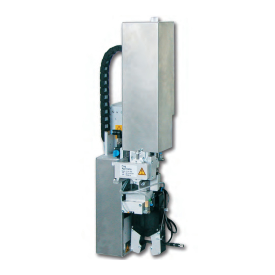
CAB 4712 Service Manual
Flag applicator
Hide thumbs
Also See for 4712:
- Assembly instructions manual (30 pages) ,
- Operator's manual (13 pages) ,
- Service manual (43 pages)
Table of Contents
Advertisement
Quick Links
Advertisement
Table of Contents

Related Manuals for CAB 4712


Summary of Contents for CAB 4712
- Page 1 Service Manual Flag Applicator 4712 Made in Germany...
- Page 2 Edition: 03/2020 - Part No. 9009954 Copyright This documentation as well as translation hereof are property of cab Produkttechnik GmbH & Co. KG. The replication, conversion, duplication or divulgement of the whole manual or parts of it for other intentions than its original intended purpose demand the previous written authorization by cab.
-
Page 3: Table Of Contents
Table of Contents Introduction ............................5 Instructions ............................... 5 Intended Use ............................5 Safety Instructions ............................ 5 Safety Markings ............................6 Environment ............................. 6 Product Description ..........................7 Important Features ........................... 7 Technical Data ............................7 Device Overview without Cover ....................... 8 Contents of Delivery .......................... - Page 4 Electronics Retainer Assembly ....................... 46 Guiding Cylinder Z Assembly ......................... 47 Cylinder Z Assembly ..........................48 Pliers Assembly ............................49 Drawings ............................... 50 Block diagram ............................50 Pneumatic drawing Type 4712 ....................... 51 Test Report ............................52 Index ..............................53...
-
Page 5: Introduction
• The device is designed to use on a cab printer of the HERMES Q series. Any other use or use going beyond this shall be regarded as improper use. The manufacturer/supplier shall not be liable for damage resulting from unauthorized use;... -
Page 6: Safety Markings
Introduction • In operation, moving parts are easily accessible. This applies especially for the zone, where the pad is moved between the starting and the labelling position. During operation do not reach into that zone and keep long hair, loose clothes, and jewelry distant. Before any manipulations in those areas, close the shutoff valve. -
Page 7: Product Description
Flag length L Flag length L α α Fig. 2 Applicator parameters Form pad Technical data 4712 L 300 Label width Hermes + 4 60 - 100 Label transfer method Label height 10 - 50 Form-pad Diameter 3 - 16... -
Page 8: Device Overview Without Cover
Product Description Device Overview without Cover Front view Throttle valves vacuum/support air Fig. 3 Overview - Front View 10 Screw to fix the pad position X/Z 1 Throttle valve cylinder Z- movement inside 2 Cylinder 'Z' 11 Cylinder 'Peel position' 3 Knurled screw for attaching the applicator on the 12 Pad assembly printer 13 Blowtube for Support Air... - Page 9 Product Description Back view Valves and control unit (without tubes) Fig. 4 Overview - Rear View Fig. 5 Overview - Control System Throttle valve cylinder Z- movement inside Magnetic Valve Cylinder 'Z' Magnetic Valve Cylinder 'flag' Throttle valve cylinder Z- movement outside Blowtube for Support Air Magnetic Valve Cylinder 'peel position / Locking for hinges Cylinder 'pliers'...
-
Page 10: Contents Of Delivery
Product Description Contents of Delivery • Applicator with mounted pad assembly (1) • Adjustment tool for the pads (2) • Blow tube for supporting air (3) (depend of the used printer) • Air pressure regulation unit (4) • Documentation and test report Fig. -
Page 11: Configuration On The Printer
Configuration on the Printer The method of use of the applicator can be modified by altering the parameter settings. The most important setting is the choice between the mode "stamp" and "blow." Besides that the applicator has different sequences of printing and applying labels in a labeling cycle. The flag applicator will activate in the mode of operation Blow pursued around all necessary parameters and to be able to modify. -
Page 12: Configuration Parameters Of The Applicator
Configuration on the Printer Configuration Parameters of the Applicator Start menu. Setup > Labelling. Select Parameter Meaning Default Transfer mode Setting the operation mode Blow on Blow on Cycle sequence Print-Apply Setting the application mode Print-Apply : An external start signal releases the print of a label and following the application of the label. -
Page 13: Setting The Peel Position
Configuration on the Printer Setting the Peel Position To optimize the transfer of the labels from the printer to the pad there are two different parameters available for adjusting the peel position. Attention! First adjust the parameter "Peel Position" in the printer configuration. Then adjust the additional peel-off offset in the software. It is very important to follow that procedure for a certain start after label loading and for the re-start after error treatment. -
Page 14: Test Mode
Test Mode Test Mode without a Print Job Fig. 7 Display By alternating between buttons on the display it is possible to simulate the labeling process without an active printing job. Push button This causes the feed of an empty label. Simultaneously the vacuum of the pad as well as the supporting air are activated. -
Page 15: Installation
In the case of a customer specific setup with special material the settings can deviate from the standard values. In this case the standard values in the setup protocol are as follows. The factory default settings are: Connected to a cab HERMES Q printer, vertical Pressure value of the compressed air: 0,45 MPa (4,5 bar) Vacuum -0,06 MPa (-0,6 bar) -
Page 16: Tools
To change the throttle valves SW 13 Setting the spring power on the adapter bolt SW20 Changing the cylinder Adjustment tool for the pads cab Art.-Nr.: Mounting the pads 597285 Manometer ± 7 bar Pressure air measurement Table 3 Tools... -
Page 17: Mounting And Demounting The Cover
Installation Mounting and Demounting the Cover To initialize the applicator or perform adjustments it is required to remove the cover. Once content with the changes reattach the cover. Warning! It is only permitted to use the applicator with a mounted cover (2). Only in the case of servicing, adjustments and maintenance may the cover be removed. -
Page 18: Mounting The Applicator
Installation Mounting the Applicator Fig. 11 Mounting applicator on printer Attention! Initiation, adjustments and changing of parts is only for qualified service personal only. Mount the applicator 1. Hang the applicator with the female part of hinges (1) at the printer mounted hinges parts (2). 2. Connect SUB-D 15 male connector (6) to the female connector (7) of the printer. 3. -
Page 19: Releasing The Transportation Lock
Installation Releasing the Transportation Lock Before the applicators are delivered, a transportation lock (4) is mounted on the rod (1). For the labeling operation, the transport lock (4) is pushed onto the stopper (2). The stopper (2) brakes the lifting movement and triggers the flag formation. Releasing the transportation lock 1. Loosen the screw (3) of the transport lock (2). 2. -
Page 20: Adjustments
Adjustments Compressed Air Connection Attention! Adjustments and functionality control were done with a compressed air value of 4.5 bar. The applicator's operating range is between 4.0 and 6.0 bar. Warning! When connecting the applicator to compressed air it is considered "IN USE!" Cylinder motion is possible! ... -
Page 21: Mounting The Suction Pads
1. Loosen screws (3). 2. Use the adjusting tool (6) included (cab serial No.: 5972857) as shown in the picture to adjust the suction plates. 3. Slide each suction plate (4) over the corresponding driving pin (2) to the adjusting tool (6). -
Page 22: Adjusting The Pad
Adjustments Adjusting the Pad For the perfect application of labels it is necessary that the pad is placed precisely above the dispensed label. Aligning the pad parallel to the dispensing plate The edge of the pad should be positioned parallel to the dispensing plate of the printer in order to position the label exactly on the pad. -
Page 23: Moving The Pad In Y-Direction
Adjustments 6.4.1 Moving the Pad in Y-Direction 1 mm Fig. 18 Displacement in the Y direction Displacement in the Y direction (printing direction) 1. Switch off the compressed air and pull the tube out of the throttle valve (5). The cylinder extends by spring force and is in the label transfer position. -
Page 24: Moving The Pad In Z-Direction
Adjustments 6.4.2 Moving the Pad in Z-Direction Fig. 19 Displacement in the Z direction Displacement in the Z direction (Height) 1. Switch off the compressed air and pull the tube out of the throttle valve (4). The cylinder extends by spring force and is in the label transfer position. -
Page 25: Moving The Pad In X-Direction
Adjustments 6.4.3 Moving the Pad in X-Direction Fig. 20 Displacement in the Y direction Displacement in the X direction (Side) 1. Loosen screw (3) on the binder (5). 2. Move cylinder assembly with the pad along the crossbeam (4) so that the dispensed label (7) is aligned centrally to the pad (6). -
Page 26: Alignment Of The Product To The Applicator
Adjustments Alignment of the Product to the Applicator Depending on the orientation of the applicator to the printer the alignment of the product will take place Note! For optimal alignment of the product for labeling a fixed uptake of the product is necessary. Printing direction Edge of pad (pad axis) (dispensing plate of the printer) 90°... -
Page 27: Setting The Application Height
Adjustments Setting the Application Height Dismount the cover „5.4 Mounting and Demounting the Cover“ Place the product in the product-holder Switch off the compressed air. Pull the tubes out of the main cylinder Z-direction to be able to move the pliers manually. ... -
Page 28: Adjusting The Vacuum
Adjustments Adjusting the Vacuum Via the negative pressure the label is fixed to the applicator. This vacuum needs to be strong enough to hold the label and cover all suction apertures. It may not be strong enough to hinder the transport of the from the printer to the applicator. This is dependent on the label material used. The default value of the vacuum is -0.6 bar. Note! By adjusting the vacuum it is possible to prevent the label from being applied to the product. -
Page 29: Adjustments To The Blowtube (Supporting Air)
Adjustments Adjustments to the Blowtube (Supporting Air) For optimal support during the acquisition of the label of the applicator the supporting air is to be set up so that it is free of turbulence and evenly pushes the label against the pad. The default air pressure value is set to 2 bar. -
Page 30: Adjustment On The Pressure Reduce Valve Cylinder Flag
Adjustments Measuring point (MP S) for Supporting Air. With a Manometer that is capable of measuring pressures ranging from -7 to 7 bar the effective pressures can be measured. MP S: Support air (desired default value 2 bar) 1. Remove the cover and interpose the manometer at the MP S . -
Page 31: Set Throttle Valves On The Cylinders
Adjustments 6.10 Set Throttle Valves on the Cylinders Exhaust throttle valves are installed on the cylinders of the applicator. The valves control the movement of the cylinders in the direction of the valves. move in direction move out direction of the piston of the piston Fig. -
Page 32: Set Cylinder Z / Actor 1
Adjustments 6.12 Set Cylinder Z / Actor 1 6.12.1 Set cylinder 'Z' throttle valves Throttle valve (1.01) movement inside 1.01 Marker on the tube with the number 1 Close the throttle valve (1.01) completely. Turn the set screw clockwise until it stops. If no different value is noted in the test report, open the throttle valve (1.01) by turning it 9 turns counterclockwise. -
Page 33: Setting Of The End Position Dampener
Adjustments 6.13 Setting of the End Position Dampener Note! The end position dampening of the lifting cylinders are set by default and will normally not need to be adjusted. The end position dampening of the cylinder z is for relief of mechanical strain particularly at higher speeds or when using a larger mass. -
Page 34: Set Cylinder Flag / Actor 2
Adjustments 6.14 Set Cylinder Flag / Actor 2 Set Cylinder 'flag' throttle valves 6.14.1 Throttle valve (2.04) movement inside Marker on the tube with the number 3 Close the throttle valve (2.04) completely. Turn the set screw clockwise until it stops. If no different value is noted in the test report, open the throttle valve (1.01) by turning it 8 turns counterclockwise. -
Page 35: Removing The Pliers Assembly
Adjustments 6.14.3 Removing the pliers assembly To change the cylinder lug or the connecting rod linkage, the pliers assembly (5) must be dismounted. Fig. 38 Dismounting the pliers assembly First pull all tubes (2/3) coming from the valve block out of the connectors. These are provided with number markers and can be reassigned based on the instructions for the throttle valves of the cylinders and the pneumatic plan after reassembly. -
Page 36: Dismounting The Pliers Assembly
Adjustments 6.14.4 Dismounting the pliers assembly If it is necessary to change the lifting cylinder flag (2) or the connecting rod (14), the following assemblies must be removed from the dismounted assembly 'pliers'. Fig. 39 Disassemble the pliers assembly Disassemble the pads (1). Loosen and pull out the sensor (8). Loosen the screws (7) and remove the compact cylinder (6) from the holder of the base plate (1). - Page 37 Attention! Use only a plastic grease to grease the running surfaces on the guide. cab Part No.: 5984552.001 14.1 Move the rod linkage (14) with the groove on the center piece place to the guide (1.1) of the base plate (1).
- Page 38 Adjustments Place the cylinder 'pliers' (6) with the tappet (6.1) on the holder (1.3) of the base plate (1). Insert the tappet (6.1) in the recesses (15.1) of the pliers jaws (15). Attach the compact cylinder (6) with the screws (7) on the holder (1.3) of the base plate (1).
-
Page 39: Set Cylinder Pliers / Actor 3.1
Adjustments 6.15 Set Cylinder Pliers / Actor 3.1 6.15.1 Set throttle valves on cylinder 'pliers' Throttle valve (3.06) movement outside Marker on the tube with the number 6 Close throttle valve (3.06) completely. Turn the set screw clockwise until it stops. If no different value is noted in the test report, open the throttle valve (3.06) by turning it 8.5 turns counterclockwise. -
Page 40: Set Cylinder Peel Position / Actor 3.0
Adjustments 6.16 Set Cylinder Peel Position / Actor 3.0 6.16.1 Set throttle valves on cylinder 'peel position' Throttle valve (3.03) movement inside with silencer Close throttle valve (3.03) completely. Turn the set screw clockwise until it stops. If no different value is noted in the test report, open the throttle valve (3.03) by turning it 3 turns counterclockwise. -
Page 41: Failure
Failure Error Messages of the Printer For detailed information about printer errors (e.g. 'Paper out', 'Ribbon out', etc.) Check the operator's manual of the printer. Error treatment: Clearing the error results. Press the to synchronize the label feed, remove the left over labels manually. To quit the error state press Repeat . -
Page 42: Error Pattern
Failure Error Pattern No. Error pattern Possible error cause Troubleshooting The label is not centered on the pair of pads after Correct the pad position in delivery from the printer. the X direction In the basic position, pads are not aligned parallel to Align the pad precisely each other using the setting tool for... - Page 43 Failure No. Error pattern Possible error cause Troubleshooting electrostatic charge Install an external ionizing blower. Application height not correct Readjust the stopper Product too soft and flexible Clamp the product if possible. Fix the product on the supports In the basic position, pads are not aligned parallel to Align the pad precisely each other using the setting tool for...
-
Page 44: Spare Parts
Spare Parts Retainer Assembly Part-No. Description PU Note Serial No. Part-No. Description PU Note Serial No. from from 5902489.001 Screw DIN7984-M4x8 5964090.001 Interlock 5964429.001 Plate 5964129.001 Cover 5965963.001 Set Screw 5902021.001 Screw DIN7991-M3x6 5971908.001 Adapter Profile 5904544.001 Spring 5964367.001 Knurled Screw 5902837.001 Screw DIN7984-M4x8 5964036.001 Mounting Plate 5902167.001 Screw DIN912-M5x50... -
Page 45: Pneumatics Retainer Assembly
Spare Parts Pneumatics Retainer Assembly Part-No. Description PU Note Serial No. Part-No. Description PU Note Serial No. from from 5902489.001 Screw DIN7984-M4x8 5966413.001 Support 5964095.001 Blow Tube 4" 5906966.001 Push-in L-Connector 5902863.001 Screw DIN7984-M4x25 5902571.001 Screw DIN7984-M4x6 5905285.001 Push-in L-Connector 5976156.001 Valve Block 5905284.001 Shut-off valve 5907428.001 Magnetic Valve... -
Page 46: Electronics Retainer Assembly
Spare Parts Electronics Retainer Assembly Part-No. Description PU Note Serial No. Part-No. Description PU Note Serial No. from from 5966463.001 Tube Ø4 5964494.001 Sensor 5964595.001 Sensor 5902571.001 Screw DIN7984-M4x6 5902571.001 Screw DIN7984-M4x6 5966441.001 Sensor 5966417.001 Retainer 5966442.001 Sensor 5955586.001 Cable 5971449.001 Sensor 5964591.001 Cable 5971448.001 Sensor... -
Page 47: Guiding Cylinder Z Assembly
Spare Parts Guiding Cylinder Z Assembly Part-No. Description PU Note Serial No. Part-No. Description PU Note Serial No. from from 5964595.001 Sensor 5902572.001 Screw DIN7984 M4x16 5521159.001 Nut 5964343.001 Stopper 5907714.001 Shock Absorber 5964236.001 Tamp Retainer 5977413.001 Tansport Lock 5955707.001 Adapter Bolt 5965966.001 Sliding Carriage 72.1 5905069.001 Spring... -
Page 48: Cylinder Z Assembly
Spare Parts Cylinder Z Assembly Part-No. Description PU Note Serial No. Part-No. Description PU Note Serial No. from from 5902489.001 Screw DIN7984-M4x8 5902900.001 Screw DIN7984-M 6x20 5525920.001 Distance Bolt 4x15 5902837.001 Screw DIN7984-M4x8 5966460.001 Tube Ø4 5979604.001 Cable Guide 5964591.001 Cable 5964307.001 Guide Rail 5905593.001 Mounting Clip 5964494.001 Sensor... -
Page 49: Pliers Assembly
Spare Parts Pliers Assembly Part-No. Description PU Note Serial No. Part-No. Description PU Note Serial No. from from 5905604.001 Push-in L-Fitting 5907177.001 Cylinder 5902565.001 Screw DIN7984-M4x10 5966460.001 Tube Ø4 5966466.001 Tube Ø4 5902565.001 Screw DIN7984-M4x10 5902862.001 Screw DIN7984-M4x20 5979608.001 Holder 5966441.001 Sensor 5979602.001 Base Plate 5966442.001 Sensor... -
Page 50: Drawings
Drawings Block diagram EEPROM Applicator control CON 1 CON 1 SUB-D 9 Sensor start position Interface to the printer cylinder flag Applicator interfaces Sensor start position Sensor end position cylinder flag cylinder (1) Z Sensor end position Sensor cylinder pliers cylinder (1) Z Sensor cylinder peel position CON 2... -
Page 51: Pneumatic Drawing Type 4712
Drawings Pneumatic drawing Type 4712 Fig. 55 Pneumatic drawing Type 4712... -
Page 52: Test Report
(check scope of delivery), package labelled unit cleaned and boxed date: Index: 20.03.2020 Fig. 56 Test report example applicator 4712 Description in the test report Description in the im Document/Pneumatic drawing Cylinder 1 Cylinder (1) Z Cylinder 2 Cylinder (2) Flag Cylinder 3.0... -
Page 53: Index
Index Pad ...........22 Pad Assembly ........21 Adjusting tool ........21 Vacuum ..........28 Pad in X-Direction......25 Application Height......27 Vacuum throttle valve .......28 Pad in Y-Direction ......23 Values ex factory ......15 Pad in Z-Direction ......24 Valves and control unit .......9 Block diagram ........50 Parameters of the Applicator ....12 Blowtube ...........29 Peel-off Mode ........13...
Need help?
Do you have a question about the 4712 and is the answer not in the manual?
Questions and answers