Table of Contents
Advertisement
Quick Links
Advertisement
Table of Contents

Related Manuals for CAB 4614-200L


Summary of Contents for CAB 4614-200L
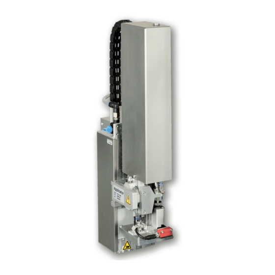
- Page 1 Service Manual Stroke-Blow Applicator 4614 MADE IN GERMANY...
- Page 2 9009626 Copyright This documentation as well as translation hereof are property of cab Produkttechnik GmbH & Co. KG. The replication, conversion, duplication or divulgement of the whole manual or parts of it for other intentions than its original intended purpose demand the previous written authorization by cab.
-
Page 3: Table Of Contents
Table of Contents Introduction ............................4 Instructions ............................... 4 Intended Use ............................4 Safety Instructions ............................ 4 Safety Marking ............................5 Environment ............................. 5 Product Description ..........................6 Important Features ........................... 6 Technical Data ............................6 Overview without cover ..........................7 Contents of Delivery .......................... -
Page 4: Introduction
• The device applicator mounted on a cab printer of the Hermes+ series is intended exclusively for applying suitable materials that have been approved by the manufacturer. Any other use or use going beyond this shall be regarded as improper use. -
Page 5: Safety Marking
Introduction • In operation, moving parts are easily accessible. This applies especially for the zone, where the pad is moved between the starting and the labelling position. During operation do not reach into that zone and keep long hair, loose clothes, and jewelry distant. Before any manipulations in those areas, close the shutoff valve. -
Page 6: Product Description
Product Description Important Features • The supporting air and the vacuum as well as the speed of the cylinder are adjustable. That way the applicator can be adapted to different label materials and sizes. • To avoid contamination within the vacuum channels they are cleaned by air pressure impulse at the end of each application. -
Page 7: Overview Without Cover
Product Description Overview without cover Front View Throttle valves Vacuum/Support air Drosselventile Vakuum/Stützluft Table 2 Overview - Front View Fig. 2 Throttle Valve Vacuum and Support Air 1 Throttle valve cylinder - move in Z-direction 8 Throttle valve cylinder - move out Z-direction 9 Screw to fix the horizontal pad position - X-direction 2 Stopper for the operation mode "Blow on", transport lock 3 Knurled screw for attaching the applicator to the... - Page 8 Product Description Back View Rückansicht Fig. 3 Overview - Back view Fig. 4 Overview - Control system 1 Throttle valve cylinder - move in Z-direction 18 Valve Cylinder Z Throttle valve cylinder - move out Z-direction 19 Cover plate 10 Pad - customized 20 Valve Blow air 12 Blow tube 21 Valve Vacuum and Support air...
-
Page 9: Contents Of Delivery
Product Description Contents of Delivery - Applicator (1) - Screws (part of the pad) (2) - Blow tube (as ordered) (3) - Pad (as ordered) (4) - Documentation Fig. 5 Contents of delivery Note! Please keep the original packaging in case the applicator needs to be returned. Attention! The device and printing materials will be damaged by moisture and wetness. -
Page 10: Operation
Operation Standard Operation Check all external connections. Load the material. Open the shutoff valve. Attention! Ensure that the pad is not covered by a label when switching on the printer-applicator system otherwise the vacuum sensor may be calibrated incorrectly. ... - Page 11 Operation Fig. 7 Mounting the applicator to the printer Attention! Initiation, adjustments and changing of parts is to be performed by qualified service personal only. „1.3 Safety Instructions“ Attention! Disconnect the printer from the power supply before mounting the applicator! Ensure a stable placement of the printer! Connect the compressed air only after mounting the applicator to the printer! To clean the applicator and printer it is sometimes necessary to turn away or even dismount the applicator from the printer.
-
Page 12: Error Messages
Error Messages Error messages of the printer For detailed information about printer errors Operator's manual of the printer Error treatment: Clearing the error results. Press the feed key to synchronize the label feed, remove the left over labels manually. ... -
Page 13: Installation
In the case of a customer specific setup with special material the settings can deviate from the standard values. In this case the standard values in the setup protocol are as follows. The factory default settings are: • Connecting on a cab Hermes+ printer, vertical • Used material for ex-factory settings: cab Part No.: 5556472 54x35.5 •... -
Page 14: Tools
Installation Tools Screwdriver with parallel blade To adjust the throttle valves Product sensor Hexagon key L-wrench To adjust the sensors (in delivery state of the applicator) or matched norm parts (in delivery state of the applicator)) Pad adjustments Changing pad Fllat-round nose - straight Mount/Dismount of tubes... -
Page 15: Mounting The Applicator
Installation Mounting the applicator Attention! Disconnect the printer from the power supply before mounting the applicator! Ensure a stable positioning of the printer! Connect the compressed air only after mounting the applicator to the printer! 1. Hang the applicator to the printer via the female hinges (1) to the male hinges (2) of the printer. -
Page 16: Mounting The Pad
Installation Mounting the Pad 1. Insert the two pins (9) on the pad (10) into the holes on the bottom of the pad holder (6). 2. Fix the pad (10) with the screws (4) to the pad holder (6). 3. Insert the vacuum tube (2) and the support air tube (3) into the appropriate push-in-fittings (7, 8) of the pad. -
Page 17: Connecting The Compressed Air
3 Open the stop valve (2) by turning it into the direction of air flow. 4 Switch on the printer by the power switch. It is possible to use an air pressure regulation unit. cab offers two versions of air pressure regulators. • Air pressure regulation unit with included magnetic valve (3) Controlling via printer ... -
Page 18: Adjustments
Adjustments Pad Adjustments For optimal functionality it is necessary to place the pad exactly over the label for the takeover procedure. Moving the pad in X-, Y- and Z-direction 1 mm Fig. 14 Moving the pad assembly Adjustment in the X-direction - sideways adjustment 1. -
Page 19: Vacuum Adjustments
Adjustments Vacuum Adjustments The label will be held on the pad by a vacuum. The vacuum needs to be set up in such a way that the label covers all the suction holes and is not hindered before it reaches its intended position on the pad. The default Value of the Vacuum is -0.6 bar. -
Page 20: Blow Tube And Support Air Adjustments
Adjustments Blow Tube and Support Air Adjustments The blow tube must be adjusted in such a way that the label takeover is unhindered by turbulence and the supporting air blows the label evenly against the pad. The default factory value is 2 bar. Note! When changing the label size (2", 4"... -
Page 21: Adjusting The Sensor On Cylinder Z
Adjustments Measuring point (MP S) of the Supporting Air Use a manometer with a measuring range of -7 to 7 bar to measure the pressure. MP S: Supporting Air (reference value 2 Bar) 1. Dismount cover and connect the manometer to the MP S. -
Page 22: Adjusting The Product Sensor
Adjustments Adjusting the Product Sensor The product sensor detects the labelling position of the pad in relation to the product. The adjustment of the product sensor is dependant on the operation mode - blow on. The detection distance of the sensor is 5 - 200 mm from the bottom edge of the sensor. Note! To apply the label correctly onto the product the distance be between pad and product may exceed 10 mm. -
Page 23: Lift Speed Of Cylinder Z
Adjustments Lift Speed of Cylinder Z Fig. 23 Throttle valves of cylinder Z The movement speed of the pad can be regulated via two throttle valves (1, 3). Adjust the pad movement speed as necessary. To increase the downward speed turn the screw (4) at the lower valve (3) counterclockwise. ... -
Page 24: End Position Dampening
Adjustments End Position Dampening Note! The end position dampening of the lifting cylinder is set to the clients specifications and, under normal circumstances, do not need to be adjusted. The end position dampening reduces mechanical strain, especially when the device operates at higher speeds and with larger masses and thus impact energy. The dampening should be set up in such a way that both ends of the cylinders motion are reached securely but with as little force as possible. -
Page 25: Configuration
Configuration The applicator can be operated in different ways. While the original process stays the same, the operation mode can be chosen from within the printer setup. The most important setting is the selection between the operation modes "Stamp on" and "Blow on". For the applicator 4614/16 the operation mode "Blow on"... -
Page 26: Configuration Parameters Of The Applicator
Configuration Configuration Parameters of the Applicator The configuration parameters of the applicator can be found in the menu Setup > Machine param. Default Parameter Meaning Applicator Configuration parameters of the applicator > Mode of oper. Setting the operation mode stamp on, roll on, blow on. Stamp on > Mode of appl. Setting the application mode Print-Apply/Apply-Print Print- Apply Print-Apply: An external start signal begins the printing of a label followed by the... -
Page 27: Setting The Peel Position
Configuration Setting the Peel Position To optimize the transfer of the labels from the printer to the pad there are two different parameters available for adjusting the peel position. Attention! First adjust the parameter "Peel Position" in the printer configuration. Then adjust the additional peel-off offset in the software. Following this order is important for a problem free initiation after loading material and when treating errors. -
Page 28: Test Operation
Test Operation Test Mode without Print Job Warning! The pad will be moved to the starting position immediately! Danger of injury to hands and fingers by the moving pad! Do not reach into the zone of the moving pad and keep long hair, loose clothes, and jewelry away. Fig. 28 Test mode with the enter button Note! ... -
Page 29: Spare Parts
Spare Parts Retainer Assembly Part No. Description PU Note Serial No. Part No. Description PU Note Serial No. from from 5902489.001 Screw DIN7984-M4x8 5902021.001 Screw DIN7991-M3x6 5964129.001 Cover 12.1 5964036.001 Mounting Plate 12.2 5964185.001 Mounting Plate 5965963.001 Set Screw 13.1 5964318.001 Adapter Profile 5904544.001 Spring 13.2 5970013.001 Adapter Profile 5964367.001 Knurled Screw... -
Page 30: Pneumatics Retainer Assembly
Spare Parts Pneumatics Retainer Assembly Part No. Description PU Note Serial No. Part No. Description PU Note Serial No. from from 5902489.001 Screw DIN7984-M4x8 28.1 5976156.001 Valve Block 5902863.001 Screw DIN7984-M4x25 28.2 5976157.001 Valve Block 5906021.001 Magnetic Valve 5905285.001 Push-in L-Connector 5905284.001 Shut-off valve 5906022.001 Magnetic Valve 5906842.001 Push-in/threaded Fitting... -
Page 31: Electronics Retainer Assembly
Spare Parts Electronics Retainer Assembly Part No. Description PU Note Serial No. Part No. Description PU Note Serial No. from from 5966463.001 Tube Ø4 42.1 5964454.001 Sensor 5955586.001 Cable 42.2 5964494.001 Sensor 42.3 5964495.001 Sensor 38.1 5964590.001 Cable 38.2 5964591.001 Cable 43.1 5971703.001 Cable Sensor 38.3 5964592.001 Cable 43.2 5971588.001 Cable Sensor... -
Page 32: Guiding Cylinder Assembly 200/300
Spare Parts Guiding Cylinder Assembly 200/300 Part No. Description PU Note Serial No. Part No. Description PU Note Serial No. from from 47.1 5979483.001 Stopper C/D/O 57.1 5964236.001 Tamp Retainer 48.1 5979353.001 Stopper 57.2 5964241.001 Tamp Holder 5979327.001 Adapter Rail 49.1 5979331.001 Guide Rail with Carriage 49.2 5979342.001 Guide Rail with Carriage 5964351.001 Stopper. -
Page 33: Guiding Cylinder Assembly 400
Spare Parts Guiding Cylinder Assembly 400 Part No. Description PU Note Serial No. Part No. Description PU Note Serial No. from from 47.2 5964343.001 Stopper 60.2 5964240.001 Plate 48.2 5964364.001 Stopper 60.4 5964244.001 Plate 5902138.001 Screw DIN912-M5x10 5964061.001 Set Screw 5903505.001 E-Ring DIN6799-5 5964311.001 Adapter Bolt 5902827.001 Screw DIN7984-M5x25... -
Page 34: Cylinder Assembly Z 200/300
Spare Parts Cylinder Assembly Z 200/300 Part No. Description PU Note Serial No. Part No. Description PU Note Serial No. from from 5902489.001 Screw DIN7984-M4x8 5964443.001 Bolt 5966460.001 Tube Ø4 5964489.001 Knurled Nut 5905593.001 Mounting Clip 5966464.001 Tube Ø6 5966465.001 Tube Ø8 74.1 5964440.001 Cover 38.1 5964590.001 Cable 74.2 5964451.001 Cover... -
Page 35: Cylinder Assembly Z 400
Spare Parts Cylinder Assembly Z 400 Part No. Description PU Note Serial No. Part No. Description PU Note Serial No. from from 5902489.001 Screw DIN7984-M4x8 5906636.001 One-way Flow Control Valve 5966460.001 Tube Ø4 77.3 5906117.001 Cylinder 5902837.001 Screw DIN7984-M4x8 5966464.001 Tube Ø6 38.3 5964592.001 Cable 79.2 5909043.001 Screw DIN7984-M6x20 42.3 5964495.001 Sensor... -
Page 36: Drawings
Drawings 10.1 Block Diagram Type 4614/16 Controller Applicator Control CON 1 CON 1 SUB-D 9 Interface To Printer Applicator Interfaces Sensor Start Position Cylinder Z Product Sensor CON 2 CON 1 Valve Block Fig. 36 Block diagram 4614/4616... -
Page 37: Pneumatic Drawing Type 4614/16
Drawings 10.2 Pneumatic drawing Type 4614/16 Fig. 37 Pneumatics Type 4614/4616... -
Page 38: Label Position Type 4614 L
Drawings 10.3 Label Position Type 4614 L Fig. 38 Label position Type 4614 L... -
Page 39: Label Position Type 4614 R
Drawings 10.4 Label Position Type 4614 R Fig. 39 Label position Type 4614 R... -
Page 40: Index
Index Applicator Control ......34 Sensor Start Position ......21 Applicator Interfaces ......34 Sicherheitskennzeichnung....5 Arbeitsdruck........6 Stopper ..........24 Support Air Reading Points ......21 Bestimmungsgemäß......4 Block Diagram ........34 Tools ..........14 Blow on ..........25 Blow Tube .........16 Vacuum ..........19 Compressed Air ........17 Controller ..........34 X-direction ........18 Cover ..........14 Cylinder Assembly Guiding (Spare Parts) ....32...
Need help?
Do you have a question about the 4614-200L and is the answer not in the manual?
Questions and answers