CAB 4712 Assembly Instructions Manual
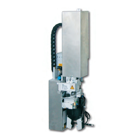
Flag applicator
Hide thumbs
Also See for 4712:
- Service manual (53 pages) ,
- Operator's manual (13 pages) ,
- Service manual (43 pages)
Table of Contents
Advertisement
Quick Links
Advertisement
Table of Contents

Related Manuals for CAB 4712


Summary of Contents for CAB 4712
- Page 1 Assembly Instructions Flag Applicator 4712 Made in Germany...
- Page 2 Edition: 03/2020 - Part No. 9009954 Copyright This documentation as well as translation hereof are property of cab Produkttechnik GmbH & Co. KG. The replication, conversion, duplication or divulgement of the whole manual or parts of it for other intentions than its original intended purpose demand the previous written authorization by cab.
-
Page 3: Table Of Contents
Table of Contents Introduction ............................4 Instructions ............................... 4 Intended Use ............................4 Safety Instructions ............................ 4 Safety Markings ............................5 Environment ............................. 5 Product Description ..........................6 Important Features ........................... 6 Technical Data ............................6 Product Overview ............................. 7 Contents of Delivery .......................... -
Page 4: Introduction
• The device is designed to use on a cab printer of the HERMES Q series. Any other use or use going beyond this shall be regarded as improper use. The manufacturer/supplier shall not be liable for damage resulting from unauthorized use;... -
Page 5: Safety Markings
Introduction • Before mounting the delivered components disconnect the printer from the power supply and close the shutoff valve of the applicator. • Only connect the device to other devices which have a protective low voltage. • Switch off all affected devices (computer, printer, accessories) before connecting or disconnecting. •... -
Page 6: Product Description
Flag length L Flag length L α α Fig. 2 Applicator parameters Form pad Technical data 4712 L 300 Label transfer method Form-pad Label width Hermes + 4 60 - 100 Label height 10 - 50 Label width in mm for... -
Page 7: Product Overview
Product Description Product Overview Fig. 3 Product Overview 1 Cover 6 Cylinder peel position 2 Compressed air connector 7 Compact cylinder Pliers 3 Shutoff valve 8 Tamp group 4 Short stroke cylinder - tamp / flag 9 Blow tube 5 Main stroke cylinder 10 Pair of tamps... -
Page 8: Contents Of Delivery
Product Description Contents of Delivery • Applicator with mounted tamp assembly (1) • Adjustment tool for the tamps (2) • Blow tube for supporting air (3) (depend of the used printer) • Air pressure regulation unit (4) • Documentation and test protocol Fig. -
Page 9: Implementing
SW 5.5 90° To change the pliers aperture SW 8 To change the throttle valves SW 13 Setting the spring power on the adapter bolt SW20 Changing the cylinder Adjustment tool for the tamps cab part No.: Mounting the tamps 597285... -
Page 10: Mounting The Applicator
Implementing Mounting the Applicator Fig. 6 Mounting applicator on printer Attention! Initiation, adjustments and changing of parts is only for qualified service personal only. Service Manual Mount the applicator 1. Hang the applicator with the female part of hinges (1) at the printer mounted hinges parts (2). 2. -
Page 11: Mounting And Demounting The Cover
Implementing Mounting and Demounting the Cover To initialize the applicator or perform adjustments it is required to remove the cover. Once content with the changes reattach the cover. Warning! It is only permitted to use the applicator with a mounted cover (2). Only in the case of servicing, adjustments and maintenance may the cover be removed. -
Page 12: Configuration On The Printer
Implementing Configuration on the Printer The method of use of the applicator can be modified by altering the parameter settings. The most important setting is the choice between the mode "stamp" and "blow." Besides that the applicator has different sequences of printing and applying labels in a labeling cycle. The flag applicator will activate in the mode of operation Blow pursued around all necessary parameters and to be able to modify. -
Page 13: Configuration Parameters Of The Applicator
Implementing Configuration Parameters of the Applicator 3.6.2 Start menu. Setup > Labelling. Select Parameter Meaning Default Transfer mode Setting the operation mode Blow on Blow on Cycle sequence Print-Apply Setting the application mode Print-Apply : An external start signal releases the print of a label and following the application of the label. -
Page 14: Compressed Air Connection
Implementing Compressed Air Connection Attention! Adjustments and functionality control were done with a compressed air value of 4.5 bar. The applicator's operating range is between 4.0 and 6.0 bar. Warning! When connecting the applicator to compressed air it is considered "IN USE!" Cylinder motion is possible! ... -
Page 15: Mounting The Suction Pads
1. Loosen screws (3). 2. Use the adjusting tool (6) included (cab serial No.: 5972857) as shown in the picture to adjust the suction plates. 3. Slide each suction plate (4) over the corresponding driving pin (2) to the adjusting tool (6). -
Page 16: Preparing The Tamp Assembly For Adjustments
Implementing Attention! All pneumatic settings have been made and optimized in the factory. Settings are only when changing corresponding components. according to the commissioning test report included in the scope of delivery. Settings must then be made by using the test report. -
Page 17: Adjusting The Pad
Implementing 3.12 Adjusting the Pad For the perfect application of labels it is necessary that the pad is placed precisely above the dispensed label. Aligning the pad parallel to the dispensing plate The edge of the pad should be positioned parallel to the dispensing plate of the printer in order to position the label exactly on the pad. -
Page 18: Moving The Pad In Y-Direction
Implementing 3.12.1 Moving the Pad in Y-Direction 1 mm Fig. 14 Displacement in the Y direction Displacement in the Y direction (printing direction) 1. Switch off the compressed air and pull the tube out of the throttle valve (5). The cylinder extends by spring force and is in the label transfer position. -
Page 19: Moving The Pad In Z-Direction
Implementing 3.12.2 Moving the Pad in Z-Direction Fig. 15 Displacement in the Z direction Displacement in the Z direction (Height) 1. Switch off the compressed air and pull the tube out of the throttle valve (4). The cylinder extends by spring force and is in the label transfer position. -
Page 20: Moving The Pad In X-Direction
Implementing 3.12.3 Moving the Pad in X-Direction Fig. 16 Displacement in the Y direction Displacement in the X direction (Side) 1. Loosen screw (3) on the binder (5). 2. Move cylinder assembly with the pad along the crossbeam (4) so that the dispensed label (7) is aligned centrally to the pad (6). -
Page 21: Setting The Peel Position
Implementing 3.13 Setting the Peel Position To optimize the transfer of the labels from the printer to the pad there are two different parameters available for adjusting the peel position. Attention! First adjust the parameter "Peel Position" in the printer configuration. ... -
Page 22: Adjustments To The Blow Tube (Supporting Air)
Implementing 3.15 Adjustments to the Blow Tube (Supporting Air) For optimal support during the acquisition of the label of the applicator the supporting air is to be set up so that it is free of turbulence and evenly pushes the label against the pad. The default air pressure value is set to 2 bar. -
Page 23: Adjusting The Vacuum
Implementing 3.16 Adjusting the Vacuum Via the negative pressure the label is fixed to the applicator. This vacuum needs to be strong enough to hold the label and cover all suction apertures. It may not be strong enough to hinder the transport of the from the printer to the applicator. This is dependent on the label material used. The default value of the vacuum is -0.6 bar. Note! By adjusting the vacuum it is possible to prevent the label from being applied to the product. -
Page 24: Alignment Of The Product To The Applicator
Implementing 3.17 Alignment of the Product to the Applicator Depending on the orientation of the applicator to the printer the alignment of the product will take place Note! For optimal alignment of the product for labeling a fixed uptake of the product is necessary. Printing direction Edge of tamp (tamp axis) -
Page 25: Setting The Application Height
Implementing 3.18 Setting the Application Height Dismount the cover „3.4 Mounting and Demounting the Cover“ Place the product in the product-holder Switch off the compressed air. Pull the tubes out of the main cylinder Z-direction to be able to move the pliers manually. ... -
Page 26: Operation
Operation Test Mode without a Print Job Fig. 24 Display By alternating between buttons on the display it is possible to simulate the labeling process without an active printing job. Push button This causes the feed of an empty label. Simultaneously the vacuum of the pad as well as the supporting air are activated. -
Page 27: Standard Operation
Operation Standard Operation Check all external connections. Load the material. Ensure that the locking system is locked "Operator's Manual" of the printer. Open the shutoff valve. Attention! Ensure that the pad is not covered by a label when switching on the printer-applicator system. Otherwise the vacuum sensor may be calibrated incorrectly. -
Page 28: Error Messages
Error Messages Error Messages of the Printer For detailed information about printer errors (e.g. 'Paper out', 'Ribbon out', etc.) Check the operator's manual of the printer. Error treatment: Clearing the error results. Press the to synchronize the label feed, remove the left over labels manually. To quit the error state press Repeat . -
Page 29: Licenses
+A11:2009+A12:2011+A1:2010+A2:2013 Person authorised to compile the technical file: Erwin Fascher Am Unterwege 18/20 99610 Sömmerda Signed for, and on behalf of the Manufacturer: Sömmerda, 08.07.2019 cab Produkttechnik Sömmerda Gesellschaft für Computer- und Automationsbausteine mbH Erwin Fascher 99610 Sömmerda Managing Director The product must not be put into service until the final machinery into which it is to be incorporated has been declared in conformity with the provisions of the Directive on machinery. -
Page 30: Eu Declaration Of Conformity
Annex II to Directive 2011/65/EU of the European Parliament and of the Council as regards the list of restricted substances Signed for, and on behalf of the Manufacturer: Sömmerda, 08.07.2019 cab Produkttechnik Sömmerda Gesellschaft für Computer- und Automationsbausteine mbH Erwin Fascher 99610 Sömmerda...
Need help?
Do you have a question about the 4712 and is the answer not in the manual?
Questions and answers