Table of Contents
Advertisement
Quick Links
Advertisement
Table of Contents

Related Manuals for CAB 4414 Series


Summary of Contents for CAB 4414 Series
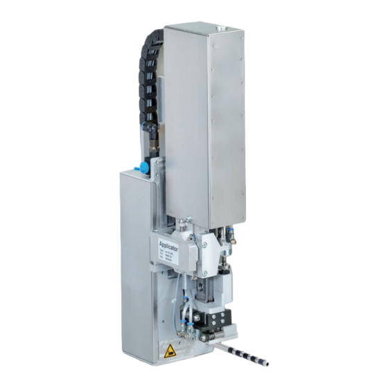
- Page 1 Service Manual Stroke Applicator 4414 MADE IN GERMANY...
- Page 2 Edition: 06/2021 - Part.-No. 9009206 Copyright This documentation as well as translation hereof are property of cab Produkttechnik GmbH & Co. KG. The replication, conversion, duplication or divulgement of the whole manual or parts of it for other intentions than its original intended purpose demand the previous written authorization by cab.
-
Page 3: Table Of Contents
Table of Contents Introduction ............................4 Instructions ............................... 4 Intended Use ............................4 Safety Instructions ............................ 4 Safety Marking ............................5 Environment ............................. 5 Product Description ..........................6 Important Features ........................... 6 Technical Data ............................6 Overview without a Cover ........................7 Contents of Delivery .......................... -
Page 4: Introduction
• The device is designed to use on a cab printer of the HERMES Q series. Any other use or use going beyond this shall be regarded as improper use. The manufacturer/supplier shall not be liable for damage resulting from unauthorized use;... -
Page 5: Safety Marking
Introduction Switch off all affected devices (computer, printer, accessories) before connecting or disconnecting. • • In operation, moving parts are easily accessible. This applies especially for the zone, where the pad is moved between the starting and the labelling position. During operation do not reach into that zone and keep long hair, loose clothes, and jewelry away. -
Page 6: Product Description
Product Description Important Features • The supporting air and the vacuum as well as the speed of the cylinder are adjustable. That way the applicator can be adapted to different label materials and sizes. • To avoid contamination within the vacuum channels they are cleaned by air pressure impulse at the end of each application. -
Page 7: Overview Without A Cover
Product Description Overview without a Cover Front view Throttle valves Vacuum/Support air Fig. 2 Device overview - front view 1 Throttle valve cylinder - move in Z-direction 8 Throttle valve cylinder - move out Z-direction 9 Screw to fix the vertical tamp position 2 Stopper for the operation mode "Blow on", transport lock 10 Throttle valve... - Page 8 Product Description Rear view Valves and control system Fig. 3 Device overview - rear view Fig. 4 Device overview - control system 1 Throttle valve cylinder - move in Z-direction 22 Valve Cylinder Z Throttle valve cylinder - move out Z-direction 23 Valve Cylinder X/Y 17 Sensor "Start Position"...
-
Page 9: Contents Of Delivery
Product Description Contents of Delivery 1 Applicator 2 Screws (part of the pad) 3 Blow tube (as ordered) 4 Pad (as ordered) 5 Documentation Fig. 5 Contents of delivery Note! Please keep the original packaging in case the applicator must be returned. Attention! The device and printing materials will be damaged by moisture and wetness. -
Page 10: Operation
Operation Standard Operation Check all external connections. Load the material. Ensure that the locking system is locked "Operator's Manual" of the printer. Open the shutoff valve. Attention! Ensure that the pad is not covered by a label when switching on the printer-applicator system. Otherwise the vacuum sensor may be calibrated incorrectly. - Page 11 Operation Fig. 7 Mounting applicator on printer Attention! Initiation, adjustments and changing of parts is only for qualified service personal only. Attention! Disconnect the printer from the power supply before mounting the applicator! Ensure the printer is standing in a stable, secure position! Connect the compressed air only after mounting the applicator to the printer! To clean the applicator and printer it is sometimes necessary to turn away or even dismount the applicator from the printer.
-
Page 12: Error Messages
Error Messages Error Messages of the Printer For detailed information about printer errors (e.g. 'Paper out', 'Ribbon out', etc.) Check the operator's manual of the printer. Error treatment: Clearing the error results. Press the to synchronize the label feed, remove the left over labels manually. To quit the error state press Repeat. -
Page 13: Installation
In this case the standard values in the setup protocol are as follows. The factory default settings are: • Connected to a cab Hermes+ printer, vertical • Used Pad: cab part No.: 5963881 54x36 for L cab part No.: 5963878 54x36 for R •... -
Page 14: Mount And Dismount The Cover
Installation Mount and dismount the cover To initiate the applicator or for adjustments it is necessary to dismount the cover (2). After these adjustments have been completed remount the cover. Warning! Do not operate the applicator without the cover (2). ... -
Page 15: Mounting The Applicator To The Printer
Installation Mounting the Applicator to the Printer Fig. 10 Mounting applicator on printer Attention! Initiation, adjustments and changing of parts is only for qualified service personal only. Service Manual Mount the applicator 1. Hang the applicator with the female part of hinges (1) at the printer mounted hinges parts (2). 2. Connect SUB-D 15 male connector (6) to the female connector (7) of the printer. 3. -
Page 16: Mounting The Pad
Installation Mounting the Pad 1. Slide the pins (3) into the holes of pad (4) by lifting the pad to pad holder (1). 2. Fix the pad with the screws (2) to the pad holder (1). 3. Insert the vacuum tube (5) and the blowing air tube (6) into the appropriate push-in-fittings (7,8) of the pad. -
Page 17: Adjustments
Adjustments Adjusting the Pad For the perfect application of labels it is necessary that the pad is placed precisely above the dispensed label. Aligning the pad parallel to the dispensing plate The edge of the pad should be positioned parallel to the dispensing plate of the printer in order to position the label exactly on the pad. -
Page 18: Moving The Pad In Y-Direction
Adjustments 6.1.1 Moving the Pad in Y-Direction 1 mm Fig. 14 Displacement in the Y direction Displacement in the Y direction (printing direction) 1. Switch off the compressed air and pull the tube out of the throttle valve (5). The cylinder extends by spring force and is in the label transfer position. -
Page 19: Moving The Pad In Z-Direction
Adjustments 6.1.2 Moving the Pad in Z-Direction Fig. 15 Displacement in the Z direction 1. Switch off the compressed air and pull the tube out of the throttle valve (4). The cylinder extends by spring force and is in the label transfer position. 1. -
Page 20: Moving The Pad In X-Direction
Adjustments 6.1.3 Moving the Pad in X-Direction Fig. 16 Displacement in the Y direction Displacement in the X direction (Side) 1. Loosen screw (3) on the binder (5). 2. Move cylinder assembly with the pad along the crossbeam (4) so that the dispensed label is aligned centrally to the pad. -
Page 21: Set Throttle Valves On The Cylinders
Adjustments Set Throttle Valves on the Cylinders Exhaust throttle valves are installed on the cylinders of the applicator. The valves control the movement of the cylinders in the direction of the valves. move in direction move out direction of the piston of the piston Fig. -
Page 22: Vacuum Adjustments
Adjustments Vacuum Adjustments The label will be held on the pad by a vacuum. The vacuum needs to be set up in such a way that the label covers all the suction holes and is not hindered before it reaches its intended position on the pad. The default Value of the Vacuum is -0.6 bar. -
Page 23: Blow Tube (Support Air) Adjustments
Adjustments Blow Tube (Support Air) Adjustments The blow tube must be adjusted in such a way that the label takeover is unhindered by turbulence and the supporting air blows the label evenly against the pad. The default factory value is 2 bar. Note! When changing the label size (2", 4"... -
Page 24: Labelling Position Of The Tamp
Adjustments Measuring Point Support Air (MP S) of support air Use a manometer with a measurement area -7 to 7 bar for measurement the pressure. MP S : support air (reference value 2 bar) 1. Remove cover and connect the manometer on RP S. - Tube (2) from valve block to blow tube connector. -
Page 25: Adjustment Of The Stopper For Blow Mode
Adjustments Adjustment of the Stopper for Blow Mode Note! For operation mode "Blow on" only! The operation mode "Blow on" allows labelling without contact. The pad does not press on the product. The label will be blown from the pad onto the product over a distance of up to 10 mm. -
Page 26: Lift Speed Of Cylinder Z
Adjustments Lift Speed of Cylinder Z Fig. 26 Throttle valves on the cylinder Z The speed of the pad movement can be regulated by two throttle valves (1, 3). Adjust the pad movement speed as necessary. To increase the downward speed turn screw (4) at the lower valve (3) counterclockwise. ... -
Page 27: Sensors On Cylinder Z
Adjustments Sensors on Cylinder Z Fig. 27 Sensors on cylinder Z Sensor Start Position (3) Cylinder Z 1. Loosen screw (1) of sensor "Start Position" (3) and move the sensor so that the top edge of the sensor sits comfortably in the sensor holder. 2. -
Page 28: End Position Cushioning
Adjustments 6.10 End Position Cushioning Note! The end position cushioning on the cylinder is adjusted by factory at customer project values. It's not necessary to change it if you don't change the configuration. The end position cushioning of the main cylinder reduces the impact energy when the applicator is operating at high speeds and/or mass. -
Page 29: Lift Speed Of Cylinder X/Y
Adjustments 6.12 Lift Speed of Cylinder X/Y Fig. 33 One-Way Flow Control Valve on Cylinder X/Y Adjust lift speed as necessary. To push the movement out in X-direction turn the screw on throttle valve (1) counterclockwise. turning clockwise on throttle valve (1) reduces the speed (move out) in X-direction. -
Page 30: Labeling From Below - Changing The Spring Of The Impact Sensor
Adjustments 6.14 Labeling from Below - Changing the Spring of the Impact Sensor For fault free labeling in a side- or upward-motion it is necessary to change the spring of the impact sensor. The stronger spring prevents the unwanted triggering of the impact sensor due to the inertia of the cylinder and stamp assembly group. -
Page 31: Configuration
Configuration The applicator can be operated in different ways. While the original process stays the same, the operation mode can be chosen from within the printer setup. The most important setting is the selection between the operation modes "Stamp on" and "Blow on". Additionally the applicator has different application modes concerning the order of printing and applying within one labelling cycle Stamp on... -
Page 32: Configuration Parameters Of The Applicator
Configuration Configuration Parameters of the Applicator Start menu. Setup > Labelling. Select Parameter Meaning Default Transfer mode Setting the operation mode Stamp on, Roll on, Blow on Stamp on Cycle sequence Setting the application mode Print-Apply / Apply-Print Print-Apply Print-Apply: An external start signal releases the print of a label and following the application of the label. -
Page 33: Setting The Peel Position
Configuration Setting the Peel Position To optimize the transfer of the labels from the printer to the pad there are two different parameters available for adjusting the peel position. Attention! First adjust the parameter "Peel Position" in the printer configuration. Then adjust the additional peel-off offset in the software. It is very important to follow that procedure for a certain start after label loading and for the re-start after error treatment. -
Page 34: Test Operation
Test Operation Test Mode without a Print Job Fig. 38 Display By alternating between buttons on the display it is possible to simulate the labeling process without an active printing job. Push button This causes the feed of an empty label. Simultaneously the vacuum of the pad as well as the supporting air are activated. -
Page 35: Drawings
Drawings Block Diagram Type 4414 Controller Applicator Control CON 1 CON 1 SUB-D 9 Interface To Printer Applicator Interfaces Sensor Start Position Sensor 1 Cylinder X Cylinder Z Sensor Labeling Position Sensor 2 Cylinder Y Cylinder Z CON 2 CON 1 Valve Block Fig. -
Page 36: Pneumatic Drawing Type 4414
Drawings Pneumatic drawing Type 4414 Fig. 40 Pneumatics Type 4414... -
Page 37: Label Position Type 4414 L
Drawings Label position Type 4414 L Fig. 41 Label position 4414L... -
Page 38: Label Position Type 4414 R
Drawings Label position Type 4414 R Fig. 42 Label position 4414R... -
Page 39: Index
Index Abbau des Applikators ......16 Pad ..........17, 19 Adjustment of the Stopper ....27 Pad in X-Direction......22 Apply/Print ........34 Pad in Y-Direction ......20 Pad in Z-Direction ......21 Parameters ........34 Block Diagram ........37 Peel-off Mode ........35 Blowing air ........34 Peel Position........35 Blow on ........33, 34 Pneumatic.........38 Blow time ..........34 Print/Apply ........34...
Need help?
Do you have a question about the 4414 Series and is the answer not in the manual?
Questions and answers