Table of Contents
Advertisement
Quick Links
Advertisement
Table of Contents

Related Manuals for CAB 4014


Summary of Contents for CAB 4014
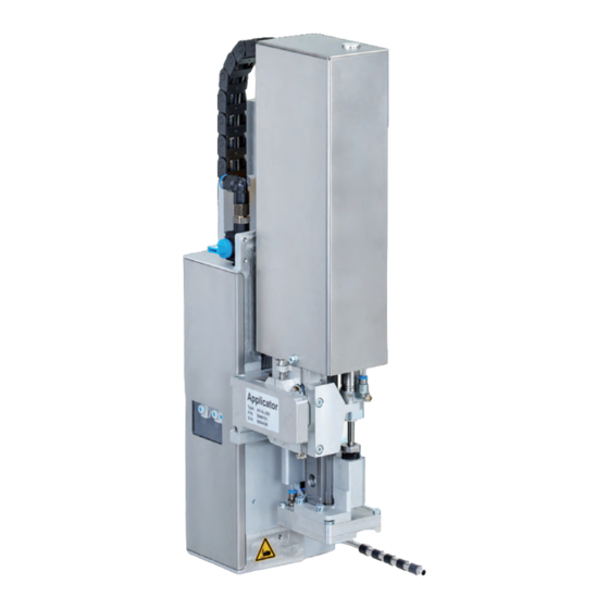
- Page 1 Service Manual Stroke Applicator 4014 / 4016 MADE IN GERMANY...
- Page 2 Edition: 02/2019 - Part No. 9009194 Copyright This documentation as well as translation hereof are property of cab Produkttechnik GmbH & Co. KG. The replication, conversion, duplication or divulgement of the whole manual or parts of it for other intentions than its original intended purpose demand the previous written authorization by cab.
-
Page 3: Table Of Contents
Table of Contents Introduction ............................5 Instructions ............................... 5 Intended Use ............................5 Safety Instructions ............................ 5 Safety Markings ............................6 Environment ............................. 6 Product Description ..........................7 Important Features ........................... 7 Technical Data ............................7 Overview without Cover ........................... 8 Contents of Delivery .......................... - Page 4 Cylinder Assembly Z 400 ........................40 Drawings ............................... 41 10.1 Block Diagram Type 4014/4016 ......................41 10.2 Pneumatic Drawing Type 4014/4016 ..................... 42 10.3 Label Position Type 4014 L/4016 L ......................43 10.4 Label Position Type 4014 R/4016 R ....................... 44 Index ..............................45...
-
Page 5: Introduction
• The device applicator mounted on a cab printer of the Hermes+ series is intended exclusively for applying suitable materials that have been approved by the manufacturer. Any other use or use going beyond this shall be regarded as improper use. -
Page 6: Safety Markings
Introduction • Before mounting the delivered components disconnect the printer from the power supply and close the shutoff valve of the applicator. • Only connect the device to other devices which have a protective low voltage. • Switch off all affected devices (computer, printer, accessories) before connecting or disconnecting. •... -
Page 7: Product Description
Tamp pad Universal pad Spring loaded Spring loaded tamp pad universal pad 4014/16 L/R 11F 4014/16 L/R 1100 4014/16 L/R 31F 4014/16 L/R 3100 Label width in mm for Hermes + 4 20 -114 75 - 90 80 - 114... -
Page 8: Overview Without Cover
Product Description Overview without Cover Front View Throttle valves vacuum/support air Fig. 2 Overview - Front View Fig. 3 Throttle Valve Vaccum and Support Airt 1 Throttle valve cylinder - move in Z-direction 8 Throttle valve cylinder - move out Z-direction 9 Screw to fix the vertical pad position 2 Stopper for the operation mode "Blow on", transport lock 3 Knurled screw for attaching the applicator on the printer... - Page 9 Product Description Rear View Fig. 4 Overview - Rear View Fig. 5 Overview - Control System 1 Throttle valve cylinder - move in Z-direction 19 Valve Cylinder Z Throttle valve cylinder - move out Z-direction 20 Cover plate 14 Sensor "Start Position" 21 Valve Blow air 15 Locking for hinges 22 Valve Vacuum and Support air...
-
Page 10: Contents Of Delivery
Product Description Contents of Delivery • Applicator (1) • Screws as part of the pad (2) • Blow tube - as ordered (3) • Pad - as ordered (4) • Pen to make holes (5) (only for universal pads) • Documentation Fig. -
Page 11: Pads
Product Description Pads 2.5.1 Universal Pads Universal Pad 4014L/R-1100 Spring-mounted Universal Pad 4014L/R-3100 Standard size : 70x60, 90x90 Standard size : 116x102, 116x152 Fig. 7 Universal pad 70x60 Fig. 8 Spring-mounted universal pad 116x152 Universal pads are available in different standard sizes. According to the size of the label the holes may be pierced into the tamp by the customer. -
Page 12: Operation
Operation Standard Operation Check all external connections. Load the material. Open the shutoff valve. Attention! Ensure that the pad is not covered by a label when switching on the printer-applicator system. Otherwise the vacuum sensor may be calibrated incorrectly. ... - Page 13 Operation Fig. 13 Mounting the applicator to the printer Attention! Initiation, adjustments and changing of parts is to be performed by qualified service personnel only. Service Manual of the Applicator Attention! Disconnect the printer from the power supply before mounting the applicator! Ensure the printer is in a stable position! Connect the compressed air only after mounting the applicator to the printer! To clean the applicator and printer it is sometimes necessary to turn away or even dismount the applicator from the printer.
-
Page 14: Error Messages
Error Messages Error Messages of the Printer For detailed information about printer errors (e.g. 'Paper out', 'Ribbon out', etc.) Check the operator's manual of the printer. Error treatment: Clearing the error results. Press the feed key to synchronize the label feed, remove the left over labels manually. ... -
Page 15: Installation
In this case the standard values in the setup protocol are as follows. The factory default settings are: • Connected to a cab Hermes+ printer, vertical • Used Pad: cab part No.: 5963881 54x36 for L cab part No.: 5963878 54x36 for R •... -
Page 16: Tools
Installation Tools Screwdriver with parallel blade To adjust the throttle valves and product sensor Hexagon key L-wrench To adjust the sensors (in contents of delivery) For matched norm parts (in contents of delivery) Pad adjustments Changing pad Flat-round nose To mount/dismount tubes straight angled Open spanner... -
Page 17: Mounting The Applicator To The Printer
Installation Mounting the Applicator to the Printer Attention! Disconnect the printer from the power supply before mounting the applicator! Ensure the printer is standing in a stable position! Connect the compressed air only after mounting the applicator to the printer! 1. -
Page 18: Mounting The Pad
Installation Mounting the Pad 1. Insert the pins (6) of the pad (8) into the holes on the bottom of the pad holder (7). 2. Fix the pad (8) to the pad holder (7) with the screws (1). 3. Insert the vacuum tube (2) and the air blowing tube (3) into their appropriate push-in-fittings (4 &... -
Page 19: Preparing The Applicator For The Spring Mounted Pad 401X-4X00
When delivered, the pad assembly is mounted in the lowest position as this is suited for most pads. In case of using a larger pad (e.g. 116x102/116x152) with the applicator 4014/4016 it is necessary to change the position of the pads z-direction. -
Page 20: Compressed Air Connection
4. Switch on the printer via the power switch. It is possible to use an air pressure regulation unit. cab offers two versions of air pressure regulators. • Air pressure regulation unit with included magnetic valve (3) Controlling via printer ... -
Page 21: Adjustments
Adjustments Pad Adjustments For optimal functionality it is necessary to place the pad exactly over the label for the takeover procedure. Moving the Pad in X-, Y- and Z-Directions 1 mm Fig. 22 Moving the pad assembly Adjustment in the X-direction - Sideways Adjustment 1. -
Page 22: Vacuum Adjustments
Adjustments Vacuum Adjustments The label will be held on the pad by a vacuum. The vacuum needs to be set up in such a way that the label covers all the suction holes and is not hindered before it reaches its intended position on the pad. The default Value of the Vacuum is -0.6 bar. -
Page 23: Adjusting The Blow Tube (Supporting Air)
Adjustments Adjusting the Blow Tube (Supporting Air) The blow tube must be adjusted in such a way that the label takeover is unhindered by turbulence and the supporting air blows the label evenly against the pad. The default factory value is 2 bar. Note! When changing the label size (2", 4"... - Page 24 Adjustments Fig. 27 Throttle valve "support air" The strength of the supporting air can be varied via the provided throttle valve (1). To increase the strength of the supporting air turn the throttle valve (1) counterclockwise. Measuring Point of the Supporting Air (MP S) Use a manometer with a measuring range of -7 to 7 bar to measure the pressure.
-
Page 25: Adjustment Of The Stopper For Blow On Mode
Adjustments Adjustment of the Stopper for Blow on Mode Note! For operation mode "blow on" only! The operation mode "Blow on" allows labelling without contact. The pad does not press on the product. The label will be blown from the pad onto the product over a distance of up to 10 mm. -
Page 26: Lifting Speed Of Cylinder Z
Adjustments Lifting Speed of Cylinder Z Fig. 30 Throttle valves of the cylinder Z The speed of the pad movement can be regulated by two throttle valves (1, 3). Adjust the pad movement speed as necessary. To increase the downward speed turn the screw (4) at the lower valve (3) counterclockwise. ... -
Page 27: Sensors On Cylinder Z
Adjustments Sensors on Cylinder Z 10 mm Fig. 31 Sensors on cylinder Z Sensor Start Position 1 1. Loosen screw (1) of sensor "Start Position" (3) and move the sensor so that the top edge of the sensor sits comfortably in the sensor holder. 2. -
Page 28: End Position Cushioning
Adjustments End Position Cushioning Note! The end position cushioning of the cylinder is set up to client specifications and does usually not need to be adjusted. The end position cushioning of the main cylinder reduces the impact energy when the applicator is operating at high speeds and/or masses. Adjust the end position cushioning so that the piston arrives the end position definitively but does not strike it to hard. A higher level of end position cushioning will reduce the lift speed. -
Page 29: Labeling From Below - Changing The Spring Of The Impact Sensor
Adjustments Labeling from below - Changing the Spring of the Impact Sensor For fault free labeling in a sideways- or upward-motion it is necessary to change the spring of the impact sensor. The stronger spring prevents the unwanted triggering of the impact sensor due to the inertia of the cylinder and stamp assembly group. -
Page 30: Configuration
Configuration The applicator can be operated in different ways. While the original process stays the same, the operation mode can be chosen from the printer setup. The most important setting is the selection between the operation modes "Stamp on", "Roll on" and "Blow on". Additionally the applicator has different application modes concerning the order of printing and applying within one labelling cycle. -
Page 31: Configuration Parameters Of The Applicator
> Hand-over up Take over the label directly from the dispensing edge with contact between pad and dispensing edge. Not applicable for Type 4014/4016 > Cleaning blow Activate/Deactivate - air pressure pulses to clean the pad > Vacuum delay On - The vacuum will switched on after the end of the label transport. -
Page 32: Setting The Peel Position
Configuration Setting the Peel Position To optimize the transfer of the labels from the printer to the pad there are two different parameters available for adjusting the peel position. Attention! First adjust the parameter "Peel Position" in the printer configuration. Then adjust the additional peel-off offset in the software. It is very important to follow that procedure for a certain start after label loading and for the re-start after error treatment. -
Page 33: Test Operation
Test Operation Test Mode without a Print Job Warning! The pad will be moved to the starting position immediately! Danger of injury to hands and fingers by the moving pad! Do not reach into the zone of the moving pad and keep long hair, loose clothes, and jewelry away. Fig. -
Page 34: Spare Parts
15.4 5964333.001 Crossbeam 8.2 5966531.001 Hinges 5964062.001 Binder 5964090.001 Interlock 17.1 5964310.001 Clamping Element 5903525.001 E-Ring DIN 6799-4 17.2 5964328.001 Clamping Element 11.1 5964429.001 Plate 11.2 5964438.001 Plate Note 401x L 401x R 4014 4016 Fig. 41 Retainer assembly - spare parts... -
Page 35: Pneumatics Retainer Assembly
Spare Parts Pneumatics Retainer Assembly Part-No. Description PU Note Serial No. Part-No. Description PU Note Serial No. from from 5907428.001 Magnetic Valve 5902489.001 Screw DIN7984-M4x8 5902863.001 Screw DIN7984-M4x25 5907429.001 Magnetic Valve 5905285.001 Push-in L-Connector 5906914.001 Push-in L-Connector 5905284.001 Shut-off valve 5906844.001 Vacuum Generator 5906842.001 push in/threaded fitting 5905257.001 Silencer... -
Page 36: Electronics Retainer Assembly
Spare Parts Electronics Retainer Assembly Part-No. Description PU Note Serial No. Part-No. Description PU Note Serial No. from from 5966463.001 Tube Ø4 42.1 5964454.001 Sensor Start Position Cyl.Z 5955586.001 Cable 42.2 5964494.001 Sensor Start Position Cyl.Z 38.1 5964590.001 Cable 42.3 5964495.001 Sensor Start Position Cyl.Z 38.2 5964591.001 Cable 43.1 5964490.001 Sensor End Position Cyl.Z 38.3 5964592.001 Cable... -
Page 37: Guiding Cylinder Assembly 200/300
Spare Parts Guiding Cylinder Assembly 200/300 Part-No. Description PU Note Serial No. Part-No. Description PU Note Serial No. from from 47.1 5979483.001 Stopper A/B/O 58.1 5979333.001 Plate 48.1 5979353.001 Stopper 58.2 5979419.001 Plate 5964061.001 Set Screw 5964351.001 Stopper. 51.1 5979349.001 Plate L/A/B 5902138.001 Screw DIN912-M5x10 51.2 5979417.001 Plate... -
Page 38: Guiding Cylinder Assembly 400
Spare Parts Guiding Cylinder Assembly 400 Part-No. Description PU Note Serial No. Part-No. Description PU Note Serial No. from from 43.1 5964490.001 Sensor End Position Cyl.Z 5521159.001 Nut 43.2 5964594.001 Sensor End Position Cyl.Z 57.1 5964236.001 Tamp Retainer 43.3 5964594.001 Sensor End Position Cyl.Z 57.2 5964241.001 Tamp Holder 5964343.001 Stopper 58.3 5964240.001 Plate... -
Page 39: Cylinder Assembly Z 200/300
Spare Parts Cylinder Assembly 200/300 Part-No. Description PU Note Serial No. Part-No. Description PU Note Serial No. from from 5964443.001 Bolt 5902489.001 Screw DIN7984-M4x8 5966460.001 Tube Ø4 5964489.001 Knurled Nut 5966464.001 Tube Ø6 75.1 5964440.001 Cover 38.1 5964590.001 Cable 75.2 5964483.001 Cover 38.2 5964591.001 Cable 75.4 5964451.001 Mounting Clip 42.1 5964454.001 Sensor Start Position Cyl.Z... -
Page 40: Cylinder Assembly Z 400
Spare Parts Cylinder Assembly 400 Part-No. Description PU Note Serial No. Part-No. Description PU Note Serial No. from from 5966460.001 Tube Ø4 5964489.001 Knurled Nut 5966464.001 Tube Ø6 75.3 5964484.001 Cover 38.3 5964592.001 Cable 75.6 5964485.001 Cover 42.3 5964495.001 Sensor Start Position Cyl.Z 5905593.001 Mounting Clip 5902047.001 Energy Track 5906636.001 One-way Flow Control Valve... -
Page 41: Drawings
Drawings 10.1 Block Diagram Type 4014/4016 Controller Applicator Control CON 1 CON 1 SUB-D 9 Interface To Printer Applicator Interfaces Sensor Start Position Cylinder Z Sensor Labeling Position Cylinder Z CON 2 CON 1 Valve Block Fig. 48 Block diagram 4014/4016... -
Page 42: Pneumatic Drawing Type 4014/4016
Drawings 10.2 Pneumatic Drawing Type 4014/4016 Fig. 49 Pneumatics type 4014/4016... -
Page 43: Label Position Type 4014 L/4016 L
Drawings 10.3 Label Position Type 4014 L/4016 L Fig. 50 Label position type 4014/4016 L... -
Page 44: Label Position Type 4014 R/4016 R
Drawings 10.4 Label Position Type 4014 R/4016 R Fig. 51 Label position type 4014/4016 R... -
Page 45: Index
Index Applicator Control ......41 Reading Point ........22 Applicator Interfaces ......41 Roll on ..........30 Block Diagram ........41 Sensor Start Position ......27 Blow Mode ........25 Stamp on ..........30 Blow on ..........30 Blow Tube .........19 Test Mode .........33 Tools ..........16 Cleaning ...........12 Controller ..........41 Universal Tamp Pad ......18 Cover ..........16 Cylinder Assembly...
Need help?
Do you have a question about the 4014 and is the answer not in the manual?
Questions and answers