Table of Contents
Advertisement
Advertisement
Table of Contents
Troubleshooting

Subscribe to Our Youtube Channel
Related Manuals for Ingenico iPP320


Summary of Contents for Ingenico iPP320
- Page 1 DIV351006 Rev 2 Telium Troubleshooting Guide Guide Telium Devices (iPP320, iPP350, iSC250, iSC350, iSC480, iSMPc, iSMP350, iUP250, and iWL250 Devices) Ingenico Inc. - 3025 Windward Plaza, Suite 600 - Alpharetta, GA 30005 Tel: (678) 456-1200 - Fax: (678) 456-1201 - www.ingenico.com...
- Page 2 Ingenico. Ingenico and the Ingenico logo are registered trademarks of Ingenico Corp. All other brand names and trademarks appearing in this guide are the property of their respective holders.
-
Page 3: Table Of Contents
Table of Contents 1_Introduction to the Telium Troubleshooting Guide ....... . 6 1_1 Conventions Used in this Manual . - Page 4 7_1 iPP320 and iPP350 Quick Reference ........
- Page 5 7_7_1 iWL250 Overview ................. . 51 7_7_2 iWL250 Power Requirements .
-
Page 6: 1_Introduction To The Telium Troubleshooting Guide
1_Introduction to the Telium Troubleshooting Guide This document is intended for use by customers’ support personnel to assist in the troubleshooting of Ingenico Telium devices in service. Along with helpful insights, the document provides step-by-step workflows for troubleshooting ease. Please refer to the... -
Page 7: 1_2 Assumptions
Operations and Product Support Guide 1_4 Support Procedures Before contacting Ingenico’s Technical Support or returning a device for repair, follow these procedures: Contact your Help Desk or Support Department first. Notate the issue, error code, and the process followed to troubleshoot the issue. -
Page 8: 1_5 Devices Covered In This Manual
Secure Access Modules and SIMs, micro SD cards, interface options and specifications. Device Quick Reference iPP320 iPP320 and iPP350 Quick Reference iPP350 iPP320 and iPP350 Quick Reference iSC250 iSC250 Quick Reference... -
Page 9: 1_6 Lcd Display Preservation For Telium Devices
1_6 LCD Display Preservation for Telium Devices Ingenico Telium PIN pad devices utilize backlit LCD displays to convey transaction and advertizing information. As with any LCD display, preventative actions are recommended in order to minimize the occurrence of image persistence. Image persistence occurs when an image is displayed for extended periods, leaving a temporary impression of the image on the screen which may be partially visible when the screen changes to a new image. -
Page 10: 2_General Troubleshooting
2_General Troubleshooting This section provides troubleshooting procedures for issues which may be encountered in the field. Troubleshooting procedures are organized and categorized as follows: Display Issues Security Issues Pen/Finger Response Issues Card Response Issues Communication Issues Error Messages If unable to restore the device to proper working condition by following the troubleshooting procedures, return the device for repair. Follow proper precautions for disconnecting and connecting cables to the terminal as provided in the Quick Reference located in the Appendices section of this document. -
Page 11: 2_2 Security Issues
Issue Cause/Error Recommended Action White Display or Verify that the correct power supply is used per specifications for this product. Rainbow Display Refer to the product Quick Reference Guide for this device in the Appendices. If (Multiple Colors) the correct power supply is being used then proceed to step 2. Reset power to the device and reinitialize the connection with the POS. -
Page 12: 2_3 Pen/Finger Response Issues
Issue Cause/Error Recommended Action PIN Entry Keys not injected Proceed to Encryption Validation Screen Does Not validate that a key is installed in Application goes offline (RBA) Display the device. If key is present, validate the key information and index are correct. Check your applications and key configuration index. -
Page 13: 2_4 Card Response Issues
Swipe the card in a reverse direction. For example, if swiping top to bottom, head swipe from bottom to top. If the device is experiencing frequent ‘Card Read Errors’, use an Ingenico approved card cleaner to clean the MSR readers. Contactless Light Not... -
Page 14: 2_5 Communication Issues
2_5 Communication Issues Refer to the below table for troubleshooting communications issues. Issue Cause/Error Recommended Action Device Locks Up or Reset power to the terminal. Wait until it completely initializes, then reset the POS "Freezes Up" to determine if communication can be reestablished. Access different screens to determine if the issue is consistent with a particular transaction or form. - Page 15 Issue Cause/Error Recommended Action ECC KO Replace the terminal. WAITING FOR Missing data (.dat) files or Reload the generic released application. DOWNLOAD application UNAUTHORIZED Replace the terminal. Replace the terminal. SIGNATURE Application is missing Reload the generic released application. SYSTEM Incorrect parameter settings Some or all of the required software may be missing.
-
Page 16: 3_Functions Overview
3_FUNCTIONS Overview The Functions menu allows the user to access menus to verify software and hardware configuration settings. This manual will review Telium Manager, Telium System Application (TSA), and Telium Download Application (TDA) menus to assist in the validation of your configuration. -
Page 17: 3_2 Navigating Menus
Wait until a second screen appears, and then press [ + ]. iPP3XX Press [ . ] key and Yellow key When splash screen displays during power up (for 2 seconds): Press [2], [6], [3], [4], and then press the green [Enter] key. Wait until a second screen appears, and then press [ + ]. -
Page 18: 4_Telium Manager Menu
4_Telium Manager Menu The Telium Manager menu is accessed via the FUNCTIONS main menu, and allows the user to verify hardware configuration settings. Refer to the below figure which shows the Telium Manager main menu. To verify contactless or MSR formats, refer to the following section: Verify Contactless and Magnetic Stripe Reader (MSR) Formats 4_1 Verify Contactless and Magnetic Stripe Reader (MSR) Formats The Telium Manager menu allows the user to verify that contactless is enabled and that the correct ISO format is selected for the... -
Page 19: 4_1_2 Msr Swipe (Iso)
When contactless is enabled, the first contactless LED will illuminate. This does not apply to the iSC480 with internal contactless. 4_1_2 MSR Swipe (ISO) ISO refers to the MSR tracks to be read. To verify that the correct ISO is selected, choose the [Initialization] option from the Telium Manager menu and follow the subsequent selections as illustrated in the below figure. -
Page 20: 5_Telium System Application (Tsa) Menu
5_Telium System Application (TSA) Menu The Telium System Application (TSA) menu allows the user to verify the presence of encryption keys and serial numbers. The TSA menu is accessed from the Functions main menu. Three menu options enable the user to verify that the encryption keys are present (Key Check Value, Master Session, and DUKPT) and provide details on the keys which are loaded. -
Page 21: 5_1_2 Injected Serial Number
An injected encryption key is also required for some MSR encryptions (e.g., Magtek, Monetra). MSR encryptions are enabled in the application. Ingenico’s devices support Master Session and DUKPT key formats. Encryption key formats are determined by the customer. Follow the validation instruction, per your format. Refer to the following sections for encryption validation:... -
Page 22: 5_2_1 Validating Special Keys
DUKPT KSN 5_2_1 Validating Special Keys To validate the Key Check Value (KTK), select the [KEY CHECK VALUE] option from the Telium System Application menu and follow the subsequent selections as illustrated in the below figure. Only the KTK value needs to be checked to ensure KTK encryption. - Page 23 23/57 Telium Troubleshooting Guide / June 28, 2014...
-
Page 24: 6_Telium Download Application (Tda) Menu
6_Telium Download Application (TDA) Menu The Telium Download Application (TDA) is an Ingenico application that can be used to perform the following functions: Configure communication port settings. Perform initial download and updates of software. Refer to the section Accessing the TDA Menu which will step you through the menu selection to verify or change settings for RS-232, Ethernet, Tailgate, and Bluetooth. -
Page 25: 6_1_1 Rs-232 (Serial) Setting
Ethernet Settings USB-HID Setting USB-CDC Setting Tailgate Settings Bluetooth Settings To reverse the steps taken in any of the above menus, and go back to the Telium Manager main menu, press the red [X] keypad button, then press the [+] or [F] keypad button. If the communication port settings are changed, press the [CANCEL] key several times in the Save and Reboot menu. -
Page 26: 6_1_2 Ethernet Settings
To change parity, from the SERIAL SETTINGS menu proceed as follows: To change flow control, from the SERIAL SETTINGS menu proceed as follows: 6_1_2 Ethernet Settings To view or reconfigure Ethernet port settings, select the [CONFIGURATION] option from the Telium Download Application menu and follow the subsequent selections as illustrated in the below figure. - Page 27 To set or change the DHCP setting, proceed as follows from the Ethernet Settings menu: To set or change the Host IP address, proceed as follows from the Ethernet Settings menu: 27/57 Telium Troubleshooting Guide / June 28, 2014...
- Page 28 Enter values with keypad and press "Enter". To set or change the IP address, proceed as follows from the Ethernet Settings menu: To set or change the subnet mask, proceed as follows from the Ethernet Settings menu: To set or change the Gateway, proceed as follows from the Ethernet Settings menu: 28/57 Telium Troubleshooting Guide / June 28, 2014...
- Page 29 To set or change the Host IP port, proceed as follows from the Ethernet Settings menu: To set or change the IP port, proceed as follows from the Ethernet Settings menu: To set or change the IP display, proceed as follows from the Ethernet Settings menu: 29/57 Telium Troubleshooting Guide / June 28, 2014...
-
Page 30: 6_1_2_1 Enabling Ssl
To select SSL mode, proceed as follows from the Ethernet Settings menu: Information will be displayed on the "splash" screen if "yes" is selected. 6_1_2_1 Enabling SSL To set or change the SSL mode selection, proceed as follows from the Ethernet Settings menu: 30/57 Telium Troubleshooting Guide / June 28, 2014... -
Page 31: 6_1_3 Usb-Hid Setting
6_1_3 USB-HID Setting To view or select USB port settings, select the [CONFIGURATION] option from the Telium Download Application menu and follow the subsequent selections as illustrated in the below figure. 6_1_4 USB-CDC Setting To view or select USB-CDC port settings, select the [CONFIGURATION] option from the Telium Download Application menu and follow the subsequent selections as illustrated in the below figure. -
Page 32: 6_1_6 Bluetooth Settings
6_1_6 Bluetooth Settings To configure Bluetooth settings, select [BLUETOOTH] from the SELECT COMM. TYPE menu. To select Bluetooth mode, select the [MODE] option and choose the mode as illustrated in the below figure. To select Bluetooth pairing, select the [PAIRING] option and choose the pairing as illustrated in the below figure. 32/57 Telium Troubleshooting Guide / June 28, 2014... - Page 33 33/57 Telium Troubleshooting Guide / June 28, 2014...
-
Page 34: 7_Pin Pad Device Quick Reference Guides
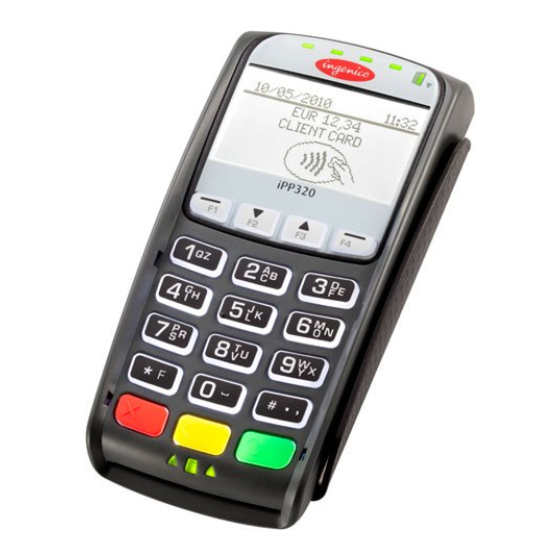
7_1_1 iPP320 and iPP350 Overview This section provides a quick reference for the iPP320 and iPP350 terminals. These terminals are functionally identical with the exception of the graphical display type. Both terminals feature a contactless card reader, smart card reader, and MSR as shown in the below image. -
Page 35: 7_1_2 Ipp320 And Ipp350 Power Requirements
7_1_2 iPP320 and iPP350 Power Requirements An external power supply is required when connecting the iPP320 or iPP350 to the Host via Ethernet and 5m length RS-232 cables. Ingenico specifies a DC power supply (model number 179901469) for this device. These terminals may also be powered from a POS via the USB (5V, 500mA) interface. -
Page 36: 7_1_4 Ipp320 And Ipp350 Host Interface Options
7_1_4 iPP320 and iPP350 Host Interface Options A master port which is located on the back of the device enables the iPP320 and iPP350 PIN pad devices to connect to the Host via the following interfaces: RS-232 Ethernet Refer to the below image for the interface port location on these devices. -
Page 37: 7_2_1 Isc250 Overview
When interfacing the iSC250 to the POS via RS-232, USB (5V), or Ethernet interfaces, an Ingenico power supply (192011597) is required. Power may also be provided by the POS via USB (12V or 24V) or RS-485 (via Multipoint) connections. If an Ingenico power supply was provided with the terminal, plug the power supply connector into the jack on the Multipoint cable. -
Page 38: 7_2_3 Isc250 Sam And Micro Sd Card Slots
Before you disconnect the terminal from the POS, you must first disconnect power in order to prevent damage to the terminal. 7_2_3 iSC250 SAM and Micro SD Card Slots There are two Secure Access Module (SAM) slots and two Micro SD slots which are accessible via an access door which is located on the bottom of the terminal. -
Page 39: 7_2_4 Isc250 Contactless Module
7_2_4 iSC250 Contactless Module The contactless module is accessible via the access door on the bottom of the device. Refer to the below image which shows the location and removal of the contactless module. 7_2_5 iSC250 Peripheral Connectors and Host Interface Options The iSC250 may interface to a Host system using any of the following interface options: RS-232 Tailgate (RS-485) -
Page 40: 7_2_6 Isc250 Multipoint Connector
7_2_6 iSC250 Multipoint Connector The Multipoint connector located on the bottom of the terminal may be attached with screws for additional security. This connector is used to connect RS-232, Tailgate (RS-485), USB, Ethernet, Magic box or Universal cables. It is important that you are using the correct cable for the required interface. -
Page 41: 7_3 Isc350 Quick Reference
Place the iSC250 in front of you with the bottom of the terminal facing up. Be careful not to place the device on a surface where the display screen can be scratched or damaged. If you have secured the cable with screws, carefully remove the two screws from either side of the Multipoint cable. Carefully pull out the Multipoint cable using the loop as shown in the below image. -
Page 42: 7_3_2 Isc350 Power Requirements
7_3_2 iSC350 Power Requirements The iSC350 can receive power from the POS system or via an external power supply provided by Ingenico. When interfacing to the POS via RS-232, USB (5V), or Ethernet interfaces, a separate Ingenico power supply (192008227) is required. Power may also be provided by the POS via USB (12V or 24V) or RS-485 (via Multipoint) connections. -
Page 43: 7_3_4 Isc350 Peripheral Connectors And Host Interface Options
7_3_4 iSC350 Peripheral Connectors and Host Interface Options The iSC350 PIN pad device may interface with a Host system using any of the following options: RS-232 Tailgate (RS-485) Ethernet Interface ports and peripheral connections are located on a panel at the back of the device. Peripheral connectors on this panel include: VGA connection Audio output... -
Page 44: 7_4 Isc480 Quick Reference
Depending on device configuration, a USB port and audio output connection are available on the side ports as shown in the below image. A cable retention bar secures cables to the terminal in order to prevent cables from becoming loose or damaged. When servicing cables, this bar must be removed and then properly reinstalled when servicing is completed. -
Page 45: 7_4_1 Isc480 Overview
7_4_2 iSC480 Power Requirements A separate Ingenico DC power supply (192006210 and power cord 188413214) is required when connecting the iSC480 device via RS232, USB (5V), and Ethernet. When the device is powered from a POS, power may be provided via a USB (12V or 24V) or RS485 cable. -
Page 46: 7_4_3 Isc480 Sam And Micro Sd Card Slots
7_4_3 iSC480 SAM and Micro SD Card Slots The iSC480 features two Secure Access Module (SAM) slots to hold full size SAM cards. These cards store proprietary information for use with smart cardbased applications. Refer to the below image for the location of the SAM access door. 7_4_4 iSC480 Peripheral Connectors and Host Interface Ports The iSC480 PIN pad device may interface with the Host system via the following interface options: RS-232... -
Page 47: 7_5 Ismp Quick Reference
7_5 iSMP Quick Reference The iSMP Quick Reference is organized into the following sections: iSMP Overview iSMP Power Requirements iSMP SAM and Micro SD Card Slots iSMP Interface Options iSMP Barcode Reader 7_5_1 iSMP Overview This section provides a quick reference for the iSMP PIN pad device. The iSMP processes MSR, contactless, and EMV cards, and is Bluetooth compatible. -
Page 48: 7_5_2 Ismp Power Requirements
7_5_2 iSMP Power Requirements The iSMP may be charged through the cradle accessory, or via the Multi-plug micro-USB cable. The device features a 1200mAh battery which supports up to 800 card transactions and 66 hours in standby mode. 7_5_3 iSMP SAM and Micro SD Card Slots There are no provisions for Secure Access Modules in the iSMP. -
Page 49: 7_5_5 Ismp Barcode Reader
7_5_5 iSMP Barcode Reader The iSMP features a factory option 1D/2D barcode reader which supports all major standards. The barcode reader is located in the edge of the device as shown in the below image. 49/57 Telium Troubleshooting Guide / June 28, 2014... -
Page 50: 7_6 Ismp Companion Quick Reference
7_6 iSMP Companion Quick Reference The iSMP Companion Quick Reference is organized into the following sections: iSMP Companion Overview iSMP Companion Power Requirements iSMP Companion Interface Options iSMP Companion Barcode Reader 7_6_1 iSMP Companion Overview This section provides a quick reference for the iSMP Companion (iSMPc) PIN pad device. The iSMP Companion processes MSR, contactless, and EMV cards, and is Bluetooth compatible. -
Page 51: 7_6_4 Ismp Companion Barcode Reader
7_6_4 iSMP Companion Barcode Reader The iSMP Companion features an optional 1D/2D integrated barcode reader which supports all major standards. The barcode reader is located in the edge of the device as shown in the below image. 7_7 iWL250 Quick Reference The iWL250 Quick Reference is organized into the following sections: iWL250 Overview iWL250 Power Requirements... -
Page 52: 7_7_2 Iwl250 Power Requirements
7_7_2 iWL250 Power Requirements The iWL250 may be powered through the terminal base or through an optional terminal car charger. This device also features a 2050mAh batter for extended use independent of a power connection. Refer to the below image which shows the base and interface connections. -
Page 53: 7_7_4 Iwl250 Interface With Host System
7_7_4 iWL250 Interface with Host System In standalone mode the iWL250 may communicate to the Host system via a micro USB port, or via wireless (GPRS, 3G HSDPA, or Bluetooth). When connected with its base, communications options for the iWL250 include: Dial-up modem (currently not used with RBA and UIA applications) USB-A RS-232... -
Page 54: 7_8_1 Iup250 Overview
This section is organized as follows: iUP250 Overview iUP250 Power Requirements iUP250 SAM and SIM Options iUP250 Interface Options iUR250 Overview iUC150 Overview 7_8_1 iUP250 Overview The iUP250 is an iSelf series device which is integrated with external card readers to perform MSR, EMV, Hybrid, and contactless card transactions. -
Page 55: 7_8_2 Iup250 Power Requirements
7_8_2 iUP250 Power Requirements The iUP250 is powered by an external 12V-30V DC power supply. Both iUR250 and iUC150 card readers draw 5V power from the iUP250 via the USB. 7_8_3 iUP250 SAM and SIM Options The iUP250 features provisions for 2 Secure Access Modules and one optional SIM. There are also provisions for one micro SD card. 7_8_4 iUP250 Interface Options Host interface options for the iUP250 include: RS-232... -
Page 56: 7_8_6 Iuc150 Overview
7_8_6 iUC150 Overview The iUC150 integrates with the iUP250 as a contactless card reader. The iUC150 also complies with the following standards: MasterCard PayPass VISA PayWave EMV contactless e-wallet Communications with the iUP250 and power are provided through a USB interface. The iUC150 also features an RS-232 interface. Refer to the below image of the iUC150. -
Page 57: 8_Revision History
8_Revision History Changes Manual Application Revision Revision Rev 2 Reformatted Telium Manager, TDA, and TSA menu option illustrations. Edited General Troubleshooting tables. Removed flowcharts from document. Incorporated new devices to document and added Quick references for: iSc480 iSMP iSMP Companion iWL250 iUP250 iUR250...
Need help?
Do you have a question about the iPP320 and is the answer not in the manual?
Questions and answers