ingenico iPP300 / iPP320 / iPP350 Installation and Quick Reference Guide
- Installation manual ,
- Troubleshooting manual (57 pages) ,
- Installation & usage (21 pages)
Advertisement
")
iPP320 (with PIN shield)
")
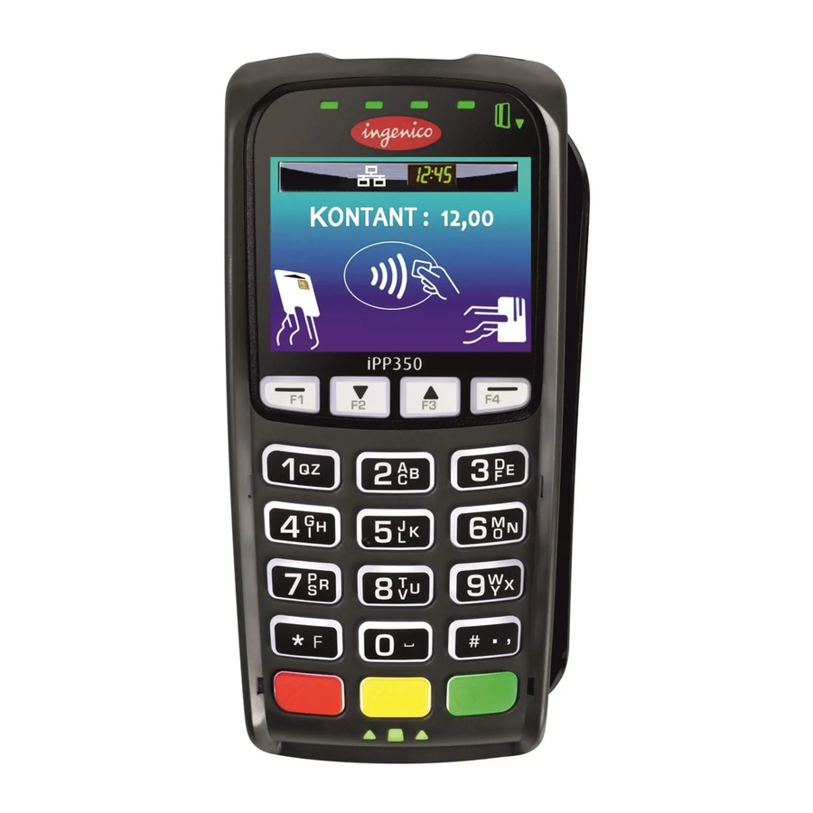
iPP350 (without PIN shield)
Introduction
Ingenico's iPP300 secure electronic payment devices include the iPP320 and the iPP350. Each device consists of the following:
- 2.7" graphical monochrome LCD display (iPP320)
- 2.7" TFT color QVGA display (iPP350)
- Bi-directional magnetic stripe reader
- Smart card reader
- ADA-friendly keypad
- PIN privacy shield (field-installable)
- Integrated contactless card reader. *
For details on these features, see the Specifications section in this document.
 For the contactless card reader function to work properly, no metallic adapter or hood should be used on or around the device and, particularly do not use a locally added metallic PIN privacy shield or mounting cradle. Using a metallic adapter on or near the device can severely degrade the contactless reader's performance. Metal can cause electromagnetic field interference which can negatively impact the contactless function.
Device Installation
The installation procedure includes:
- Selecting the device location
- Connecting the device
- Connecting an interface cable and power supply (if required)
- Attaching the PIN privacy shield (if desired)
Each step is described in the sections that follow.
Box Contents
Carefully inspect the carton and contents for any shipping damage. If the device is damaged, file a claim immediately with the shipping company and notify your device provider.
- Remove the contents from the box. You should have:
- iPP300 terminal
- This guide
- Connection cable or i3070 cable adapter
- Power supply (if required)
- PIN privacy shield (optional)
- 3 x m2.5 screws (optional)
- Application User Guide (optional)
- Save the carton and packing material for repackaging or moving/shipping the device in the future.
Selecting the Device Location
The iPP300 may be mounted on a flat surface or customer stand (recommended). Ingenico recommends physically securing the device to avoid theft. For additional anti-theft security, attach a Kensington Locking cable (or similar device) to the key lock slot on the left side of the device.
Power may be provided from a host Point of Sale (POS) system or from an Ingenico power supply. If using an Ingenico power supply, the device must be placed close to an easily-accessible power outlet.
Do not place the iPP300 on a PC monitor, adjacent to an electronically active security tag deactivation system, or near other sources of magnetic fields.
The iPP300 must be at least 12 inches away from an electronically active type of security tag deactivation pad. There are two types of security tag deactivation systems:
- An electronically active system sends out a powerful and potentially disruptive signal to deactivate a security tag. If the iPP300 is placed too close to the system's pad, or placed above the pad, malfunctions may occur.
- A passive system is a permanent magnet type that does not send out a signal. This type does not affect the iPP300.
Connecting the Terminal
Do not connect power to the iPP300 device until instructed to do so.
Use the provided cable or cable adapter to connect your device. If using an i3070 cable adapter, existing i3070 communication cables can be used.
- Place the iPP300 device in front of you with the bottom of the unit facing up. Be careful not to place the device on a surface where the device can be scratched or damaged.
- Pull the cable's retraction handle up on the device's HDMI connector end of the cable as shown in figure 1 below.
- Place the cable connector in the port and push firmly in place.

Figure 1: Cable Placed in iPP300 Port
- If desired, use two of the supplied m2.5 screws to secure cable to the base of the iPP300.
- Push the handle on the cable down to secure the cable in place.
- Connect the other end of the cable into the POS or PC as appropriate
- Remove the protective film from the graphical display screen.

The use of screws is optional. When using the iPP300 without a contactless card reader* or SAMs, there are no screw related operational security issues.
Cables and power supply
Refer to your equipment provider or Ingenico representative for details of appropriate cables and power supplies available. Only Ingenico recommended cables may be used. Use of non Ingenico accessories may result in damage and void any warranty.
| Connection Type | Description |
| Ethernet | 8-pin RJ45. Use to connect Ethernet 10/100 BASE-T. |
| USB | USB 2.0 Host high speed. 5V, 500mA max. Supports peripheral USB devices. |
| RS-232 | 9-pin MiniDIN9 port. Use for RS-232 and USB 2.0 full speed connections. |
| Power Supply | Some cables have a power supply input plug at the host end of the cable (the end furthest away from the iPP300). Do not plug in the Power Supply until you are instructed to do so. |
To avoid accidental damage, secure cables and power cords.
Connecting a Power Supply
Use only an Ingenico-provided power supply where a separate DC power supply is required. If the device is powered directly from a POS, power may be provided via the USB port (power through the USB 2.0 port is rated at 5V, 500mA). Use of non-Ingenico power supplies may result in damage. Damage of this type is not covered by warranty.
Connect the cable to the iPP300's port before connecting the device to power. Only use the power supply provided by Ingenico.
- If your device came with a power supply, plug the power supply connector into the jack on the interface cable as shown in figure 2 below.

Figure 2: Sample Cable Conversion
- Plug the power supply into a power outlet. The iPP300 will self-initialize when power is applied.

Attaching the PIN Privacy Shield (Optional)
A PIN privacy shield may be provided for optional use. To attach the PIN privacy shield, do the following:
- Remove the protective tabs from the double sided adhesive tape pads on the PIN shield.
- Align the hooked ends of the PIN privacy shield into the slots on the outside bottom edges of the keypad (near the red [Cancel] key and the green [Enter] key).
- Push the PIN privacy shield down onto the device to secure it. The device can be used immediately, but avoid undue strain on the PIN shield for 24hrs to allow the adhesive tape to fully cure for a strong and permanent grip.
| Part # | Description |
| 296 111 328 | PIN privacy shield (optional) |
Operations
Powering On
After you apply power to the iPP300 device, the device is ready for use. The iPP300 device may be left on indefinitely, or may be disconnected from power as necessary.
Restarting the Device
To restart the terminal, press the yellow [Clear] key and [#.,] simultaneously. Alternatively, disconnect and reconnect the device's power source.
Using a Magnetic Stripe Card
The iPP300 device's magnetic stripe reader reads debit, credit, and all standard magnetic stripe cards. When the application prompts for a magnetic stripe card, the magnetic stripe logo on the top upper right side of the device illuminates. Be sure the magnetic stripe side of the card is facing toward the iPP300 graphical display screen. Slide the card in either direction. For best results, slide the card in a continuous motion.

Using a Smart Card
When the application prompts the cardholder for a smart card, the smart card logos will illuminate. Insert the smart card into the slot on the front of the device with the chip facing up and towards the slot. Green lights located on top of the smart card reader slot, under software control, can prompt the cardholder when to insert or remove a card.
It is necessary for the card to remain in the reader slot until the application indicates that it can be removed.
If PIN entry is required, the keypad can also be programmed to illuminate under application control.

Using a Contactless Card
The iPP300 contactless card reader reads contactless payment cards. When prompted, hold the contactless payment card close to the active zone around the display. A series of green lights illuminate on the top of the device when the contactless card has been read.

* Contactless reader capability is Optional on early PCIPTS V2 and V3 models.
Troubleshooting
Magnetic Card Reader Does Not Work Properly
- Slide the card through the magnetic stripe reader as described in Swiping a Magnetic Stripe Card.
- Swipe the card at a faster or slower steady speed.
- Swipe the card in a different direction.
- Inspect the magnetic stripe on the card to make sure it is not scratched or badly worn.
- To determine if there is a problem with the card:
- If your host device (POS) has a magnetic stripe reader, try swiping the card there.
- If you have another working iPP300 device, try swiping the card there.
- If there is still a problem, contact your Help Desk.
No Information Visible on Screen
- Make sure that the iPP300 cable connector is fully inserted into the back of the device.
- Restart the device (see Restarting the Device above).
- Unplug the device and examine the connector's pins. If there are any pins that are bent, or if other damage is visible, replace the cable or adapter.
- If you have another working iPP300 device, swap the devices to determine if the problem is with the device, cable, POS, PC, or power supply.
- Reset the host by turning it off and back on again.
Specifications
Processors: Main Processor: RISC 32-bit ARM9, 450 MIPS. Integrated Crypto Processor: RISC 32-bit ARM7, 50 MIPS.
Operating System (OS): Telium 2 with HTML GUI.
Display: iPP320: graphical monochrome LCD, resolution of 128 x 64. iPP350: graphical active 2.7" TFT color QVGA, resolution of 320 x 240 with 4096 colors.
Memory: 32 MB SDRAM, 128 MB Flash.
Keypad: 19 keys including four (4) function keys; raised markings, ADA-friendly. White backlit.
SAMs: 3 SAM slots.
Buzzer: 65 dB at 1 meter.
Communications: HOST port: RS-232, USB, Ethernet (TCP/IP).
Dimensions (without PIN privacy shield): 6.3" x 3.3" x 1.6" (168 mm x 83 mm x 41 mm)
Weight (without PIN privacy shield and cable): 9.5 oz. (269 g).
Face Plate Standard Color: Ingenico gray.
Magnetic Stripe Card Reader: Bi-directional magnetic stripe card reader, triple track. Magnetic Stripe logo illuminates.
Smart Card Reader: EMV L1 and L2 certified – meets EMV levels 1.0 - 4.0 specifications. Complies with IS 7816 - 1/2/3. Smart card icons illuminate.
Contactless: Integrated contactless card reader.
Supports ISO 18443 A/B, MIFARE Classic, MIFARE DESFire.
(* Please Note: Contactless reader capability is Optional on early PCIPTS V2 and V3 models. PCIPTS V4 approved models are supplied with contactless capability as a standard feature.)
Power: Powered through USB (rated at 5V, 500 mA). Unit can also be powered from a RS-232 or Ethernet cable with an appropriate power supply. Power via Ethernet is supported in selected models only. Contact your Ingenico representative for details on specific model numbers.
Safety: UL/CSA 60951-1
Security: PCI PTS 2.x and Interac (Canada).
RFID: IC and FCC: Part 15B and Part 15C.
Environmental Requirements
The device is designed to operate in the following environment:
- Operating temperature of 41°F to 113°F (+5°C to +45°C)
- Operating humidity of 85% RH (non-condensing) at 131°F (+55°C)
- Storage temperature of -4°F to 158°F (-20°C to +70°C)
- Storage humidity of 85% at 131°F (+55°C)
Any liquid spill on or around the device must be removed immediately.
More Information
For more information on cleaning, troubleshooting, operating the device, features, specifications, and accessories, please contact your equipment's supplier.
Security
Your device fulfills current applicable PCIPTS security requirements. Physical (antitheft) security can be enhanced by the use of a Kensington Locking cable (or similar device) attached to the key lock slot.
You are strongly advised to ensure that privileged access to your device is only granted to staff that have been independently verified as being trustworthy.
Security Assurance
Perform the following tasks daily to ensure the security and compliance of your device:
Checking the Device's Integrity
Ensure that no attempts have been made to tamper with the device, using the following method:
- Check the device and ensure that there is NO external damage, particularly around the keypad, display, and card reader areas.
- Ensure the keypad is firmly in place.
- Ensure that there are NO additional cables protruding from the device or associated equipment.
- Ensure that there are NO holes drilled into the device's housing.
Alert Irruption
- Your iPP300 device detects any tampered state.
- In this state the device will repeatedly flash the message "Alert Irruption!" and further use of the device will not be possible. If you observe the "Alert Irruption!" message, you should contact your helpdesk immediately.
Note on PCI PTS v4 iPP300 models
PCI PTS v4 security requirements stipulate that the terminal must reboot at least once every 24 hours. If the reboot is not initiated through the connected device within 24 hours, the terminal will automatically reboot. Please refer to the relevant application guide for further information.
Checking the Installation Site
- Ensure that there are NO security cameras focusing on the device.
- Ensure that there are NO objects nearby in which cameras could be hidden.
- Ensure that the device CANNOT be observed from outside (any window or door opening) during customer Pin entry.
NEVER ask the customer to divulge their PIN. Customers should be advised to ensure that they are not being observed when entering their PIN.
Lithium Battery
The IPP3X0 is fitted with a lithium battery which is not accessible to the user.
Customer Service
Only qualified Ingenico repair facilities may open the unit for any reason. To request an RMA for return and repair of a defective unit please e-mail the appropriate customer support department per below.
Customer Service – USA
Customerservice.us@ingenico.com
Customer Service-Canada
TCChelpdesk@Ingenico.com
Compliance
U.S. Federal Communications Commission Warning
FCC standard compliance marking certifies that the product stipulated here: IPP3X0XXXXXXX conforms to the following harmonized standards: part 15 subpart B of the FCC rules. This class (B) digital apparatus complies with Canadian ICES-003.
Changes or modifications not expressly approved by the party responsible for compliance could void the user's authority to operate the equipment.
NOTE: This equipment has been tested and found to comply with the limits for a Class B digital device, pursuant to Part 15 of the FCC Rules. These limits are designed to provide reasonable protection against harmful interference in a residential installation. This equipment generates, uses, and can radiate radio frequency energy and, if not installed and used in accordance with the instruction, may cause harmful interference to radio communications. However, there is no guarantee that interference will not occur in a particular installation. If this equipment does cause harmful interference to radio or television reception which can be determined by turning the equipment off and on, the user is encouraged to try to correct interference by one or more of the following measures:
- Reorient or relocate the receiving antenna
- Increase the separation between the equipment and receiver
- Connect the equipment to an outlet on a circuit different from that to which the receiver is connected
- Consult the dealer or an experienced radio/TV technician for help
Industry Canada Warning
Under Industry Canada regulations, this radio transmitter may only operate using an antenna of a type and maximum (or lesser) gain approved for the transmitter by Industry Canada. To reduce potential radio interference to other users, the antenna type and its gain should be so chosen that the equivalent isotropically radiated power (e.i.r.p.) is not more than that necessary for successful communication.
This device complies with Industry Canada license-exempt RSS standard(s). Operation is subject to the following two conditions: (1) this device may not cause interference, and (2) this device must accept any interference, including interference that may cause undesired operation of the device.
Ingenico Inc.
3025 Windward Plaza, Alpharetta, GA 30005.
Tel: +1.678.456.1200
Fax: +1.678.456.1201
www.ingenico.us
Ingenico Canada, Inc.
5180 Orbitor Drive, 2nd Floor, Mississauga, Ontario, L4W 5L9
Tel +1 905.212. 9ING
Fax: +1 905.212. 9155
http://www.ingenico.ca

Videosingenico iPP300 - Connecting Video
Documents / Resources
References
Download manual
Here you can download full pdf version of manual, it may contain additional safety instructions, warranty information, FCC rules, etc.
Download ingenico iPP300 / iPP320 / iPP350 Installation and Quick Reference Guide
Advertisement


Need help?
Do you have a question about the iPP320 and is the answer not in the manual?
Questions and answers