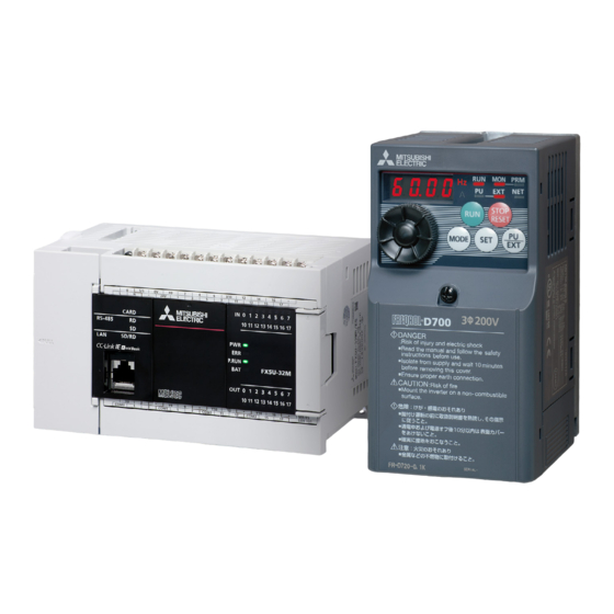
Mitsubishi Electric MELSEC iQ-F Series Quick Connection Manual
Programmable controller
Hide thumbs
Also See for MELSEC iQ-F Series:
- Programming manual (1472 pages) ,
- User manual (954 pages) ,
- Handbook (132 pages)


Need help?
Do you have a question about the MELSEC iQ-F Series and is the answer not in the manual?
Questions and answers