Mitsubishi Electric MELSEC iQ-F Series Quick Connection Manual
Hide thumbs
Also See for MELSEC iQ-F Series:
- Programming manual (1472 pages) ,
- User manual (954 pages) ,
- Handbook (132 pages)
Table of Contents
Advertisement
Quick Links
FACTORY AUTOMATION
Mitsubishi Electric Programmable Controller
Mitsubishi Electric Programmable Controller
MELSEC iQ-F Series
MELSEC iQ-F Series
Predefined Protocol Support
Predefined Protocol Support
Predefined Protocol Support
For Positioning Function Block Library
For Positioning Function Block Library
For Positioning Function Block Library
Quick Connection Guide
Quick Connection Guide
Quick Connection Guide
(IAI Corporation)
(IAI Corporation)
(IAI Corporation)
Advertisement
Table of Contents

Related Manuals for Mitsubishi Electric MELSEC iQ-F Series


Summary of Contents for Mitsubishi Electric MELSEC iQ-F Series
- Page 1 FACTORY AUTOMATION Mitsubishi Electric Programmable Controller Mitsubishi Electric Programmable Controller MELSEC iQ-F Series MELSEC iQ-F Series Quick Connection Guide Quick Connection Guide Quick Connection Guide Predefined Protocol Support Predefined Protocol Support Predefined Protocol Support For Positioning Function Block Library For Positioning Function Block Library...
-
Page 2: Introduction
INTRODUCTION Thank you for purchasing the MELSEC iQ-F series. This manual describes Predefined Protocol Support Tool For Positioning and FBs for Predefined Protocol Support for Positioning, which enable positioning operation of the IAI ROBO Cylinder easier than before. Positioning operation is performed by connecting the FX5U CPU module or FX5UC CPU module and the IAI controller. - Page 3 If in doubt about the operation or use, please contact your local Mitsubishi Electric representative. • Mitsubishi Electric will not accept responsibility for actual use of the product based on these illustrative examples. Please use it after confirming the function and safety of the equipment and system.
-
Page 4: Table Of Contents
CONTENTS INTRODUCTION ................1 RELEVANT MANUALS . -
Page 5: Relevant Manuals
RELEVANT MANUALS The following relevant manuals can be downloaded from the Mitsubishi Electric FA site. www.mitsubishielectric.co.jp/fa/ref/ref.html?kisyu=plcf&manual=download_all [: Available, : Not available] Manual name Available form <manual number> e-Manual MELSEC iQ-F FX5S/FX5UJ/FX5U/FX5UC User's Manual (Hardware) <SH-082452ENG> MELSEC iQ-F FX5 User's Manual (Application) <JY997D55401>... -
Page 6: Key Features
24VDC power supply 24VDC power supply *1 FB libraries can be downloaded for free from the Mitsubishi Electric FA website. www.mitsubishielectric.co.jp/fa/ref/ref.html?kisyu=plcf&samplelibrary=download_all Easy settings with Predefined Protocol Support Tool For Positioning Writing positioning data and wiring were required for each controller. - Page 7 Reduced debugging time thanks to no need for a program The status of positioning control, alarms occurred, and other information can be checked in a window of Predefined Protocol Support Tool For Positioning without a dedicated HMI (Human Machine Interface) or a program. Therefore, debugging efficiency is dramatically improved.
-
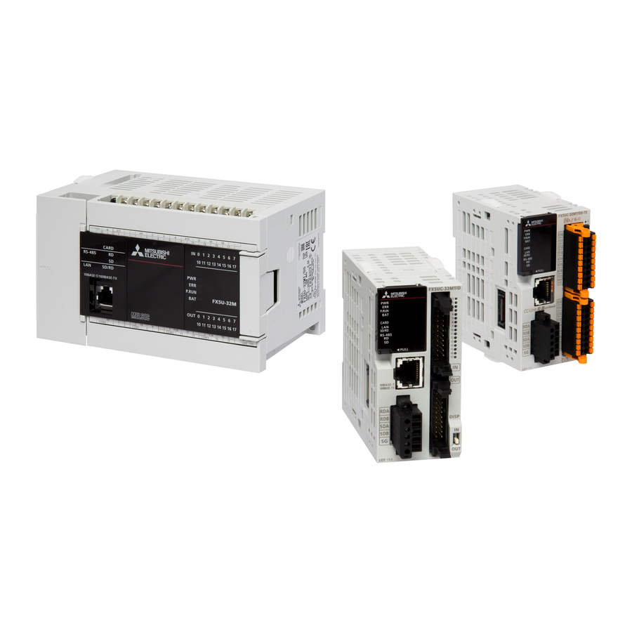
Page 8: Chapter 1 Applicable Models
APPLICABLE MODELS The following models can be used for a series of operations described in this manual. Programmable controller IAI controller FX5U CPU module FX5UC CPU module The model shown in the figure is of the PCON-CB/ CGB/CBP/CGBP type. ■PCON series C/CA/CB/CFA/CFB/CF/CY/CYB/SE ■ACON series C/CA/CB/CY/CYB/SE... - Page 9 MEMO 1 APPLICABLE MODELS...
-
Page 10: Chapter 2 Preparation
PREPARATION System Configuration This section describes the system configuration in which two IAI controllers are connected to one programmable controller. Predefined Protocol Predefined Protocol Support Tool For Support Tool For Positioning Positioning Personal computer FX5U CPU module Ethernet Install GX Works3 in advance. Serial communication (MODBUS RTU) Controller ... -
Page 11: Required Products
485ADP), settings different from the parameter settings described in this manual are required. Refer to the following for details. MELSEC iQ-F FX5 User's Manual (Serial Communication), Section 7.5 Communication Settings *2 To obtain the latest version, please contact your local Mitsubishi Electric representative. 24VDC power supply... -
Page 12: Wiring
Software GX Works3 must import the following. Item File name Reference FB library PositioningSupportIAI_F.mslm Page 17 PROGRAMMABLE CONTROLLER SETTINGS Wiring Wiring an IAI controller This section shows how to wire an IAI controller. Wiring the power connector Wire the power connector. Emergency stop switch +24V... - Page 13 ■Installing cables Treat the sheath of the cable as follows. • Stripped wire length: 10mm Insert a cable whose end has been processed fully into the insertion slot. If the wire cannot be inserted by this method, insert the wire fully while pressing the orange retaining pin using a screwdriver with a 2.0mm to 2.5mm wide flat blade.
-
Page 14: Wiring The Programmable Controller
Wiring the programmable controller For the power supply wiring of the programmable controller, refer to the following. MELSEC iQ-F FX5S/FX5UJ/FX5U/FX5UC User's Manual (Hardware), Section 13.4 Power Supply Wiring Set the terminating resistor by using the programmable controller. Set 110 with the termination resistor selector switch of the programmable controller. -
Page 15: Operation Flow Diagram
Operation Flow Diagram Preparing the required products Setting the IAI controllers (wiring) Predefined Protocol Support Tool For Positioning Setting the programmable controller Checking the communication status GX Works3 Program examples and checking the operation When X24 is OFF, the instruction code H0FB is sent at the rising edge of X25 and the operation mode is changed to 2 (PU mode). H0FB D280 Operation... -
Page 16: Chapter 3 Iai Controller Settings
IAI CONTROLLER SETTINGS Part Names This section shows the part names of an IAI controller (PCON-CB). Name Description Controller status LED Shows the operating status of the controller. SV on (green): Servo ON SV flashing (green): Automatic Servo OFF ALM on (red): Alarm (operation release level or higher), motor driving power supply OFF, emergency stop Both SV and ALM on (orange): Initialization at power-on in progress Off: Control power supply OFF, Servo OFF PIO connector/Field network... -
Page 17: Setting Switches
Name Description Power connector Connector for supplying each type of power (controller control power, Robo Cylinder power, brake control power) and inputting emergency stop status signals. *1 For normal operation, make sure to set the brake release switch to the NOM side. (Set the switch to the BK RLS side only when necessary, such as adjustment at start-up.) If the switch remains set to the BK RLS side, even when the Servo OFF state arises, the brakes do not activate. -
Page 18: Chapter 4 Programmable Controller Settings
PROGRAMMABLE CONTROLLER SETTINGS Part Names For the part names of the programmable controller, refer to the following. MELSEC iQ-F FX5S/FX5UJ/FX5U/FX5UC User's Manual (Hardware), Chapter 3 PART NAMES 4 PROGRAMMABLE CONTROLLER SETTINGS 4.1 Part Names... -
Page 19: Parameter Settings
Parameter Settings This section describes how to set parameters required for the programmable controller using GX Works3 and Predefined Protocol Support Tool For Positioning. GX Works3 parameter settings This section describes how to set parameters required for the programmable controller using GX Works3. Connect the personal computer and the programmable controller with an Ethernet cable. - Page 20 In "Communication Protocol Type", select "Predefined Protocol Support Function". When the confirmation window appears, click the [Yes] button. 4 PROGRAMMABLE CONTROLLER SETTINGS 4.2 Parameter Settings...
- Page 21 Set "Advanced Settings" as follows, and click the [Apply] button. Item Setting value Data Length 8 (Default value: 7) Parity Bit None (Default value: Odd) Stop Bit 1bit (Default value: 1bit) Baud Rate 38400bps (Default value: 115200bps) For the settings in "Advanced Settings" except "Baud Rate", be sure to set the above values. 4 PROGRAMMABLE CONTROLLER SETTINGS 4.2 Parameter Settings...
- Page 22 Parameter settings of Predefined Protocol Support Tool For Positioning This section describes how to set parameters required for the programmable controller using Predefined Protocol Support Tool For Positioning. Select [Tool] [Module Tool List] from the menu of GX Works3. For "Module Series Selection"...
- Page 23 The "Predefined Protocol Support Tool For Positioning" window opens. Select [Project] on the toolbar [New]. Select "IAI" under "Select Manufacturer", select the checkbox of "CH1" under "The channel to be used", then click the [OK] button. The channel used is determined as follows. •...
- Page 24 Configure settings as shown in the following window, and click the [Apply] button. To save the protocol setting data, select [Project] [Save As], and save it using any name. Select [Project] [Exit] to close the window. Precautions The following devices are used to write predefined protocol information. Make sure not to overlap with the devices used for other controls.
-
Page 25: Communication Test For The Programmable Controller
Communication Test for the Programmable Controller Directly connect the Ethernet ports as shown below. FX5U CPU module Ethernet Select [Online] [Current Connection Destination]. Select "Direct Coupled Setting". 4 PROGRAMMABLE CONTROLLER SETTINGS 4.3 Communication Test for the Programmable Controller... - Page 26 Specify an Ethernet adapter of the personal computer which is used when the personal computer is directly connected to the CPU module. When "Not Specified" is set, select an adapter to be used from the drop-down list. After the adapter is selected, click the [Communication Test] button. For the connection via a hub, refer to the following.
-
Page 27: Writing Data To The Programmable Controller
Writing Data to the Programmable Controller This section describes how to write each parameter setting and program to the programmable controller. For details on programs, refer to the following. Page 33 PROGRAM EXAMPLE Writing GX Works3 parameter settings Perform the operation to determine the programs and the parameters before writing them to the programmable controller. - Page 28 Click "Parameter + Program", and click [Execute]. When the following window appears, click [Yes to all]. After the writing is complete, reset or power off and on the programmable controller. 4 PROGRAMMABLE CONTROLLER SETTINGS 4.4 Writing Data to the Programmable Controller...
- Page 29 Writing the parameter settings of Predefined Protocol Support Tool For Positioning Write protocol setting data to the CPU module. Select [Online] on the toolbar [Write the Predefined Protocol Information]. Select "CPU built-in memory" under "Target memory", and click the [Execute] button. Reset or power off and on the programmable controller to reflect the settings.
-
Page 30: Positioning Test
Positioning Test After the writing process, perform a test for communication with the IAI controllers. Predefined Protocol Support Tool For Positioning In the menu bar of "Predefined Protocol Support Tool For Positioning", select [Debug] [Positioning Test]. Select a channel number and an axis number for the test target in the "Select test target" window, and click the [OK] button. - Page 31 To change the test target, use the [Test Target Selection] button. When the [Modbus Command Enable] button is displayed, click the button. When the [Servo ON] button is displayed, click the button. Click the [Home Position Return] button. 4 PROGRAMMABLE CONTROLLER SETTINGS 4.5 Positioning Test...
- Page 32 When the preparation is completed, both lamps of "Servo" and "Home position" are ON in the monitor area. Positioning start Specify a number and execute positioning data. Select the [Positioning start] tab. Enter a positioning data number to be executed in "Positioning Data No.". Click the [Start] button.
- Page 33 JOG/Inching Set the speed or movement amount, and move the current position of the axis. Select the [JOG/Inching] tab, then click the [JOG/Inching Setting] button. Enter the JOG operation speed or the amount of movement at inching operation in the "JOG/Inching setting" window. Item Description JOG speed...
-
Page 34: Chapter 5 Program Example
PROGRAM EXAMPLE Operation The following shows an example of using this FB library for configuring the position table setting and performing the home position return and positioning operation for the IAI controller. The following FBs are used in this example. •... - Page 35 Overview of program example Perform monitoring to check the status of the IAI controller. Then, write the position table information to the position table No.0 of axis 1 and the position table No.0 of axis 2 of the IAI controller with the following settings. After writing information, perform a home position return, and move the ROBO Cylinder to the position which is 100mm away from the home position.
-
Page 36: Fb Library
FB Library Downloading the FB library In this manual, the Predefined Protocol Support for Positioning Function Block Reference (for IAI) is used. To obtain the FB library, please contact your local Mitsubishi Electric representative. 5 PROGRAM EXAMPLE 5.2 FB Library... -
Page 37: Importing The Fb Library
Importing the FB library This section describes how to register the obtained FB library to GX Works3. Decompress the FB library folder (zip file) before registering the FB library. Start GX Works3, and select [Project] on the toolbar [New]. In this manual, the following settings are used. - Page 38 Select the "PositioningSupportIAI_F.mslm" file in the decompressed FB library folder, and click [Open]. The selected file is added to [Library] in the "Element Selection" window. If the "Element Selection" window is not displayed, select [View] on the toolbar [Docking Window] [Element Selection] to open the window.
-
Page 39: How To Use The Fb Library
How to use the FB library Select an FB registered in the library from the "Element Selection" window, and drag and drop it to the program editor. Create an input ladder and an output ladder of the pasted FB to create a program. Arrange the FB input ladder to the left side, and output ladder to the right side of the window in the same manner as standard ladder programs. - Page 40 Insert a contact and input to B:i_bEN. Insert an FB Word device input to the left side of the FB. Insert an FB Word device output to the right side of the FB. Repeat these steps to create the ladder. 5 PROGRAM EXAMPLE 5.2 FB Library...
-
Page 41: Program Details
Program Details When using e-Manual Viewer, the program copy function is available to perform programming. For details, refer to the following. Page 57 How to Use the Program Copy Function of e-Manual Target channel setting Sets the target channel to 1 Target axis setting Sets the target axes to 1 and 2 Position table No. - Page 42 IAI controller monitoring By turning on i_bEN (Execution command), the status of the IAI controller is monitored by M+IAIMonitoring_F (Operation monitoring). When o_bMonitorOK (Monitoring status) is on, the monitoring table information of the IAI controller is stored in o_stMonitoringTable (Monitoring table). For details on how to access stLabel4 and stLabel5, which are local labels of the structure type (stMonitoringTable), refer to the following.
- Page 43 ■Redefining local labels When the above program examples are copied and pasted, the function blocks and local labels stLabel4 and stLabel5 become undefined. For details on how to redefine function blocks, refer to the following. Page 57 How to Use the Program Copy Function of e-Manual The method for redefining local labels stLabel4 and stLabel5 is explained in the following.
- Page 44 Select the [Navigation] window "Program" "Scan" "MAIN" "ProgPou" "Local Label", and check that local label stLabel4 is defined. Define local label stLabel5 in the same way. 5 PROGRAM EXAMPLE 5.3 Program Details...
- Page 45 Position table (input label) setting The following shows an example of setting the input labels for axes 1 and 2 of M+IAISetPositioningTable_F (Position table setting) by turning on M19 and M119. Sets the target position to 10000 Sets the positioning width to 100 Sets the speed to 10 Sets the individual zone boundary plus side to 0...
- Page 46 Setting the position table By turning on i_bEN (Execution command), the information on the positioning operation is set in the positioning table of the target axis by M+IAISetPositioningTable_F (Position table setting). Target channel: 1 Target axis: 1 Position table No.: 0 Target position: 10000 Positioning width: 100 Speed: 10...
- Page 47 Target channel:1 Target axis: 2 Position table No.: 0 Target position: 10000 Positioning width: 100 Speed: 10 Individual zone boundary plus side: 0 Individual zone boundary minus side: 0 Acceleration: 1 Deceleration: 1 Current limit value when pushed: 0033H Load current threshold value: 0 The positioning table can be configured by using Predefined Protocol Support Tool For Positioning as well.
- Page 48 Performing the home position return By turning on i_bEN (Execution command), the home position return is performed by M+IAIStartHomePositioning_F (Home position return). When the home position return is performed, the servo is automatically turned on. Target channel:1 Target axis: 1 Target channel:1 Target axis:2 5 PROGRAM EXAMPLE 5.3 Program Details...
- Page 49 Performing the positioning operation By turning on i_bEN (Execution command), the positioning operation of the set position table No. is performed by M+IAIStartPositioning_F (Positioning operation). When the positioning operation is performed, the servo is automatically turned on. Target channel:1 Target axis: 1 Position table No.: 0 Target channel:1 Target axis: 2 Position table No.: 0...
- Page 50 Servo OFF When performing maintenance of the target axis, turn off the servo by M+IAIServoControl_F (Servo ON/OFF). After normal completion, turn off i_bEN (Execution command). Target channel:1 Target axis: 1 Target channel:1 Target axis: 2 5 PROGRAM EXAMPLE 5.3 Program Details...
- Page 51 Acquiring the alarm that has occurred in the IAI controller If the 203H error occurs in the home position return or positioning operation, an alarm has occurred in the IAI controller. The following shows an example of storing the data in the local labels stLabel4 and stLabel5 of the structure type (stMonitoringTable) in the data register (D) by turning on M60 and M160.
- Page 52 Stores the alarm detail code in D160 Stores the alarm address in D161 Stores the alarm code in D162 Stores the alarm occurrence time in D163 Stores the current position monitor in D165 Stores the currently occurring alarm code in D167 Stores the input port in D168 Stores the output port in D169 Stores the device status 1 in D170...
- Page 53 Resetting the alarm that has occurred in the IAI controller When an alarm code is stored in D62 or D162, the alarm that has occurred in the IAI controller is reset by M+IAIMonitoring_F (Operation monitor) by turning on i_bAlmReset (Alarm reset). Target channel: 1 Target axis: 1 Target channel:1...
-
Page 54: Chapter 6 Troubleshooting
TROUBLESHOOTING Checking Procedure This section describes how to check the status of the programmable controller and the IAI controller. Checking the LED status Check the communication status with the LEDs of the programmable controller and IAI controller. Item Reference Programmable controller Page 54 Checking the LED status IAI controller Page 55 Checking the LED status... -
Page 55: Checking The Programmable Controller
Checking the Programmable Controller Checking the LED status Check the programmable controller status with the LED. Normal communications: Flashes at high speed. Faulty communications: ON (Flicks at regular interval.) Disconnection of Ethernet cable of the programmable controller: OFF Checking the error details On the toolbar of GX Works3, select [Diagnostics] ... -
Page 56: Checking The Iai Controller
Checking the IAI Controller Checking the LED status Check the LED status of the IAI controller. Controller status display LED For the LED indications of the IAI controller, refer to the following. Page 15 Part Names For details on error codes, refer to the following. Manual for the IAI controller being used 6 TROUBLESHOOTING 6.3 Checking the IAI Controller... -
Page 57: Appendix
APPENDIX Appendix 1 List of FBs for Predefined Protocol Support for Positioning The following table lists the FBs included in the FB library for Predefined Protocol Support for Positioning. Programs are created by combining FBs according to each application. Name Description M+IAIStartHomePositioning_F Executes the home position return. -
Page 58: Appendix 2 How To Use The Program Copy Function Of E-Manual
Appendix 2 How to Use the Program Copy Function of e-Manual Program examples in e-Manual can be copied and pasted to GX Works3. Click "Copy Ladder Program (for GX Works3)" in e-Manual. Right-click the mouse on the ladder editor of GX Works3, and select [Paste]. The copied program is pasted in undefined state. - Page 59 Click the [OK] button on the "FB Instance Name" window. When the FB is properly defined, the FB instance name is highlighted in gray. Label items (label name, data type, and others) are copied in the order defined as an example in this manual. Therefore, define label items in the same order as shown on the label editor of the engineering tool.
-
Page 60: Appendix 3 Got2000 Series Connection Sample Windows
The applicable models are as follows. • PCON series • ACON series • SCON series For information on sample windows for connecting GOT2000 and each controller, please contact your local Mitsubishi Electric representative. APPX Appendix 3 GOT2000 Series Connection Sample Windows... - Page 61 MEMO APPX Appendix 3 GOT2000 Series Connection Sample Windows...
-
Page 62: Revisions
First edition This manual confers no industrial property rights or any rights of any other kind, nor does it confer any patent licenses. Mitsubishi Electric Corporation cannot be held responsible for any problems involving industrial property rights which may occur as a result of using the contents noted in this manual. -
Page 63: Warranty
• Before using the product for special purposes such as nuclear power, electric power, aerospace, medicine or passenger movement vehicles, please contact Mitsubishi Electric sales office. • The product has been manufactured under strict quality control. However, when installing the product where major accidents or losses could occur if the product fails, install appropriate backup or failsafe functions into the system. - Page 64 MITSUBISHI ELECTRIC EUROPE B.V. French Branch Tel : +33-1-55-68-55-68 25, Boulevard des Bouvets, 92741 Nanterre Cedex, France Fax : +33-1-55-68-57-57 Czech Republic MITSUBISHI ELECTRIC EUROPE B.V. Czech Branch, Prague Office Tel : +420-255-719-200 Pekarska 621/7, 155 00 Praha 5, Czech Republic Poland MITSUBISHI ELECTRIC EUROPE B.V.
Need help?
Do you have a question about the MELSEC iQ-F Series and is the answer not in the manual?
Questions and answers