RGBlink GX4 User Manual
Hide thumbs
Also See for GX4:
- User manual (76 pages) ,
- Quick start manual (20 pages) ,
- Quick start manual (32 pages)
Table of Contents
Advertisement
Quick Links
Advertisement
Table of Contents

Related Manuals for RGBlink GX4


Summary of Contents for RGBlink GX4
- Page 1 USER MANUAL :RGB-RD-UM-GX4 E001 Article No V1.3 Revision No:...
-
Page 2: Table Of Contents
CONTENT Declarations..............................4 FCC/Warranty............................4 Operators Safety Summary........................5 Installation Safety Summary......................5 Chapter 1 Your Product..........................7 1.1 In the Box............................7 1.2 Product Overview.......................... 8 1.2.1 Rear Panel.......................... 9 1.2.2 Front Panel........................10 1.2.3 Dimension......................... 12 Chapter 2 Install Your Product.........................13 2.1 Plug in Signals..........................13 2.2 Plug in Main Power........................ - Page 3 6.3 Terms & Definitions........................38 6.4 Revison History..........................44 User Manual...
-
Page 4: Declarations
RGBlink. If the purchaser or a third party carries out modifications or repairs on goods delivered by RGBlink, or if the goods are handled incorrectly, in particular if the systems are commissioned operated incorrectly or if, after the transfer of risks, the goods are subject to influences not agreed upon in the contract, all guarantee claims of the purchaser will be rendered invalid. -
Page 5: Operators Safety Summary
Installation Safety Summary Safety Precautions For all GX4 processor installation procedures, please observe the following important safety and handling rules to avoid damage to yourself and the equipment. To protect users from electric shock, ensure that the chassis connects to earth via the ground wire provided in the AC power Cord. - Page 6 Before opening GX4 processor shipping box, inspect it for damage. If you find any damage, notify the shipping carrier immediately for all claims adjustments. As you open the box, compare its contents against the packing slip. If you find any shortages, contact your sales representative.
-
Page 7: Chapter 1 Your Product
Chapter 1 Your Product 1.1 In the Box AC Power Cord DVI to HDMI Cord USB Cable Note: AC Power Cable supplied as standard according to destination market. User Manual... -
Page 8: Product Overview
GX4 can work as LED display controller when universal senders cards is installed. There are 2 empty slots fitting for one 2.6mega pixels sender card or two 1.3mega pixels sender cards. RGBlink dedicated sender card module Subito™... -
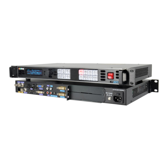
Page 9: Rear Panel
1.2.1 Rear Panel INPUT CONNECTORS OUTPUT CONNECTORS SDI in and SDI loop Audio Output 1 slot for optional single input DVI Output VGA input Slots preserved for sender cards CVBS Input CONTROL PORT HDMI In/Loop DVI input USB-A RS232 Audio input POWER Power switch Power IEC-3... -
Page 10: Front Panel
1.2.2 Front Panel OLED Display Displays current status of the product, and for feature selections provides interactive choices in conjunction with buttons on the front panel. Rotary Knob This knob used for menu selections and confirmation. turn to left and right to select menu item and push to confirm selection. Buttons This button used for menu selections Push the button again will return to the last level menu or exit the menu. - Page 11 CVBS input source selection and Number 5. SDI input source selection and Number 7. After optional input module is fitted, this button is to select the optional input source. Number 8. Short cut button of Audio Menu and Number 9 Short cut button of Black Out and Number 0.
-
Page 12: Dimension
1.2.3 Dimension Following is the dimension of GX4 for your reference:: Dimension:480mm×303mm×45mm User Manual... -
Page 13: Chapter 2 Install Your Product
Chapter 2 Install Your Product 2.1 Plug in Signals Connect signals to the product (ensure all devices are powered off first). Tighten connector screws/locks where provided. 2.2 Plug in Main Power Connect IEC cable to device and plug into wall socket. Turn on power at wall socket. 2.3 Turn on Your Product Turn the power switch on the rear to ON position. -
Page 14: Chapter 3 Use Your Product
Chapter 3 Use Your Product 3.1 Use the MENU Button Push【MENU】button to enter main menu. Turn the knob to select corresponding menu item. The symbol >indicate that the item is selected. Push the knob to confirm the operation. The symbol* means the selected item is under editing state, ready to be set or checked The operation diagram is as follows:... -
Page 15: Use The Menu
3.3 Use the Menu Use the menu system for convenient and intuitive operation. GX4 TST display shows the menu items. The TST display will show the default state when the menu is not in use, or the operation has timed out. Using the 【MENU】 button and rotary knob in the front panel, the TST display will show the corresponding menus according to user selections. - Page 16 HOR OFFSET: horizontal offset, -1-4095 CONNECT TYPE VER OFFSET: vertical offset,-1-4095 SAVE TO RECEIVER CARD CONNECT TYPE: the connection type of led cabinet. There are 8 types available . SAVE RECEIVER CARD: save setting above to receiver card. 1.3 RESET ALL CARD: reset all sender card and receiver card. 2.
-
Page 17: Input
Users can load LED configuration files from LED manufacturers to the GX4 devices by XTOOL. There are 15 manufacturers items in the sub-menu and each manufacture can store 16 files. 270 files in total allow to be loaded. 4. OUT BRIGHT Output brightness to adjust the brightness of LED screen, value ranging from 0-255 3.3.2 Input... - Page 18 8.DVI4In1 DVI 4 In 1) GX4 with optional DVI module installed comes with such signal types as VGA, DVI, CVBS, YPbPr. It is offered to users to choose the signal type through the DVI connector which is compatible with VGA, DVI, CVBS, YPbPr via adapter.
-
Page 19: Output
3.3.3 Output OUTPUT INFO >> OUTPUT FORMAT >> OUTPUT ADJUST >> SCREEN >> RATIO NORMAL TEXT OVERLAY >> DISPLAY MODE >> GAMMA LINEAR OUTPUT INFO : show current input information >1920x1080@60 DVI MODE DVI BITS 8 BIT COLOR SPACE IMAGE DE H POS DE V POS DE H SIZE... - Page 20 3. OUTPUT ADJUST DVI MODE BITS 8 BIT COLOR SPACE IMAGE DE ADJUST >> DVI MODE: DIV or HDMI BITS: DVI 8bit ,HDMI 8/10/12 bit COLOR SPACE: IMAGE or VIDEO DE ADJUST >DE H POS DE: ON or OFF V POS H SIZE 1920 H POS: horizontal position, value from 0 to 1920...
- Page 21 Note:Users can also set <SCREEN> by 【FS】 . Push FSbutton light on, Led display image in screen size, Push 【FS】again, button light off, Led display image in full size. RATIO : NORMAL, 16:9, 4:3 6. TEXT OVERLAY Text overlay function is to add subtitle on output image, more often used on such fields as live broadcasting, live concert, live commentary, and advertisement.
- Page 22 Select <PRESET>Push knoband turn the knob to “WhOnBk1”or “WhOnBk2” and Push knobagain Note:TEXT OVERLAY only support monochrome subtitles. >PRESET WhOnBk1 BLEND MODE MODE1 PRESET:User, WhONBk1 (white on black ) BLEND LEVEL WhONBk2 (white on black ),BkOnWh1(black on STAND ABOVE white),BkOnWh2(black on white), GrnOnBk1 (green on black),GrnOnBk2 (green on black), GrnOnWh1 (green on white)1 GrnOnWh2(green on white),RedOnBk1 (red on black), RedOnBk2 (red on black), RedOnWh1 (red on white),...
-
Page 23: Transition
GX4 can be used in multiple cascade mode to finish split. When do cascade, connect the signals to the signal distributor first, and then connect from the outputs of the signal distributor to each input of GX4. User can also do cascade via HDMI LOOP port. -
Page 24: System
>> HOT BACKUP >> DELAY RECALL 252S Sales Hotline 4008-592-114 After Sales Service 4008-592-315 Email:rgblinkcs@gmail.com Web: www.rgblink.com TEL +86(592)5771197 WORK TIME >> 3. WORK TIME TOTAL TIME >> BOOT TIMES WORK TIME: the consistent working time since Latest boot up. -
Page 25: Language
4. LOCK FRONT PANEL YES <OK>, NO <MENU> After the panel is locked, keep pressing MENU for 3 S to release the panel. 5. LICENSE SET UP ENETER PASSWORD 090721 and set new password for other users. 6. HOT BACKUP Hot Backup HOT BACKUP: ON or OFF Backup_1... -
Page 26: Shortcut Buttons
3.4 Shortcut Buttons GX4 comes with shortcut buttons to enter the sub-menu of certain features. Here are details of some quick buttons. 3.4.1【TAKE】Button When GX4 power on, system default HDMI input signal. To switch signal, press CVBS,VGA,DVI or SDI. For example, to switch to CVBS, push【VGA】... -
Page 27: Scale】Button
Save 1 used, overwrite SWAP IMAGE: Yes<OK>, NO <MENU> Select on or off to switch the main picture and secondary picture (the small one). ALPHA: Image transparency setting, the adjustment range is 0 to 16. SECLECT: Select IMAGE A or IMAGE B. 3.4.3【SCALE】Button To scale the output image, users can press 【SCALE】... -
Page 28: Load】Button
Pushknobto confirm,【MENU】to cancel. Up to 10 groups of SAVE can be done from SAVE1 to SAVE 10 3.4.5【LOAD】Button Push 【LOAD】LCD shows the instruction information to assist users complete LOAD operation. Meanwhile, among numeral buttons 0-9, some buttons lights are on, some flash and perhaps some lights go off. Buttons with light on indicate the <SAVE>... -
Page 29: Chapter 4 Ordering Codes
CHAPTER 4 ORDERING CODES 4.1 PRODUCT 820-1004-02-0 4.2 OPTIONS 4.2.1 Input Options 190-0001-04-2 Single DVI Input Module 190-0001-13-2 Single HDMI Input Module 790-0004-01-0 Single HDMI Input/Loop Module 190-0001-07-2 Single 3G SDI Input/Loop Moudle 190-0001-10-2 Single USB Input/Backup Module 190-0001-15-2 Single HDBaseT Input Module 790-1001-28-0 Subito Quatro Sender Module User Manual... -
Page 30: Chapter 5 Support
CHAPTER 5 Support 5.1 Contact Us User Manual... -
Page 31: Chapter 6 Appendix
CHAPTER 6 APPENDIX 6.1 Specification CVBS Input (Standard) Number of Inputs Connector Interface Appearance Supported PAL/NTSC Standard Signal Level 1Vpp±3db (0.7V Video+0.3v Sync ) 75 ohm Supported 480i | 576i Resolution VGA Input (Standard) Number of Inputs Connector DB15 Supported VGA-UXGA Standard Interface... - Page 32 HDMI Input (Standard) Number of 2 (1 IN|1 LOOP) Connectors Connector HDMI-A Interface Appearance Supported SMPTE 625/25/50 PAL, 525/29.97/59.94 NTSC, Resolution 720p50/59.94/60 | 1080i50/59.94/60 | 1080P50/59.94/60 VESA 800×600@60 | 1024×768@60 | 1280×768@60 | 1280×1024@60 | 1600×1200@60 | 1920×1080@60 Signal Level TMDS pwl, single pixel input,165MHz bandpixels Supported HDMI 1.3...
- Page 33 Interface Appearance Data Rate 2.97Gb/s | 2.97/1.001Gb/s | 1.485Gb/s | 1.485/1.001Gb/s | 270Mb/s Supported SMPTE 480i NTSC,576i PAL, 720p50/59.94/60 | Resolution 1080i50/59.94/60| 1080p50/59.94/60 Supported SMPTE 425M (Level A & B) | SMPTE 424M | SMPTE 292M | SMPTE 259M-C | DVB-ASI Standard HDBaseT Input (Optional) Number of...
- Page 34 Connector RJ45 Interface Appearance Performance Each Port Capacity 655,360 pixels Horizontal Range 3840 pixels Vertical Range 2048 pixels Features Grey 10 bit Processing Frame Rate Delay EDID Management Accessories and Operating Condition Communication RJ11/RS232 USB 2.0 Input Voltage AC100-240V/50-60HZ Max Power Working 0°C~45°C Temperature...
-
Page 35: Load Led Configuration File
6.2 Load LED Configuration File For GX4 installed with Subito Quatro Sender Module or other universal sender card, user can upload LED manufacturer’ bin file to set the LED screen parameter. 1.Prepare LED configuration file provided by the manufacturer and store it in somewhere easy to find on your computer or USB disk. - Page 36 identified. 6.Click Screen File to load the LED configuration file saved previously. Select Manufacturer from 1 to 15 and File Index from 1 to 16. Type in the File Name according to real manufacturer and the LED screen specification. Click Browse to open up Local file to select the Led configuration file stored before and click Set to confirm.
- Page 37 The file has been loaded to the device and users can find and use the file in Menu Configuration - Config File - Preinstall File. Under the Manufacturer index set on XTOOL, there is the file name. Select the file, and press OK, the Led screen will be set as the configuration file.
- Page 38 6.3 Terms & Definitions ●RCA:Connector used primarily in consumer AV equipment for both audio and video. The RCA connector was developed by the Radio Corporation of America. ●BNC: Stands for Bayonet Neill-Concelman. A cable connector used extensively in television (named for its inventors).
- Page 39 Support resolution 1920 × 1080 at 120 Hz or 2560 × 1440 at 60 Hz). It added support for 10 bpc, 12 bpc, and 16 bpc color depth (30, 36, and 48 bit/px), called deep color. ● HDMI 1.4 : released on June 5, 2009, added support for 4096 × 2160 at 24 Hz, 3840 × 2160 at 24, 25, and 30 Hz, and 1920 × 1080 at 120 Hz.
- Page 40 both telecommunication and data communications applications. ●optical fiber connector: terminates the end of an optical fiber, and enables quicker connection and disconnection than splicing. The connectors mechanically couple and align the cores of fibers so light can pass. 4 most common types of optical fiber connectors are SC, FC, LC,ST. ●SC:(Subscriber Connector), also known as the square connector was also created by the Japanese company –...
- Page 41 ●NTSC : The colour video standard used in North America and some other parts of the world created by the National Television Standards Committee in the 1950s. NTSC utilizes an interlaced video signals. ●PAL: Phase Alternate Line. A television standard in which the phase of the colour carrier is alternated from line to line.
- Page 42 ●RTSP : The Real Time Streaming Protocol (RTSP) is a network control protocol designed for use in entertainment and communications systems to control streaming media servers. The protocol is used for establishing and controlling media sessions between end points. ●MPEG: Moving Picture Experts Group is a working group formed from ISO and IEC developing standards that allow audio/video digital compression and Transmission.
- Page 43 ●Contrast Ratio:The ratio of the high light output level divided by the low light output level. In theory, the contrast ratio of the television system should be at least 100:1, if not 300:1. In reality, there are several limitations. Well-controlled viewing conditions should yield a practical contrast ratio of 30:1 to 50:1.
- Page 44 ●PIP: Picture-In-Picture. A small image within a larger image created by scaling down one of image to make it smaller. Other forms of PIP displays include Picture-By-Picture (PBP) and Picture- With-Picture (PWP), which are commonly used with 16:9 aspect display devices. PBP and PWP image formats require a separate scaler for each video window .
Need help?
Do you have a question about the GX4 and is the answer not in the manual?
Questions and answers