RGBlink GX4 User Manual
Hide thumbs
Also See for GX4:
- User manual (44 pages) ,
- Quick start manual (20 pages) ,
- Quick start manual (32 pages)
Table of Contents
Advertisement
Quick Links
Advertisement
Table of Contents

Related Manuals for RGBlink GX4


Summary of Contents for RGBlink GX4
- Page 1 USER MANUAL :RGB-RD-UM-GX4 E001 Article No V1.1 Revision No:...
-
Page 2: Table Of Contents
CONTENT Declarations................4 FCC/Warranty..............4 Operators Safety Summary..........6 Installation Safety Summary..........8 Chapter 1 Your Product.............. 9 1.1 In the Box...............9 1.2 Product Overview............10 1.2.1 Rear Panel............11 1.2.2 Front Panel............13 1.2.3 Dimension............14 Chapter 2 Install Your Product..........15 2.1 Plug in Signals..............15 2.2 Plug in Main Power............. - Page 3 3.4 Shortcut Buttons............43 3.4.1【TAKE】Button..........43 3.4.2【PIP】Button..........46 3.4.3【SCALE】Button..........48 3.4.4【FREEZE】Button..........49 3.4.5【BRI】Button..........50 3.4.6【SAVE】Button..........51 3.4.7【LOAD】Button..........52 CHAPTER 4 ORDERING CODES..........53 4.1 PRODUCT..............53 4.2 OPTIONS..............53 4.2.1 Input Options..........53 CHAPTER 5 Support .............. 54 5.1 Contact Us..............54 CHAPTER 6 APPENDIX............55 6.1 Specification..............55 6.2 Load LED Configuration File........
-
Page 4: Declarations
Thank you for choosing our product! This User Manual is designed to show you how to use this video processor quickly and make use of all the features. Please read all directions and instructions carefully before using this product. Declarations FCC/Warranty Federal Communications Commission (FCC) Statement... - Page 5 RGBlink. If the purchaser or a third party carries out modifications or...
-
Page 6: Operators Safety Summary
Normal wear as well as normal maintenance are not subject to the guarantee provided by RGBlink either. The environmental conditions as well as the servicing and maintenance regulations specified in this manual must be complied with by the customer. - Page 7 Grounding the Product This product is grounded through the grounding conductor of the power cord. To avoid electrical shock, plug the power cord into a properly wired receptacle before connecting to the product input or output terminals. A protective-ground connection by way of the grounding conductor in the power cord is essential for safe operation.
-
Page 8: Installation Safety Summary
Cord. The AC Socket-outlet should be installed near the equipment and be easily accessible. Unpacking and Inspection Before opening GX4 processor shipping box, inspect it for damage. If you find any damage, notify the shipping carrier immediately for all claims adjustments. As you open the box, compare its contents against the packing slip. -
Page 9: Chapter 1 Your Product
Chapter 1 Your Product 1.1 In the Box AC Power Cord DVI to HDMI USB Cable Cord Note: AC Power Cable supplied as standard according to destination market. User Manual... -
Page 10: Product Overview
HDMI,DP,DVI,SDI,VGA,CVBS and USB modules. Capability of support any input makes GX4 have features of PIP (dual pictures) , synchronized video with audio control and seamless switching betweeen different inputs. -
Page 11: Rear Panel
1.2.1 Rear Panel INPUT CONNECTORS Optional SDI in and SDI loop 1 Input slot for optional single input modules VGA input CVBS Input HDMI In/Loop DVI input Audio input User Manual... - Page 12 OUTPUT CONNECTORS Audio Output (Audio L/R out 2xRCA| Audio Out 1x3.5mm mini jack) DVI Output Subito Sender CONTROL PORT USB-A RS232 POWER Power switch Power IEC-3 User Manual...
-
Page 13: Front Panel
1.2.2 Front Panel Front panel Show operation and Menu and back button menu items Confirm ,Select button Optional Input module and volume selection area Select CVBS input signal, OK button digit 6 Save current settings as Select VGA and YPbPr input preset signal, digit 7 Freeze current screen,... -
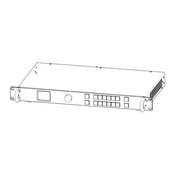
Page 14: Dimension
1.2.3 Dimension Following is the dimension of GX4 for your reference:: Dimension:480mm×303mm×45mm User Manual... -
Page 15: Chapter 2 Install Your Product
Chapter 2 Install Your Product 2.1 Plug in Signals Connect signals to the product (ensure all devices are powered off first). Tighten connector screws/locks where provided. 2.2 Plug in Main Power Connect IEC cable to device and plug into wall socket. Turn on power at wall socket. -
Page 16: Chapter 3 Use Your Product
Chapter 3 Use Your Product 3.1 Use the MENU Button Push【MENU】button to enter main menu. Turn the knob to select corresponding menu item. The symbol >indicate that the item is selected. Push the knob or【OK】button to confirm the operation. The symbol* means the selected item is under editing state, ready to be set or checked The operation diagram is as follows:... -
Page 17: Menu Structure
3.2 MENU Structure The MENU structure is shown in the figure below: User Manual... -
Page 18: Use The Menu
【MENU】 button and rotary knob in the front panel, the TST display will show the corresponding menus according to user selections. 3.3.1 LED Configuration GX4 is built in with Subito Sender which can control LED screen with RBGLink receivers. Here is the led configuration sub-menu. - Page 19 1. QUICK CONNECT >SEND CARD SET >> RECEIVE CARD SET >> RESET ALL CARD 1.1 SEND CARD SET >X SAVE SENDER CARD RESET SENDCARD X,Y : the horizontal and vertical position of the display that the Sender card control the on LED scressn One port of Subito Sender can control 650K pixels.
- Page 20 CHOOSE CABLE:choose the output LAN port on the Sender. There are 4 ports available. HORIZONTAL CARD: how many receive cards needed to receive the data that the chosen sender port offer WIDTH: width of each led cabinet HEIGHT:height of each led cabinet >HOR OFFSET VER OFFSET CONNECT TYPE...
- Page 21 2. ADVANCED >COLOR TEMP >> SYSTEM INFO >> OSD CONTROL >> TESTMODE NORMAL CLS SWITCH >LOCK SWITCH 2.1 COLOR TEMP SAVE TO SEND CARD >COLOR DEPTH 8 BIT >RED GREEN BLUE SENDCARD GAMMA 2.8 color temperature adjustment for led screen Color Depth: 8 bit, 10 bit, 12 bit RED,GREEN,BLUE: value range from 0 to 255 SENDER CARD GAMMA:value from range 0.0 to 9.9...
- Page 22 PREINSTALL FILE >> Users can load LED configuration files from LED manufacturers to the GX4 devices by XTOOL. There are 15 manufacturers items in the sub-menu and each manufacture can store 16 files. 270 files in total allow to be loaded.
-
Page 23: Output
4. OUT BRIGHT Output brightness to adjust the brightness of LED screen, value ranging from 0-255 3.3.2 Output TEXT OVERLAY >> OUTPUT INFO >> DISPLAY MODE >> OUTPUT FORMAT >> GAMMA LINEAR OUTPUT ADJUST >> SENDCARDTYPE OTHER SCREEN >> RATIO NORMAL OUTPUT INFO : show current input information... - Page 24 2. OUTPUT FORMAT >STANDARD >> CUSTOMIZE >> 2.1 STANDARD: standard output resolution, 26 types available to choose from 720x480i@60 to 2560x816@60 2.2 CUSTOMIZE: custom resolution CUSTOMIZE: >1920x1080@60 Turn the knob to resolution line and press the knob “>” (arrow )change to “*”...
- Page 25 Customize: Customize: *1450x900@00 *1450x900@60 Note: The number buttons lighting up indicate that users can use button to key in numbers. 3. OUTPUT ADJUST DVI MODE BITS 8 BIT COLOR SPACE IMAGE DE ADJUST >> RESET DVI MODE: DIV or HDMI BITS: DVI 8bit ,HDMI 8/10/12 bit COLOR SPACE: IMAGE or VIDEO DE ADJUST...
- Page 26 H POLARITY:horizontal polarity, POS (positive) or NEG (negative) V POLARITY:vertical polarity, POS (positive) or NEG (negative) RESET: reset above setting if not proper 4. SCREEN H POS RESET V POS H SIZE 1920 V SIZE 1080 MODE FULL SIZE The setting of <SCREEN> is based on the resolution of the LED screen,applicable under single picture mode.
- Page 27 by reset. Note:Users can also set <SCREEN> by 【FS】 . Push FSbutton light on, Led display image in screen size, Push 【FS】again, button light off, Led display image in full size. RATIO : NORMAL, 16:9, 4:3 6. TEXT OVERLAY Text overlay function is to add subtitle on output image, more often used on such fields as live broadcasting, live concert, live commentary, and...
- Page 28 LAYOUT PIP L+B >SWAP PICTURE ALPHA SELECT IMAGE A Select <SELECT> in 【PIP】menu, push【OK】 turn Knob to select”IMAGE B”, Push <SCALE> to set the size and position of ”IMAGE B” which the is case. VGA picture in th LAYOUT PIP L+B SWAP PICTURE ALPHA >SELECT...
- Page 29 Select <PRESET>Push 【OK】and turn the knob to “WhOnBk1”or “WhOnBk2” and Push 【OK】again Note:TEXT OVERLAY only support monochrome subtitles. TEXT OVERLAY >PRESET WhOnBk1 BLEND MODE MODE1 BLEND LEVEL STAND ABOVE PRESET:User, WhONBk1 (white on black ) WhONBk2 (white on black ),BkOnWh1(black on white),BkOnWh2(black on white), GrnOnBk1 (green on black),GrnOnBk2 (green on black), GrnOnWh1 (green on white)1...
- Page 30 7. DISPLAY MODE >MODE LIVE IMAGE TEST PATTERN 》 SOLID COLOR 》 MODE : BLACK OUT, LIVE IMAGE, FREEZE IMAGE,SOLID COLOR, TEST PATTERN TEST PATTERN AUTO SWITCH HOR STEP VER STEP COLOR WHITE TEST PATTERN:Value 0-66 AUTO SWITCH: ON or OFF HOR STEP:horizontal color graduation value 0-64 VER STEP:vertical color graduation value 0-64 COLOR:WHITE, BLUE, GREEN, RED.
- Page 31 8.GAMMA :LINEAR,sRGB, -1.2, 1.2, -1.4, 1.4, -1.6, 1.6 User Manual...
-
Page 32: Input
3.3.3 Input INPUT INFO >> SDI ADJUST >> SIZING ADJUST >> EDID MANAGE >> USB CONTROL >> VGA TYPE VGA ADJUST >> DVI4In1 NO EXT ADC AJUST >> 1. INPUT INFO Show the current input format and resolution 2. SIZE ADJUST MASK TOP >>... - Page 33 RESET SIZE:if the size is not proper, turn knob to RESET SIZE and press 【OK】 MASK TOP:crop the top of image MASK BOTTOM:crop the bottom of image MASK LEFT:crop the left part of image MASK RIGHT:crop the right part of image RESET MASK:If the crop not proper, turn knob to RESET MASK and press 【OK】.
- Page 34 >> AUTO ADUST RESET >> YES <OK>,NO <MENU> RESET YES <OK>,NO <MENU> 5. SDI ADJUT GX4 with SDI optional module come with SDI ADJUST in the menu. H POS V POS ANTI ALIAS STEP_0 RESET 6. EDID MANAGE DESTINATION HDMI...
- Page 35 Choose signal type for VGA button. VGA or YPbPr. 8.DVI4In1 DVI 4 In 1) GX4 with optional DVI module installed comes with such signal types as VGA, DVI, CVBS, YPbPr. It is offered to users to choose the signal type through the DVI connector which is compatible with VGA, DVI, CVBS, YPbPr via adapter.
-
Page 36: Transition
3.3.4 Transition Transition is used to set the switching mode between different input sources. >TAKE >MODE FADE DURATION 0.5S ALPHA DEINTERLACE IMAGE EHANCE MODE : Special effects switching modes, including FADE, CUT, WIPE SOUARE IN, WIPE SOUARE OUT, WIPE TOP LIEFT IN, WIPE TOP LIEFT OUT, WIPE TOP RIGHT IN, WIPE TOP RIGHT OUT, WIPE BOTTOM LEFT IN, WIPE BOTTOM LEFT OUT, WIPE BOTTOM RIGHT IN, WIPE BOTTOM LEFT OUT, WIPE LEFT IN, WIPE LEFT OUT, WIPE RIGHT IN, WIPE RIGHT OUT, WIPE... -
Page 37: Audio
3.3.5 Audio >MUTE VOLUME AUDIO IN IMAGE A HDMI INTERNAL MUTE:select ON or OFF Volume:adjustment range from 0 to 100 Users can also adjust volume without entering AUDIO menu. Rotate the knob anytime the LCD screen shows the main interface. AUDIO IN:select the source of the input audio from IMAGE A or IMAGE B HDMI:select internal or external audio for HMDI input User Manual... -
Page 38: Split
3.3.6 Split GX4 can be used in multiple cascade mode to finish split. When do cascade, connect the signals to the signal distributor first, and then connect from the outputs of the signal distributor to each input of GX4. User can also do cascade via HDMI LOOP port. - Page 39 When doing equal splitting, set H SIZE and V SIZE of each device with same resolution, and then set H POS and V POS of each device correspondingly. When doing unequal splitting, set and save H SIZE and V SIZE of each device according to actual needs. User Manual...
-
Page 40: System
LOCK FRONT PANEL >> LICENSE SET UP 1. SYSTEM INFO Show flowing information MCU VERSION, VIDEO VERSION, EXT VERSION, 2. TECH SUPPORT After-Sale Service: 4008-592-315 support@rgblink.com www.rgblink.com 3. WORK TIME WORK TIME >> TOTAL TIME >> BOOT TIMES WORK TIME: the consistent working time since Latest boot up. - Page 41 TOTLAL TIME: the accumulative working time since the first boot up. BOOT TIMES: the total boot up times up to now. 4. LOCK FRONT PANEL YES <OK>, NO <MENU> After the panel is locked, keep pressing MENU for 3 S to release the panel.
-
Page 42: Language
7. DELAY RECALL Value range from 0 to 255S 3.3.8 Language To swithc langue here. English or Chinese available. Or Keep pressing MENU and SCALE button for 3 S to switch language. 3.3.9 Factory Reset FACTORY RESET YES <OK>, NO <MENU> User Manual... -
Page 43: Shortcut Buttons
3.4 Shortcut Buttons GX4 comes with shortcut buttons to enter the sub-menu of certain features. Here are details of some quick buttons. 3.4.1【TAKE】Button When GX4 power on, system default HDMI input signal. To switch signal, press CVBS,VGA,DVI or SDI. For example, to switch to CVBS, push【CVBS】... - Page 44 To EnableTAKE mode , Keep pressing button for 3s and the TAKE MODE is ON The LCD sreen shows the info below for 2S TAKE MODE ON AUDIO INVALID And then go back to the main interface If user want to switch to VGA signal, push VGA button Then push TAKE button again.
- Page 45 with set transition effect. User Manual...
-
Page 46: Pip】Button
3.4.2【PIP】Button PIP mode cann’t be enabled unless TAKE MODE is OFF. Push button and button light is on. LCD shows the <PIP> menu. LAYOUT PIP L+B SWAP PICTURE ALPHA >SELECT IMAGE LAYOUT: There are 7 layouts available in the menu. PIP L+T, PIP R+T, PIP L+B, PIP R+B, PIP CENTER, PBP L+R and PBP T+B. - Page 47 ALPHA: Image transparency setting, the adjustment range is 0 to 16. SECLECT: Select IMAGE A or IMAGE B. User Manual...
-
Page 48: Scale】Button
3.4.3【SCALE】Button To scale the output image, users can press 【SCALE】 button and set the parameters by turning knob or pressing numeral buttons. After user press 【SCALE】, LCD shows the menu items as follows: H SIZE: set the horizontal pixels of output image V SIZE: set the vertical pixels of output image H POS: set the horizontal position of image V POS: set the horizontal position of image... -
Page 49: Freeze】Button
3.4.4【FREEZE】Button To freeze current output image, users can press 【FREEZE】on the front panel. LCD shows “FROZEN” in the state bar and the【FREEZE】 button light is on. To exit FREEZE mode, press【FREEZE】 again and the button light goes out. User Manual... -
Page 50: Bri】Button
3.4.5【BRI】Button Push【BRI】button and enter the image adjustment menu where users can adjust brightness, constrast, saturation,sharpness, color temperature of red, green and blue. *BRIGHTNESS GREEN CONTRAST BLUE SATRUATION RESET SHARPNESS BRIGHTNESS:range from 0 to 100. CONTRAST:range from 0 to 100. SATURATION:range from 0 to 100 SHAPRNESS:range from 38 to 62 RED:range from 0 to 100 GREEN:range from 0 to 100... -
Page 51: Save】Button
3.4.6【SAVE】Button Push the [SAVE] button, the button light is on, and enable the SAVE function. LCD shows [SAVE] instruction info to assist users complete operation. Meanwhile, part of numeral buttons 0~9 lights are on and parts flash.. Buttons with lights on are empty, flashing buttons are used. LCD shows as below SAVE TO >SAVE1... -
Page 52: Load】Button
3.4.7【LOAD】Button Push 【 LOAD 】 LCD shows the instruction information to assist users complete LOAD operation. Meanwhile, among numeral buttons 0-9, some buttons lights are on, some flash and perhaps some lights go off. Buttons with light on indicate the <SAVE> ready to load, flash indicate the <SAVE>... -
Page 53: Chapter 4 Ordering Codes
CHAPTER 4 ORDERING CODES 4.1 PRODUCT 820-1004-01-0 4.2 OPTIONS 4.2.1 Input Options 190-0001-04-2 Single DVI Input Module 190-0001-07-2 Single 3G SDI Input/Loop Module 190-0001-10-1 Single USB Input/Backup Module 190-0001-13-2 Single HDMI Input Module 190-0001-15-2 Single HDBaseT Input Module User Manual... -
Page 54: Chapter 5 Support
CHAPTER 5 Support 5.1 Contact Us User Manual... -
Page 55: Chapter 6 Appendix
CHAPTER 6 APPENDIX 6.1 Specification CVBS Input (Standard) Number of Inputs Connector Interface Appearance Supported PAL/NTSC Standard Signal Level 1Vpp±3db (0.7V Video+0.3v Sync ) 75 ohm Supported 480i | 576i Resolution User Manual... - Page 56 VGA Input (Standard) Number of Inputs Connector DB15 Supported VGA-UXGA Standard Interface Appearance Supported VESA 800×600@60 | 1024×768@60 Resolution 1280×1024@60 | 1440×900@60 | 1600×1200@60 User Manual...
- Page 57 HDMI Input (Standard) Number of 2 (1 IN|1 LOOP) Connectors Connector HDMI-A Interface Appearance Supported SMPTE 625/25/50 PAL, 525/29.97/59.94 Resolution NTSC, 720p50/59.94/60 | 1080i50/59.94/60 | 1080P50/59.94/60 VESA 800×600@60 | 1024×768@60 | 1280×768@60 | 1280×1024@60 | 1600×1200@60 | 1920×1080@60 Signal Level TMDS pwl, single pixel input,165MHz bandpixels Supported HDMI 1.3...
- Page 58 DVI Input (Standard) Number of Inputs Connector DVI-I Interface Appearance Supported SMPTE 480i NTSC,576i PAL, Resolution 720p50/59.94/60 | 1080i50/59.94/60 | 1080p50/59.94/60 VESA 800×600@60 | 1024×768@60 | 1280×768@60 |1280×1024@60 | 1600×1200@60 | 1920×1080@60 Supported Single Link DVI Standard User Manual...
- Page 59 3G-SDI Input (Optional) Number of 2 (1 IN|1 LOOP) Connectors Connector Interface Appearance Data Rate 2.97Gb/s | 2.97/1.001Gb/s | 1.485Gb/s | 1.485/1.001Gb/s | 270Mb/s Supported SMPTE 480i NTSC,576i PAL, Resolution 720p50/59.94/60 | 1080i50/59.94/60| 1080p50/59.94/60 SMPTE 425M (Level A & B) | SMPTE 424M | Supported SMPTE 292M | SMPTE 259M-C | DVB-ASI Standard...
- Page 60 HDBaseT Input (Optional) Number of Connectors Connector RJ45 Supported SMPTE 480i NTSC,576i PAL, Resolution 720p50/59.94/60 | 1080i50/59.94/60 | 1080p50/59.94/60 VESA 800×600@60 | 1024×768@60 | 1280×768@60 |1280×1024@60 | 1600×1200@60 | 1920×1080@60 User Manual...
- Page 61 DVI Output (Standard) Number of Outputs Connector DVI-I Interface Appearance Supported SMPTE 625/25/50 PAL, 525/29.97/59.94 Resolution NTSC, 720p50/59.94/60|1080i50/59.94/60| 1080P50/59.94/60 1280×720@23.98 | 1280×720@24 | 1280×720@25 | 1280×720@29.97 | 1280×720@30 | 1920×1080@23.98 | 1920×1080@24 | 1920×1080@25 | 1920×1080@29.97 | 1920×1080@30 VESA 800×600@60 | 1024×768@60 | 1024×768@75 | 1280×720@60 | 1280×720@50 | 1280×768@60 | 1280×800@60 | 1280×1024@60 |...
- Page 62 Subito Quatro Sender Number of Outputs Connector RJ45 Interface Appearance Performance Each Port Capacity 655,360 pixels Horizontal Range 3840 pixels Vertical Range 2048 pixels Features Grey 10 bit Processing Frame Rate Delay EDID Management User Manual...
- Page 63 Accessories and Operating Condition Communication RJ11/RS232 USB 2.0 Input Voltage AC100-240V/50-60HZ Max Power Working 0°C~45°C Temperature Working 10%~85% Humidity Warranty 3 Years User Manual...
-
Page 64: Load Led Configuration File
USB disk. 2.Download and install XTOOL V1.0.1.3. Download XTOOL from RGBLink www.rgblink.com/support#downloads 3.Connect GX4 and computer with the USB cable (USB A-B cable) from In The Box. 4.Open up XTOOL If you find it in Chinese, switch the language by clicking this 5.Set Connection... - Page 65 When it is done, a window will pop up showing “Serial port set” and the Device Type and SN (serial number) can be identified. 6.Click Screen File to load the LED configuration file saved previously. Select Manufacturer from 1 to 15 and File Index from 1 to 16. Type in the File Name according to real manufacturer and the LED screen specification.
- Page 66 7.When it is done, a window showing Set Success will pop up. The file has been loaded to the device and users can find and use the file in Menu Configuration - Config File - Preinstall File. Under the Manufacturer index set on XTOOL, there is the file name. Select the file, and press OK, the Led screen will be set as the configuration file.
-
Page 67: Terms & Definitions
6.3 Terms & Definitions The following terms and definitions are used throughout this guide. “ASCII”: American Standard for Information Interchange. The standard code consisting of 7-bit coded characters (8 bits including parity check) used to exchange information between data processing systems, data communication systems, and associated equipment. - Page 68 “BNC”: Bayonet Neill-Concelman. A cable connector used extensively in television and named for its inventors. A cylindrical bayonet connector that operates with a twist-locking motion. To make the connection, align the two curved grooves in the collar of the male connector with the two projections on the outside of the female collar, push, and twist.
- Page 69 Kelvin(K), of a light source. The higher the color temperature, the bluer the light. The lower the temperature, the redder the light. Benchmark color temperature for the A/V industry include 5000°K, 6500°K, and 9000°K. “Contrast ratio”: The radio of the high light output level divided by the low light output level.
- Page 70 operates over twisted pair and over coaxial cable at speeds starting at 10Mbps. For LAN interconnectivity, Ethernet is physical link and data link protocol reflecting the two lowest layers of the OSI Reference Model. “Frame”: In interlaced video, a frame is one complete picture. A video frame is made up of two fields, or two sets of interlaced lines.
- Page 71 be adjusted, allowing a selectable tradeoff between storage size and image quality. JPEG typically achieves 10:1 comPushion with little perceptible loss in image quality. Produces blocking artifacts. “MPEG”: Motion Picture Expect Group. A standard committee under the auspices of the International Standards Organization working on algorithm standards that allow digital comPushion, storage and transmission of moving image information such as motion video, CD-quality audio, and control data at CD-ROM...
- Page 72 color transmission system. “PIP”: Picture-in-Picture. A small picture within a larger picture created by scaling down one of the images to make it smaller. Each picture requires a separate video source such as a camera, VCR, or computer. Other forms of PIP displays include Picture-by-Picture (PBP) and Picture-with-Picture (PWP), which are commonly used with 16:9 aspect display devices.
- Page 73 the extent to which a given color in any image is free from white. The less white in a color, the truer the color or the greater its saturation. On a display device, the color control adjusts the saturation. Not to be confused with the brightness, saturation is the amount of pigment in a color, and not the intensity.
- Page 74 “Sync”: Synchronization. In video, sync is a means of controlling the timing of an event with respect to other events. This is accomplished with timing pulses to insure that each step in a process occurs at the correct time. For example, horizontal sync determines exactly when to begin each horizontal scan line.
- Page 75 analog signal with TTL level separate horizontal and vertical sync. The video outputs to a 15-pin HD connector and has a horizontal scan frequency of 31.5 kHz and vertical frequency of 70 Hz (Mode 1, 2) and 60 Hz (Mode 3). The signal is non-interlaced in modes 1, 2, and 3 and interlaced when using the 8514/A card (35.5 kHz, 86 Hz) in mode 4.
-
Page 76: Revison History
6.4 Revison History The table below lists the changes to the Video Processor User Manual. Version Time ECO# Description Editor V1.0 20190614 0000 Release Fanny V1.1 20190813 0001 Add “ Load Led Fanny configuration File User Manual...
Need help?
Do you have a question about the GX4 and is the answer not in the manual?
Questions and answers