Table of Contents
Advertisement
Advertisement
Chapters
Table of Contents

Related Manuals for Bosch Rexroth IndraControl VCP 05


Summary of Contents for Bosch Rexroth IndraControl VCP 05
- Page 1 Artisan Technology Group is your source for quality new and certified-used/pre-owned equipment SERVICE CENTER REPAIRS WE BUY USED EQUIPMENT • FAST SHIPPING AND DELIVERY Experienced engineers and technicians on staff Sell your excess, underutilized, and idle used equipment at our full-service, in-house repair center We also offer credit for buy-backs and trade-ins •...
- Page 2 Industrial Electric Drives Linear Motion and Service Mobile Hydraulics and Controls Assembly Technologies Pneumatics Automation Hydraulics Rexroth IndraControl VCP 05 R911299726 Edition 02 Project Planning Manual Artisan Technology Group - Quality Instrumentation ... Guaranteed | (888) 88-SOURCE | www.artisantg.com...
- Page 3 Bosch Rexroth AG | Electric Drives and Controls Rexroth IndraControl VCP 05 | R911299726 / 02 Rexroth IndraControl VCP 05 Title Project Planning Manual Type of Documentation DOK-SUPPL*-VCP05******-PR02-EN-P Document Typecode Document Number, 120-2100-B353-02/EN Internal File Reference This document serves to describe the different variants of the Pupose of Documentation VCP 05.
-
Page 4: Table Of Contents
R911299726 / 02 | Rexroth IndraControl VCP 05 Electric Drives and Controls | Bosch Rexroth AG Contents Contents System Presentation........1–1 Brief Description of the VCP 05 ........1–1 Operating System ............1–2 Commissioning ..............1–2 Important Directions for Use...... 2–1 Appropriate Use............... - Page 5 Bosch Rexroth AG | Electric Drives and Controls Rexroth IndraControl VCP 05 | R911299726 / 02 Contents 5.1.2 Mounting Cutout ............5–3 5.1.3 Side View, Mounting Depth .......... 5–4 5.1.3.1 Standard Device ............5–4 5.1.3.2 Field Bus Device............5–5 Display and Operating Components..6–1 Display................
- Page 6 R911299726 / 02 | Rexroth IndraControl VCP 05 Electric Drives and Controls | Bosch Rexroth AG Contents Maintenance and Installation ..... 8–1 General Information............8–1 Exchange of Hardware Components....... 8–1 Data Backup ..............8–1 Unpacking the Device............8–1 Identification ..............8–2 Connecting ..............
- Page 7 Bosch Rexroth AG | Electric Drives and Controls Rexroth IndraControl VCP 05 | R911299726 / 02 Contents Artisan Technology Group - Quality Instrumentation ... Guaranteed | (888) 88-SOURCE | www.artisantg.com...
-
Page 8: System Presentation
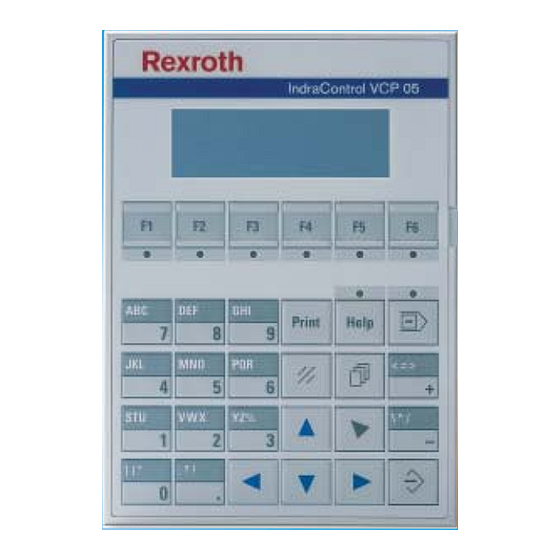
R911299726 / 02 | Rexroth IndraControl VCP 05 Electric Drives and Controls | Bosch Rexroth AG System Presentation System Presentation Brief Description of the VCP 05 The small operator terminal VCP 05 is a machine operator terminal which can initiate functions in the machine as defined in the applica- tion. -
Page 9: Operating System
Bosch Rexroth AG | Electric Drives and Controls Rexroth IndraControl VCP 05 | R911299726 / 02 System Presentation Operating System A special operating system is installed on the small operator terminal. If necessary, this operating system can be reloaded into the device (firm- ware download). -
Page 10: Important Directions For Use
If they are used in an inappropriate manner, then situations can develop that may lead to property damage or injury to personnel. Bosch Rexroth, as manufacturer, is not liable for any damages resulting from inappropriate use. In such cases, the guarantee and the right to payment of damages resulting from inappropriate use are forfeited. -
Page 11: Areas Of Use And Application
Important Directions for Use 2.1.2 Areas of Use and Application The small operator terminal VCP 05 made by Bosch Rexroth allows to operate and control machines and installations and serves to visualize the information on the machine/installation to be operated required by the user. -
Page 12: Safety Instructions For Electric Drives And Controls
If you do not have the user documentation for your equip- ment, contact your local Bosch Rexroth representative to send this documentation immediately to the person or persons responsible for the safe operation of this equipment. -
Page 13: Hazards By Improper Use
Risk of injury due to incorrect handling of batteries! General Information • Bosch Rexroth AG is not liable for damages resulting from failure to observe the warnings provided in this documentation. • Read the operating, maintenance and safety instructions in your lan- guage before starting up the machine. - Page 14 R911299726 / 02 | Rexroth IndraControl VCP 05 Electric Drives and Controls | Bosch Rexroth AG Safety Instructions for Electric Drives and Controls • Furthermore, they must be trained, instructed and qualified to switch electrical circuits and equipment on and off in accordance with tech- nical safety regulations, to ground them and to mark them according to the requirements of safe work practices.
-
Page 15: Protection Against Contact With Electrical Parts
Bosch Rexroth AG | Electric Drives and Controls Rexroth IndraControl VCP 05 | R911299726 / 02 Safety Instructions for Electric Drives and Controls Protection Against Contact with Electrical Parts This section refers to equipment and drive components with voltages above 50 Volts. -
Page 16: Protection Against Electric Shock By Protective Low Voltage (Pelv)
R911299726 / 02 | Rexroth IndraControl VCP 05 Electric Drives and Controls | Bosch Rexroth AG Safety Instructions for Electric Drives and Controls To be observed with electrical drive and filter components: DANGER High electrical voltage on the housing! High leakage current! Dan- ger to life, danger of injury by electric shock! •... -
Page 17: Protection Against Dangerous Movements
Bosch Rexroth AG | Electric Drives and Controls Rexroth IndraControl VCP 05 | R911299726 / 02 Safety Instructions for Electric Drives and Controls Protection Against Dangerous Movements Dangerous movements can be caused by faulty control of the con- nected motors. Some common examples are: •... - Page 18 R911299726 / 02 | Rexroth IndraControl VCP 05 Electric Drives and Controls | Bosch Rexroth AG Safety Instructions for Electric Drives and Controls • Fences and coverings must be strong enough to resist maximum possible momentum, especially if there is a possibility of loose parts flying off.
-
Page 19: Protection Against Magnetic And Electromagnetic Fields During Operation And Mounting
Bosch Rexroth AG | Electric Drives and Controls Rexroth IndraControl VCP 05 | R911299726 / 02 Safety Instructions for Electric Drives and Controls Protection Against Magnetic and Electromagnetic Fields During Operation and Mounting Magnetic and electromagnetic fields generated near current-carrying... -
Page 20: Protection During Handling And Mounting
R911299726 / 02 | Rexroth IndraControl VCP 05 Electric Drives and Controls | Bosch Rexroth AG Safety Instructions for Electric Drives and Controls 3.10 Protection During Handling and Mounting Under certain conditions, incorrect handling and mounting of parts and components may cause injuries. -
Page 21: Protection Against Pressurized Systems
3-10 Bosch Rexroth AG | Electric Drives and Controls Rexroth IndraControl VCP 05 | R911299726 / 02 Safety Instructions for Electric Drives and Controls 3.12 Protection Against Pressurized Systems Certain motors and drive controllers, corresponding to the information in the respective Project Planning Manual, must be provided with pres- surized media, such as compressed air, hydraulic oil, cooling fluid and cooling lubricant supplied by external systems. -
Page 22: Technical Data
R911299726 / 02 | Rexroth IndraControl VCP 05 Electric Drives and Controls | Bosch Rexroth AG Technical Data Technical Data Front Panel and Housing Front Panel and Housing Housing Steel Sheet, Galvanized Front Panel Aluminium, Varnished 168 mm x 120 mm x 4 mm (H x W x D) -
Page 23: Display
Bosch Rexroth AG | Electric Drives and Controls Rexroth IndraControl VCP 05 | R911299726 / 02 Technical Data Display Display Type LCD-Module with LED Backlight Resolution 4 x 20 Characters Reading Angle 90° Default Contrast Setting By User Mode Switch... -
Page 24: Interfaces
R911299726 / 02 | Rexroth IndraControl VCP 05 Electric Drives and Controls | Bosch Rexroth AG Technical Data Interfaces Standard Interfaces Variable Baud Rates and Data Formats X3 SER1 TTY / 20 mA According to CL 2 and DIN 66 348 T1 Transmission Length: 0 - 1000 m (3280.84 ft.), Twisted... -
Page 25: Connection System
Bosch Rexroth AG | Electric Drives and Controls Rexroth IndraControl VCP 05 | R911299726 / 02 Technical Data Connection System Connection System D-SUB Female and Male Connector Strips, 9-Pin and 25-Pin Female and Male Connector Strips Phoenix COMBICON, 3-Pin Ambient Conditions... -
Page 26: Compatibility Test
R911299726 / 02 | Rexroth IndraControl VCP 05 Electric Drives and Controls | Bosch Rexroth AG Technical Data 4.10 Compatibility Test All Rexroth controls and drives are developed and tested according to the technological state-of-the-art. As it is impossible to follow the continuing development of all materials (e.g. - Page 27 Bosch Rexroth AG | Electric Drives and Controls Rexroth IndraControl VCP 05 | R911299726 / 02 Technical Data Artisan Technology Group - Quality Instrumentation ... Guaranteed | (888) 88-SOURCE | www.artisantg.com...
-
Page 28: Dimensions
R911299726 / 02 | Rexroth IndraControl VCP 05 Electric Drives and Controls | Bosch Rexroth AG Dimensions Dimensions Installation When installing the operator terminal, keep a minimum clearance of 30 mm (1.181") around the operator terminal to ensure adequate air cir- culation. -
Page 29: Front Panel Dimensions
Bosch Rexroth AG | Electric Drives and Controls Rexroth IndraControl VCP 05 | R911299726 / 02 Dimensions 5.1.1 Front Panel Dimensions Fig. 5-1: Front panel dimensions Artisan Technology Group - Quality Instrumentation ... Guaranteed | (888) 88-SOURCE | www.artisantg.com... -
Page 30: Mounting Cutout
R911299726 / 02 | Rexroth IndraControl VCP 05 Electric Drives and Controls | Bosch Rexroth AG Dimensions 5.1.2 Mounting Cutout Fig. 5-2: Mounting cutout A Mounting Cutout B Front Panel Artisan Technology Group - Quality Instrumentation ... Guaranteed | (888) 88-SOURCE | www.artisantg.com... -
Page 31: Side View, Mounting Depth
Bosch Rexroth AG | Electric Drives and Controls Rexroth IndraControl VCP 05 | R911299726 / 02 Dimensions 5.1.3 Side View, Mounting Depth 5.1.3.1 Standard Device Fig. 5-3: Side view and mounting depth, standard device 1 Front Panel 2 Circumferential Seal 3 Mounting Surface Thickness 1 mm to 14 mm (0.039"... -
Page 32: Field Bus Device
R911299726 / 02 | Rexroth IndraControl VCP 05 Electric Drives and Controls | Bosch Rexroth AG Dimensions 5.1.3.2 Field Bus Device Fig. 5-4: Side view and mounting depth, field bus device 1 Front Panel 2 Circumferential Seal 3 Mounting Surface Thickness 1 mm to 14 mm (0.039" to 0.551") 4 Threaded Pin DIN 914 M4 x 35 mm (1.378") - Page 33 Bosch Rexroth AG | Electric Drives and Controls Rexroth IndraControl VCP 05 | R911299726 / 02 Dimensions Artisan Technology Group - Quality Instrumentation ... Guaranteed | (888) 88-SOURCE | www.artisantg.com...
-
Page 34: Display And Operating Components
R911299726 / 02 | Rexroth IndraControl VCP 05 Electric Drives and Controls | Bosch Rexroth AG Display and Operating Components Display and Operating Components Display Danger of intoxication! If the display is damaged, avoid touching, swallowing or breathing in the liquids or gases which may leak out. -
Page 35: Default Contrast Setting
Bosch Rexroth AG | Electric Drives and Controls Rexroth IndraControl VCP 05 | R911299726 / 02 Display and Operating Components 6.1.2 Default Contrast Setting If the contrast setting is such that it is no longer possible to read the masks, you can use the user mode switch to reset the contrast to the default value. -
Page 36: Character Set Katakana
R911299726 / 02 | Rexroth IndraControl VCP 05 Electric Drives and Controls | Bosch Rexroth AG Display and Operating Components 6.1.4.1 Character Set Katakana Fig. 6-2: Character set Katakana Artisan Technology Group - Quality Instrumentation ... Guaranteed | (888) 88-SOURCE | www.artisantg.com... -
Page 37: Keypad
Bosch Rexroth AG | Electric Drives and Controls Rexroth IndraControl VCP 05 | R911299726 / 02 Display and Operating Components Keypad The keys are positioned under an environmental-proof polyester foil. You project the operating principle of the keys in the programming soft- ware. -
Page 38: Navigation Keys
R911299726 / 02 | Rexroth IndraControl VCP 05 Electric Drives and Controls | Bosch Rexroth AG Display and Operating Components The key 8 and DEF is used for changing data in the editor. The charac- ters D, E and F can be entered when configuring the Shift or ShiftCase system variables. -
Page 39: Special Keys
Bosch Rexroth AG | Electric Drives and Controls Rexroth IndraControl VCP 05 | R911299726 / 02 Display and Operating Components The key Cursor home can be programmed to directly select higher- level nodes and I/O masks. In the editor it returns the cursor to the first input variable position. -
Page 40: Function Keys
R911299726 / 02 | Rexroth IndraControl VCP 05 Electric Drives and Controls | Bosch Rexroth AG Display and Operating Components 6.2.4 Function Keys The function of the function keys can be freely assigned (with soft key functions). The function keys can used either as direct keys for menu control of for triggering a function in the control system. -
Page 41: User Mode Switch
Bosch Rexroth AG | Electric Drives and Controls Rexroth IndraControl VCP 05 | R911299726 / 02 Display and Operating Components 6.2.5 User Mode Switch The user mode switch is located on the rear of the small operator termi- nal. The switch positions for ON or OFF are printed onto the user mode switch. -
Page 42: Interfaces
R911299726 / 02 | Rexroth IndraControl VCP 05 Electric Drives and Controls | Bosch Rexroth AG Interfaces Interfaces The device can either be supplied as a standard device or field bus device. The universal interface X3 combines several interface standards in one connector. -
Page 43: Standard Interfaces
Bosch Rexroth AG | Electric Drives and Controls Rexroth IndraControl VCP 05 | R911299726 / 02 Interfaces Standard Interfaces Fig. 7-2: Rear view of standard device Artisan Technology Group - Quality Instrumentation ... Guaranteed | (888) 88-SOURCE | www.artisantg.com... - Page 44 R911299726 / 02 | Rexroth IndraControl VCP 05 Electric Drives and Controls | Bosch Rexroth AG Interfaces 1. Fastening Screws 2. Female Connector X3 (TTY/RS485/RS232c) 3. Termination Switch (X3-SER1 RS485) 4. Connector X1 (Supply Voltage) 5. Threaded Bolt for Protective Grounding 6.
-
Page 45: Tty / 20 Ma Current Loop (X3-Ser1)
Bosch Rexroth AG | Electric Drives and Controls Rexroth IndraControl VCP 05 | R911299726 / 02 Interfaces 7.1.1 TTY / 20 mA Current Loop (X3-SER1) Depending on the wiring, it is possible to connect the interface either as an active or passive current loop. The transmit line and the receive line are each provided with a separate 20 mA power source. -
Page 46: Termination
R911299726 / 02 | Rexroth IndraControl VCP 05 Electric Drives and Controls | Bosch Rexroth AG Interfaces Pin Designation Function Transmitted Data, Positive Polarity Power Source 1, Positive Polarity Received Data, Positive Polarity Received Data, Negative Polarity Power Source 2, Positive Polarity... -
Page 47: Rs485 (X3-Ser1)
Bosch Rexroth AG | Electric Drives and Controls Rexroth IndraControl VCP 05 | R911299726 / 02 Interfaces 7.1.2 RS485 (X3-SER1) The interface is suitable for point-to-point and for multi-point connec- tions. The wires belonging together are marked with „A“ and „B“. Some descriptions refer to the pins with „+“... -
Page 48: Fig. 7-8: Block Diagram Termination Rs485
R911299726 / 02 | Rexroth IndraControl VCP 05 Electric Drives and Controls | Bosch Rexroth AG Interfaces Fig. 7-8: Block diagram termination RS485 Designation Value R1, R3 510 Ohm 150 Ohm 120 Ohm Fig. 7-9: Resistance values termination RS485 The switch positions for ON or OFF are printed onto the termination switch. -
Page 49: Rs232C (X3-Ser1)
Bosch Rexroth AG | Electric Drives and Controls Rexroth IndraControl VCP 05 | R911299726 / 02 Interfaces 7.1.3 RS232c (X3-SER1) The interface is suitable to establish a point-to-point connection. 7.1.3.1 Pin Assignment Fig. 7-11: 25 pin D-SUB female connector strip... -
Page 50: Rs232C (X3-Ser2)
R911299726 / 02 | Rexroth IndraControl VCP 05 Electric Drives and Controls | Bosch Rexroth AG Interfaces 7.1.4 RS232c (X3-SER2) The interface is only designed to be used for downloads, uploads, a scanner or a logging printer because the interface is not electrically iso- lated. -
Page 51: Field Bus Interfaces
7-10 Bosch Rexroth AG | Electric Drives and Controls Rexroth IndraControl VCP 05 | R911299726 / 02 Interfaces Field Bus Interfaces 7.2.1 DeviceNet (X2.1 / X2.2) The device can be integrated into the DeviceNet bus using the inter- faces available for DeviceNet connections. - Page 52 R911299726 / 02 | Rexroth IndraControl VCP 05 Electric Drives and Controls | Bosch Rexroth AG 7-11 Interfaces 1. Fastening Screws 2. Female Connector X2.2 (DeviceNet) 3. Female Connector X3 (SER2 RS232c) 4. Male Connector X2.1 (DeviceNet) 5. Connector X1 (Supply Voltage) 6.
-
Page 53: Pin Assignment
7-12 Bosch Rexroth AG | Electric Drives and Controls Rexroth IndraControl VCP 05 | R911299726 / 02 Interfaces 7.2.1.1 Pin Assignment Fig. 7-16: 9-pin D-SUB male and female connector strip Connector in the small operator terminal: 9-pin D-SUB male and female connector strip (assignment for male and female connector strip is the same). -
Page 54: Termination
R911299726 / 02 | Rexroth IndraControl VCP 05 Electric Drives and Controls | Bosch Rexroth AG 7-13 Interfaces The maximum length allowed for spur lines connected to the bus cable is 6 meters. The overall length of the bus cable including all spur lines is not to exceed the maximum length listed in the table below. -
Page 55: Interbus (X2.1 / X2.2)
7-14 Bosch Rexroth AG | Electric Drives and Controls Rexroth IndraControl VCP 05 | R911299726 / 02 Interfaces 7.2.2 INTERBUS (X2.1 / X2.2) The device can be integrated into the INTERBUS using the interfaces available for INTERBUS connections. Fig. 7-22: Rear view INTERBUS... - Page 56 R911299726 / 02 | Rexroth IndraControl VCP 05 Electric Drives and Controls | Bosch Rexroth AG 7-15 Interfaces 1. Fastening Screws 2. Female Connector X2.2 (Remotebus out) 3. Female Connector X3 (SER2 RS232c) 4. Male Connector X2.1 (Remotebus in) 5. Connector X1 (Supply Voltage) 6.
-
Page 57: Pin Assignment
7-16 Bosch Rexroth AG | Electric Drives and Controls Rexroth IndraControl VCP 05 | R911299726 / 02 Interfaces 7.2.2.1 Pin Assignment Fig. 7-23: 9-pin D-SUB male and female connector strip Connector in the small operator terminal: 9-pin D-SUB male connector strip for remote bus in. -
Page 58: Cable
R911299726 / 02 | Rexroth IndraControl VCP 05 Electric Drives and Controls | Bosch Rexroth AG 7-17 Interfaces 7.2.2.2 Cable A shielded twisted-pair cable (cable type LiYCY-TP) must be used. The maximum cable length depends on its use within the INTERBUS topol- ogy. -
Page 59: Profibus Dp (X2)
7-18 Bosch Rexroth AG | Electric Drives and Controls Rexroth IndraControl VCP 05 | R911299726 / 02 Interfaces 7.2.3 PROFIBUS DP (X2) The interface for PROFIBUS DP connections is available to integrate the device into a PROFIBUS DP structure. Fig. 7-28: Rear view PROFIBUS DP... - Page 60 R911299726 / 02 | Rexroth IndraControl VCP 05 Electric Drives and Controls | Bosch Rexroth AG 7-19 Interfaces 1. Fastening Screws 2. Female Connector X2 (PROFIBUS DP) 3. Female Connector X3 (SER2 RS232c) 4. Connector X1 (Supply Voltage) 5. Threaded Bolt for Protective Grounding 6.
-
Page 61: Pin Assignment
7-20 Bosch Rexroth AG | Electric Drives and Controls Rexroth IndraControl VCP 05 | R911299726 / 02 Interfaces 7.2.4 Pin Assignment Fig. 7-29: 9-pin D-SUB female connector strip Connector in the small operator terminal: 9-pin D-SUB female connec- tor strip... -
Page 62: Termination
R911299726 / 02 | Rexroth IndraControl VCP 05 Electric Drives and Controls | Bosch Rexroth AG 7-21 Interfaces The maximum cable length depends on the baud rate (DIN EN 19245 Part 3). Baud Rate Cable Length 187.5 kbits/s 1000 m... -
Page 63: Shielding D-Sub Connectors
7-22 Bosch Rexroth AG | Electric Drives and Controls Rexroth IndraControl VCP 05 | R911299726 / 02 Interfaces Shielding D-SUB Connectors You must shield D-SUB connectors as follows: Fig. 7-34: Shielding D-SUB connectors 1 D-SUB connector 2 Shield 3 Cable clip... -
Page 64: Maintenance And Installation
Data Backup CAUTION The Bosch Rexroth AG is not liable for possible data loss and the damages resulting from this! The customer himself is responsible for the backup of customer-specific data and must provide this data in case of service. -
Page 65: Identification
Bosch Rexroth AG | Electric Drives and Controls Rexroth IndraControl VCP 05 | R911299726 / 02 Maintenance and Installation Identification You can identify the small operator terminal by the nameplate on the rear. Fig. 8-1: Nameplate (example) 1 Ordering name / Short type designation... -
Page 66: Connecting
R911299726 / 02 | Rexroth IndraControl VCP 05 Electric Drives and Controls | Bosch Rexroth AG Maintenance and Installation Connecting 8.6.1 Supply Voltage 24 V The supply voltage is supplied via connector X1. The device has reverse polarity protection. In case of wrong polarity, the device will not operate. -
Page 67: Fig. 8-3: Preparing The Cable
Bosch Rexroth AG | Electric Drives and Controls Rexroth IndraControl VCP 05 | R911299726 / 02 Maintenance and Installation Use the following procedure to connect the device to the supply volt- age: 1. Remove approx. 30 mm (1.181") off the outer cable sheath and ap- prox. -
Page 68: Front Panel
R911299726 / 02 | Rexroth IndraControl VCP 05 Electric Drives and Controls | Bosch Rexroth AG Maintenance and Installation 3. Plug the female connector strip onto connector X1.A. Fig. 8-5: Female connector strip is plugged on 4. Secure the female connector strip in place with a screw-type locking to prevent it from slipping out. -
Page 69: Battery
Bosch Rexroth AG | Electric Drives and Controls Rexroth IndraControl VCP 05 | R911299726 / 02 Maintenance and Installation Battery The built-in battery preserves the data in the CMOS-RAM and supplies the real-time clock. The minimum battery life is 5 years, even under unfavorable operating conditions. -
Page 70: Ordering Information
R911299726 / 02 | Rexroth IndraControl VCP 05 Electric Drives and Controls | Bosch Rexroth AG Ordering Information Ordering Information Type Code The small operator terminals VCP 05 are available in different variants. Type code: Abbrev. Column 1 2 3 4... -
Page 71: Accessories
Bosch Rexroth AG | Electric Drives and Controls Rexroth IndraControl VCP 05 | R911299726 / 02 Ordering Information Accessories Ordering Designation Material Number Description 1070917922 Battery IKB0053 R911305271 Download cable IKB0033 R911291808 PROFIBUS cable IKB0051 R911305089 Serial cable RS422 IKB0052... - Page 72 R911299726 / 02 | Rexroth IndraControl VCP 05 Electric Drives and Controls | Bosch Rexroth AG 10-1 List of Figures List of Figures Fig. 1-1: VCP 05 with keypad 1-1 Fig. 3-1: Hazard classification (according to ANSI Z535) 3-1 Fig. 5-1: Front panel dimensions 5-2 Fig.
- Page 73 10-2 Bosch Rexroth AG | Electric Drives and Controls Rexroth IndraControl VCP 05 | R911299726 / 02 List of Figures Fig. 9-2: Accessories 9-2 Artisan Technology Group - Quality Instrumentation ... Guaranteed | (888) 88-SOURCE | www.artisantg.com...
-
Page 74: Index
R911299726 / 02 | Rexroth IndraControl VCP 05 Electric Drives and Controls | Bosch Rexroth AG 11-1 Index Index Battery 8-6 Battery disposal 8-6 Cable DeviceNet 7-12 INTERBUS 7-17 PROFIBUS DP 7-20 Changing the battery 8-6 Character attributes 6-2 Character set... - Page 75 11-2 Bosch Rexroth AG | Electric Drives and Controls Rexroth IndraControl VCP 05 | R911299726 / 02 Index Keypad 6-4 LcdContrast 6-1 Nameplate 8-2 Pin assignment DeviceNet 7-12 INTERBUS 7-16 PROFIBUS DP 7-20 RS232c 7-8, RS485 7-6 TTY / 20 mA 7-4...
-
Page 76: Service & Support
R911299726 / 02 | Rexroth IndraControl VCP 05 Electric Drives and Controls | Bosch Rexroth AG 12-1 Service & Support Service & Support 12.1 Helpdesk Unser Kundendienst-Helpdesk im Hauptwerk Lohr Our service helpdesk at our headquarters in Lohr am am Main steht Ihnen mit Rat und Tat zur Seite. -
Page 77: Vor Der Kontaktaufnahme
12-2 Bosch Rexroth AG | Electric Drives and Controls Rexroth IndraControl VCP 05 | R911299726 / 02 Service & Support 12.4 Vor der Kontaktaufnahme... - Before contacting us... Wir können Ihnen schnell und effizient helfen wenn or quick and efficient help, please have the... -
Page 78: Europa (West) - Europe (West)
R911299726 / 02 | Rexroth IndraControl VCP 05 Electric Drives and Controls | Bosch Rexroth AG 12-3 Service & Support 12.5.2 Europa (West) - Europe (West) vom Ausland: (0) nach Landeskennziffer weglassen, Italien: 0 nach Landeskennziffer mitwählen from abroad: don’t dial (0) after country code,... -
Page 79: Europa (Ost) - Europe (East)
12-4 Bosch Rexroth AG | Electric Drives and Controls Rexroth IndraControl VCP 05 | R911299726 / 02 Service & Support 12.5.3 Europa (Ost) - Europe (East) vom Ausland: (0) nach Landeskennziffer weglassen from abroad: don’t dial (0) after country code... -
Page 80: Afrika, Asien, Australien (Inkl. Pazifischer Raum) - Africa, Asia, Australia (Incl. Pacific Rim)
R911299726 / 02 | Rexroth IndraControl VCP 05 Electric Drives and Controls | Bosch Rexroth AG 12-5 Service & Support 12.5.4 Afrika, Asien, Australien (inkl. Pazifischer Raum) - Africa, Asia, Australia (incl. Pacific Rim) Australia - Australien Australia - Australien... -
Page 81: Nordamerika - North America
12-6 Bosch Rexroth AG | Electric Drives and Controls Rexroth IndraControl VCP 05 | R911299726 / 02 Service & Support 12.5.5 Nordamerika - North America Central Region - Mitte Southeast Region - Südwest USA SERVICE-HOTLINE Headquarters - Hauptniederlassung Bosch Rexroth Corporation... - Page 82 Artisan Technology Group - Quality Instrumentation ... Guaranteed | (888) 88-SOURCE | www.artisantg.com...
- Page 83 Bosch Rexroth AG Electric Drives and Controls P.O. Box 13 57 97803 Lohr, Germany Bgm.-Dr.-Nebel-Str. 2 97816 Lohr, Germany Phone +49 93 52-40-50 60 +49 93 52-40-49 4 1 service.svc@boschrexroth.de www.boschrexroth.com Printed in Germany R911299726 DOK-SUPPL*-VCP05******-PR02-EN-P Artisan Technology Group - Quality Instrumentation ... Guaranteed | (888) 88-SOURCE | www.artisantg.com...
- Page 84 Artisan Technology Group is your source for quality new and certified-used/pre-owned equipment SERVICE CENTER REPAIRS WE BUY USED EQUIPMENT • FAST SHIPPING AND DELIVERY Experienced engineers and technicians on staff Sell your excess, underutilized, and idle used equipment at our full-service, in-house repair center We also offer credit for buy-backs and trade-ins •...
Need help?
Do you have a question about the Rexroth IndraControl VCP 05 and is the answer not in the manual?
Questions and answers