Table of Contents
Advertisement
Quick Links
Advertisement
Chapters
Table of Contents

Related Manuals for Bosch Rexroth VAM 10.1


Summary of Contents for Bosch Rexroth VAM 10.1
- Page 1 Industrial Electric Drives Linear Motion and Service Mobile Hydraulics and Controls Assembly Technologies Pneumatics Automation Hydraulics Rexroth IndraControl VCP 20 Rexroth VAM 10.1 R911306781 Edition 02 Rexroth VAM 40.1 Project Planning Manual...
- Page 2 About this Documentation VAM 10.1 / VAM 40.1 Rexroth VAM 10.1 Title Rexroth VAM 40.1 Project Planning Manual Type of Documentation DOK-SUPPL*-VAM*10/40**-PR02-EN-P Document Typecode Document Number, 120-2100-B365-02/EN Internal File Reference This documentation describes the machine operator panels VAM 10.1 Purpose of Documentation and VAM 40.1.
-
Page 3: Table Of Contents
VAM 10.1 / VAM 40.1 Contents Contents System Presentation Brief Description ........................... 1-1 Machine Operator Panel VAM 10.1....................1-1 Machine Operator Panel VAM 40.1....................1-2 Use of the Machine Operator Panels in Residential Areas ............1-2 Important Directions for Use Appropriate Use.......................... - Page 4 Contents VAM 10.1 / VAM 40.1 Dimensions Housing Dimensions........................5-1 Housing Dimensions VAM 10.1, Front, Side and Top View............ 5-1 Housing Dimensions VAM 10.1, Rear View ................5-1 Housing Dimensions VAM 40.1, Front, Side and Top View............ 5-2 Housing Dimensions VAM 40.1, Rear View ................5-2 Installation.............................
- Page 5 VAM 10.1 / VAM 40.1 Contents Address Assignment........................8-6 Keypads........................... 8-6 Override Rotary Switch......................8-7 Digital 24 V Inputs and Outputs....................8-8 External Hand-Held Terminal ....................8-8 Internal Handwheel........................8-8 Configuration Specification ......................8-9 VAM 10.1-PB-NA-TA-TA-VB-1608-NN ................... 8-9 VAM 40.1-PB-NA-TA-TA-VB-1608-NN ................... 8-9 Exemplary Configuration with IndraLogic ...................
- Page 6 Contents VAM 10.1 / VAM 40.1 DOK-SUPPL*-VAM*10/40**-PR02-EN-P...
-
Page 7: System Presentation
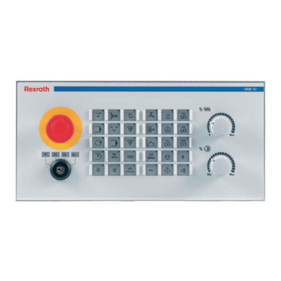
VAM 10.1 / VAM 40.1 System Presentation System Presentation Brief Description Machine operator panels complete machine operator terminals and are used to select the operating modes as well as to operate the machine manually. Thus, they contain the necessary operating elements, e. g., keys with LED displays, rotary switches for feed and spindle override, E- STOP pushbuttons, key switches and machine pushbuttons. -
Page 8: Machine Operator Panel Vam 10.1
System Presentation VAM 10.1 / VAM 40.1 Machine Operator Panel VAM 40.1 In addition to the components of the VAM 10.1 the VAM 40.1 provides as partly modular variant a flexible fifth module slot. Initially, as default variant for the fifth module slot a preconfigured module with two machine pushbuttons (white lit and red unlit) is provided. -
Page 9: Important Directions For Use
The user alone carries all responsibility of the risks. Before using Bosch Rexroth products, make sure that all the pre- requisites for appropriate use of the products are satisfied: •... -
Page 10: Areas Of Use And Application
This includes, for example, operation under water, in the case of extreme temperature fluctuations or extremely high maximum temperatures or if • Bosch Rexroth has not specifically released them for that intended purpose. Please note the specifications outlined in the general Safety Guidelines! DOK-SUPPL*-VAM*10/40**-PR02-EN-P... -
Page 11: Safety Instructions For Electric Drives And Controls
If you do not have the user documentation for your equipment, contact your local Bosch Rexroth representative to send this documentation immediately to the person or persons responsible for the safe operation of this equipment. -
Page 12: Hazards By Improper Use
Safety Instructions for Electric Drives and Controls VAM 10.1 / VAM 40.1 Hazards by Improper Use High voltage and high discharge current! Danger to life or severe bodily harm by electric shock! DANGER Dangerous movements! Danger to life, severe bodily harm or material damage by unintentional motor movements! DANGER High electrical voltage due to wrong... -
Page 13: General Information
VAM 10.1 / VAM 40.1 Safety Instructions for Electric Drives and Controls General Information • Bosch Rexroth AG is not liable for damages resulting from failure to observe the warnings provided in this documentation. • Read the operating, maintenance and safety instructions in your language before starting up the machine. -
Page 14: Protection Against Contact With Electrical Parts
Safety Instructions for Electric Drives and Controls VAM 10.1 / VAM 40.1 • Operation is only permitted if the national EMC regulations for the application are met. The instructions for installation in accordance with EMC requirements can be found in the documentation "EMC in Drive and Control Systems". -
Page 15: Protection Against Electric Shock By Protective Low Voltage (Pelv)
VAM 10.1 / VAM 40.1 Safety Instructions for Electric Drives and Controls To be observed with electrical drive and filter components: High electrical voltage on the housing! High leakage current! Danger to life, danger of injury by electric shock! ⇒ Connect the electrical equipment, the housings of all DANGER electrical units and motors permanently with the safety... -
Page 16: Protection Against Dangerous Movements
Safety Instructions for Electric Drives and Controls VAM 10.1 / VAM 40.1 Protection Against Dangerous Movements Dangerous movements can be caused by faulty control of the connected motors. Some common examples are: • improper or wrong wiring of cable connections •... -
Page 17: Protection Against Magnetic And Electromagnetic Fields During Operation And Mounting
VAM 10.1 / VAM 40.1 Safety Instructions for Electric Drives and Controls ⇒ Secure vertical axes against falling or dropping after switching off the motor power by, for example: - mechanically securing the vertical axes - adding an external braking/ arrester/ clamping mechanism - ensuring sufficient equilibration of the vertical axes The standard equipment motor brake or an external... -
Page 18: Protection Against Contact With Hot Parts
Safety Instructions for Electric Drives and Controls VAM 10.1 / VAM 40.1 Protection Against Contact with Hot Parts Housing surfaces could be extremely hot! Danger of injury! Danger of burns! ⇒ Do not touch housing surfaces near sources of heat! Danger of burns! CAUTION After switching the equipment off, wait at least ten (10) -
Page 19: 3.11 Battery Safety
VAM 10.1 / VAM 40.1 Safety Instructions for Electric Drives and Controls 3.11 Battery Safety Batteries contain reactive chemicals in a solid housing. Inappropriate handling may result in injuries or material damage. Risk of injury by incorrect handling! ⇒ Do not attempt to reactivate discharged batteries by heating or other methods (danger of explosion and cauterization). - Page 20 3-10 Safety Instructions for Electric Drives and Controls VAM 10.1 / VAM 40.1 Notes DOK-SUPPL*-VAM*10/40**-PR02-EN-P...
-
Page 21: Technical Data
VAM 10.1 / VAM 40.1 Technical Data Technical Data Basic Device VAM 10.1 VAM 40.1 IP 54 (front) Degree of protection Type 1 according to NEMA (UL) 1 according to DIN EN 50178 Protection class RAL 7035 light gray Color of the front foil Dimensions (W x H x D) 350 mm x 169 mm x 102 mm 407 mm x 169 mm x 102 mm... -
Page 22: Key Switch
Technical Data VAM 10.1 / VAM 40.1 Key Switch • 1-pin General Specifications: • 4-stage • Removal only in left position (position 1) • Contacts electrically isolated • Forced opening contact Contact Assignment of the Key Switch Position Contacts closed Fig. -
Page 23: Machine Pushbutton And E-Stop
VAM 10.1 / VAM 40.1 Technical Data Machine Pushbutton and E-STOP Vendor Télémecanique (Schneider Electric) Vendor's designation Standard auxilary switch, NO contact ZBE-101 Standard auxilary switch, NC contact ZBE-102 (with forced opening) LED module 24 V ZBV-B1 Connection cross-section Min. without connector sleeve 1 x 0.22 mm²... -
Page 24: Used Standards
(e.g. lubricants in machine tools) which may interact with our controls and drives, it cannot be completely ruled out that any reactions with the materials used by Bosch Rexroth might occur. For this reason, before using the respective material a compatibility test has to be carried out for new lubricants, cleaning agents etc. -
Page 25: Dimensions
VAM 10.1 / VAM 40.1 Dimensions Dimensions Housing Dimensions Housing Dimensions VAM 10.1, Front, Side and Top View 42.7 167.5 167.5 VAM_10_Bemaßung_01.FH9 Fig. 5-1: Housing dimensions VAM 10.1, front, side and top view Housing Dimensions VAM 10.1, Rear View VAM_10_Bemaßung_02.FH9 Fig. -
Page 26: Housing Dimensions Vam 40.1, Front, Side And Top View
Dimensions VAM 10.1 / VAM 40.1 Housing Dimensions VAM 40.1, Front, Side and Top View 41.7 VAM_40_Bemaßung_01.FH9 Fig. 5-3: Housing dimensions VAM 40.1, front, side and top view Housing Dimensions VAM 40.1, Rear View VAM_40_Bemaßung_02.FH9 Fig. 5-4: Housing dimensions VAM 40.1, rear view DOK-SUPPL*-VAM*10/40**-PR02-EN-P... -
Page 27: Installation
VAM 10.1 / VAM 40.1 Dimensions Installation Installation Notes • When installing the operator panel , observe to ensure an ergonomic operation. Additionally, ensure that all moving machine components are in sight of the operator. • Avoid installation locations exposed to direct sunlight, as additional heat development can occur. -
Page 28: Mounting Dimensions Vam 10.1
Dimensions VAM 10.1 / VAM 40.1 Mounting Dimensions VAM 10.1 Drilled hole for threaded bolt Mounting cut-out 169 154 137 x 318 167,5 167,5 Einbaumaße_VAM_10.FH9 Fig. 5-5: Mounting dimensions VAM 10.1 Mounting Dimensions VAM 40.1 Drilled hole for threaded bolt Mounting cut-out 169 154 137 x 375... -
Page 29: Module Layout
VAM 10.1 / VAM 40.1 Module Layout Module Layout General Information Labeling Templates for Slide-In Strips Labeling templates are published via the Internet and can be downloaded under http://www.boschrexroth.com/BoschRexroth/business_units/brc/en/ downloads_uebersicht_de/index.jsp. The icons to label the machine function keys can be inserted in the templates and be printed on transparent foil with the help of a laser printer. -
Page 30: E-Stop And Key Switch
Module Layout VAM 10.1 / VAM 40.1 E-STOP and Key Switch NOT_AUS_und_Schlüsselschalter.FH9 Fig. 6-2: E-STOP and key switch This module slot is equipped with a non-wired standard E-STOP pushbutton. The two NC contacts of the switching elements can be wired with the E-STOP circuits of the machine as required. -
Page 31: Override Rotary Switch
VAM 10.1 / VAM 40.1 Module Layout Two keypads each provided with 15 keys are available. The keys are short-stroke keys and can be configured and labeled according to the system requirements. The keys are covered by a foil arranged in a matrix containing three columns and five rows for each keypad. -
Page 32: Modules
Module Layout VAM 10.1 / VAM 40.1 Modules Quick STOP Module The machine pushbuttons can be customer-specific wired. Schnell_STOP_Modul.FH9 Fig. 6-5: Quick STOP module The quick STOP module is provided with a white lit and a red unlit machine pushbutton. The two pushbuttons can be user-specific labeled with a labeling strip. -
Page 33: Interfaces
VAM 10.1 / VAM 40.1 Interfaces Interfaces Connector Panel H1 ("UL") H2 ("DIA") H3 ("RUN") H4 ("BF") Pin 1 ist jeweils schwarz markiert VAM_40_Anschlussfeld.EPS Abb. 7-1: View on the connector panel (VAM 40.1) Protective Earth Terminal Ensure that during the wiring of the protective conductor the wire cross- section is sufficient. -
Page 34: Current And Voltage Supply (X10)
Interfaces VAM 10.1 / VAM 40.1 Current and Voltage Supply (X10) A 4-pin Weidmüller male connector (3.5 grid) with the following pin 4-pin Weidmüller Male Connector assignment serves to connect the voltage supply: Connector Pin Signal Meaning +24 V DC Input/Output supply U 0 V U 0 V Input/Output supply U +24 V DC Logic supply U... -
Page 35: Field Bus Interface Profibus Dp (X71)
VAM 10.1 / VAM 40.1 Interfaces Field Bus Interface PROFIBUS DP (X71) Connector X71 provides at connection VP 5 V / 100 mA ISO voltage. Do not use any bus terminating resistors, but only a bus load. Thus, the connection of a hand-held terminal or an Optical Link Plug (OLP) [conversion RS485/Opto] is possible.Optical PROFIBUS networks in ring topology can be established with the help of the OLP. -
Page 36: Digital 24 V Inputs And Outputs (X21, X22, X11)
Interfaces VAM 10.1 / VAM 40.1 Digital 24 V Inputs and Outputs (X21, X22, X11) The VAM 10.1 / VAM 40.1 provide 16 digital 24 V inputs and 8 digital 24 V outputs. The connectors of the inputs and outputs are on the logic board. The states of the I/Os are indicated by the green LED. -
Page 37: Characteristics Of Digital Inputs
VAM 10.1 / VAM 40.1 Interfaces Characteristics of Digital Inputs Input type Type 1, according to EN 61131-2 Number of inputs Status display by LED Green Electrical isolation Yes (to logic supply) Reverse voltage protection Plug-in grid 3,5 (Weidmüller terminal) Fig. -
Page 38: Fig. 7-10: Pin Assignment X81
Interfaces VAM 10.1 / VAM 40.1 Pin Assignment (25-Pin Female Connector Strip D-SUB) Schnittstelle_X81.FH9 Fig. 7-10: Pin assignment X81 Connector Pin Signal Meaning +24 V +24 VDC supply for switch of the hand-held terminal IN 0 24 V input for switch of the hand-held terminal IN 2 24 V input for switch of the hand-held terminal IN 4... -
Page 39: Connection For Internal Handwheel (X82)
VAM 10.1 / VAM 40.1 Interfaces Handwheel supply 5 V DC +/- 5 % Current consumption, handwheel 200 mA max. Max. cable length Approx. 5 m (depending on the handwheel) Cable type Twisted pair, separately shielded Inputs 24 V input (for switch / pushbutton of the hand-held terminal) Reference device HBA 072910, by Euchner... - Page 40 Interfaces VAM 10.1 / VAM 40.1 DOK-SUPPL*-VAM*10/40**-PR02-EN-P...
-
Page 41: Commissioning
VAM 10.1 / VAM 40.1 Commissioning Commissioning GSD File With the devices two GSD files according to EN 50170 Part 2 (DP) are provided. These files contain all data allowing to connect the assemblies VAM 10.1 and VAM 40.1 to any DP master (according to EN 50170 Part 2 (DP)). -
Page 42: Profibus Dp Address Settings
Commissioning VAM 10.1 / VAM 40.1 PROFIBUS DP Address Settings The station address is set with 2 BCD rotary switches S1 and S2 (see figure below) for the station addresses 1-99. Thereby, S1 represents the tens digit and S2 the ones digit of the station address. The address must be set in de-energized status. -
Page 43: Baud Rate Setting
VAM 10.1 / VAM 40.1 Commissioning Baud Rate Setting The machine operator panels VAM 10.1 and VAM 40.1 recognize automatically the baud rate set at the PROFIBUS DP. Supported are baud rates ranging from 9,6 kbauds to 12 Mbauds: • 9.6 kbauds •... -
Page 44: Fig. 8-3: Status Displays
Commissioning VAM 10.1 / VAM 40.1 Light-emitting diode Display Meaning 24 V supply (connector X10) "UL" 24 V supply is available Green The bus connection is kept in the initialization phase by one or several Green~ modules. System stop (see table system stop) Green~~ No 24 V supply available Diagnostic display... -
Page 45: Fig. 8-4: Display Of Status "System Stop
VAM 10.1 / VAM 40.1 Commissioning System Stop The status "System stop" is indicated with the two light-emitting diodes "UL" and "DIA". During a system stop the outputs are set to the safe status ('0') and the bus traffic to the DP master is interrupted. The system stop can only be quit by a restart of the assembly ('Network on'). -
Page 46: Address Assignment
Commissioning VAM 10.1 / VAM 40.1 Address Assignment Keypads Each key Sx.y (input) is assigned to a green LED Hx.y (output). The keypads are connected to the logic circuit via the internal shift register bus. The inputs (pushbuttons) and outputs (LEDs) of the keypad are mapped at the field bus in module "Keypad TA". -
Page 47: Override Rotary Switch
VAM 10.1 / VAM 40.1 Commissioning Override Rotary Switch Feed override Spindle override Override_Drehschalter_schematisch.FH9 Fig. 8-8: Override rotary switch - schematic The positions of the rotary switches (inputs) of the override module are mapped at the field bus in module "Override VB". Gray Code Table for both Override Rotary Switches Position 0 (min) -
Page 48: Digital 24 V Inputs And Outputs
Commissioning VAM 10.1 / VAM 40.1 Digital 24 V Inputs and Outputs The digital I/O units are mapped at the field bus in module "16DI, 8DO". PROFIBUS DP Module (GSD File) Format 16DI, 8DO Digital outputs 7-0 BYTE Digital inputs 7-0 BYTE Digital inputs 15-8 BYTE... -
Page 49: Configuration Specification
VAM 10.1 / VAM 40.1 Commissioning Configuration Specification Note: The following tables show how the modules must be configurated in the PROFIBUS configurator depending on the type code. VAM 10.1-PB-NA-TA-TA-VB-1608-NN To simplify the configuration, we recommend to use GSD file RX020123.GSD with station name "VAM10,VAM40". -
Page 50: Exemplary Configuration With Indralogic
8-10 Commissioning VAM 10.1 / VAM 40.1 Exemplary Configuration with IndraLogic example below shows configuration "VAM10,VAM40" (RX020123.GSD) in combination with the configuration tool "IndraLogic". Konfiguration_mit_IndraLogic.bmp Fig. 8-16: Exemplary configuration with IndraLogic DOK-SUPPL*-VAM*10/40**-PR02-EN-P... -
Page 51: Ordering Information
............= NN Note: Module slot 1 to 5 = Emergency-Stop module = Quick-Stop module = Keyboard, write onto = Feed override Bosch Rexroth AG revised: BRC/NOR, Gensler proved: BRC/NOR, Weißbeck Bgm.-Dr.-Nebel-Straße 2 • D-97816 Lohr am Main released: BRC/NOR, Breitenbach Tel. - Page 52 Ordering Information VAM 10.1 / VAM 40.1 Type_VAM_40.FH9 Fig. 9-2: Type code VAM 40.1 DOK-SUPPL*-VAM*10/40**-PR02-EN-P...
-
Page 53: Accessories
VAM 10.1 / VAM 40.1 Ordering Information Accessories Ordering designation of the Mating Rexroth cable Design of the prefabricated cables connector of cable end the unit INS0541/K01 INS0541/K01 IKB0033 IKB0033 IKB0033/000,0 PN: 291808 PROFIBUS cable INS0541/K01 IKB0034 IKB0034 IKB0034/000,0 PN: 291809 Fig. - Page 54 Ordering Information VAM 10.1 / VAM 40.1 DOK-SUPPL*-VAM*10/40**-PR02-EN-P...
-
Page 55: List Of Figures
10-1 VAM 10.1 / VAM 40.1 List of Figures List of Figures Fig. 1-1: Front view VAM 10.1 1-1 Fig. 1-2: Front view VAM 40.1 1-2 Fig. 3-1: Hazard classification (according to ANSI Z535) 3-1 Fig. 4-1: General technical data 4-1 Fig. - Page 56 10-2 List of Figures VAM 10.1 / VAM 40.1 Fig. 8-7: I/O assignment of module keypad 2 8-6 Fig. 8-8: Override rotary switch - schematic 8-7 Fig. 8-9: Gray code table 8-7 Fig. 8-10: Input assignment of module Override VB 8-7 Fig.
-
Page 57: Service & Support
11-1 VAM 10.1 / VAM 40.1 Service & Support Service & Support 11.1 Helpdesk Unser Kundendienst-Helpdesk im Hauptwerk Lohr Our service helpdesk at our headquarters in Lohr am am Main steht Ihnen mit Rat und Tat zur Seite. Main, Germany can assist you in all kinds of inquiries. Sie erreichen uns Contact us +49 (0) 9352 40 50 60... -
Page 58: 11.5 Kundenbetreuungsstellen
Tel.: +49 (0)171 333 88 26 service.svc@boschrexroth.de Vertriebsgebiet Süd Vertriebsgebiet West Gebiet Südwest Germany South Germany West Germany South-West Bosch Rexroth AG Bosch Rexroth AG Bosch Rexroth AG Landshuter Allee 8-10 Regionalzentrum West Service-Regionalzentrum Süd-West 80637 München Borsigstrasse 15 Siemensstr. 1... - Page 59 - Italien Netherlands - Niederlande/Holland Netherlands – Niederlande/Holland Bosch Rexroth S.p.A. Bosch Rexroth S.p.A. Bosch Rexroth Services B.V. Bosch Rexroth B.V. Via del Progresso, 16 (Zona Ind.) Via Isonzo, 61 Technical Services Kruisbroeksestraat 1 35020 Padova 40033 Casalecchio di Reno (Bo) Kruisbroeksestraat 1 (P.O.
- Page 60 - Tschechien Czech Republic - Tschechien Hungary - Ungarn Poland – Polen DEL a.s. Bosch -Rexroth, spol.s.r.o. Bosch Rexroth Kft. Bosch Rexroth Sp.zo.o. Strojírenská 38 Hviezdoslavova 5 Angol utca 34 ul. Staszica 1 591 01 Zdar nad Sázavou 627 00 Brno 1149 Budapest 05-800 Pruszków...
- Page 61 Australia - Australien Australia - Australien China China AIMS - Australian Industrial Bosch Rexroth Pty. Ltd. Shanghai Bosch Rexroth Shanghai Bosch Rexroth Machinery Services Pty. Ltd. No. 7, Endeavour Way Hydraulics & Automation Ltd. Hydraulics & Automation Ltd. 28 Westside Drive...
- Page 62 Canada West - Kanada West Mexico Mexico Bosch Rexroth Canada Corporation Bosch Rexroth Canada Corporation Bosch Rexroth Mexico S.A. de C.V. Bosch Rexroth S.A. de C.V. Burlington Division 5345 Goring St. Calle Neptuno 72 Calle Argentina No 3913 3426 Mainway Drive Burnaby, British Columbia Unidad Ind.
- Page 64 Bosch Rexroth AG Electric Drives and Controls P.O. Box 13 57 97803 Lohr, Germany Bgm.-Dr.-Nebel-Str. 2 97816 Lohr, Germany Phone +49 (0)93 52-40-50 60 +49 (0)93 52-40-49 41 service.svc@boschrexroth.de www.boschrexroth.com Printed in Germany R911306781 DOK-SUPPL*-VAM*10/40**-PR02-EN-P...
Need help?
Do you have a question about the Rexroth VAM 10.1 and is the answer not in the manual?
Questions and answers