Table of Contents

Related Manuals for SteelMax D300XT


Summary of Contents for SteelMax D300XT
- Page 1 The tools of innovation. OPERATOR’S MANUAL DRILLING MACHINE WITH ELECTROMAGNETIC BASE 15335 E. Freemont Drive,Centennial, CO 80112 1– 87STEELMAX, FAX 303 – 690 – 9172 www.steelmax.com sales@steelmax.com...
-
Page 2: Table Of Contents
Contents 1. GENERAL INFORMATION ....................3 1.1. Application ......................... 3 1.2. Technical data......................3 1.3. Equipment included ....................4 1.4. Dimensions ........................ 5 1.5. Design ........................6 2. SAFETY PRECAUTIONS ....................7 3. STARTUP AND OPERATION ................... 9 3.1. Installing the handles ....................9 3.2. -
Page 3: General Information
1. GENERAL INFORMATION 1.1. Application The D300XT is a drilling machine designed to drill holes with diameters of up to 70 mm (2-3/4″) by using annular cutters. The machine can also drill holes with diame- ters of up to 25 mm (1″) by using twist drill bits. -
Page 4: Equipment Included
1 unit 9 2.5 mm hex wrench 1 unit 10 4 mm hex wrench 1 unit 11 5 mm hex wrench with a handle 1 unit 12 8 mm combination wrench 1 unit – Operator’s Manual 1 unit D300XT Operator’s Manual... -
Page 5: Dimensions
D300XT 1.4. Dimensions 325 mm (12.8″) 265 mm (10.4″) D300XT Operator’s Manual... -
Page 6: Design
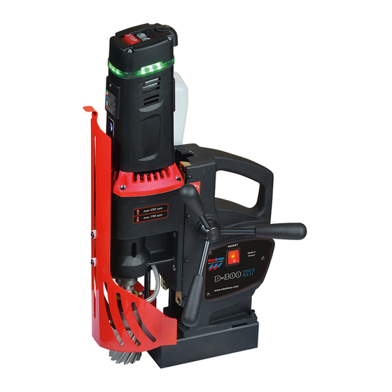
(left rotation, only to retract the tap) Motor START (right rotation) Bottle valve lever Carrying handle Motor STOP Signal LED Feed shaft Gear switch Chip guard Hole for a safety strap Electromagnetic base (MAGNET) switch Electromagnetic base D300XT Operator’s Manual... -
Page 7: Safety Precautions
17. Use annular cutters without the pilot pin only when you drill incomplete through holes. Do not use arbors without a spring. 18. Do not make holes/threads whose diameter or depth differ from those specified in the technical data. 19. Do not use near flammable materials or in explosive environments. D300XT Operator’s Manual... - Page 8 34. If you are not going to use the machine for an extended period, put anti-corrosion material on the steel parts. D300XT Operator’s Manual...
-
Page 9: Startup And Operation
To do this, lift the motor to the maximum and continue in the sequence that follows. 2 (20 mm, 0.8″) 3 (30 mm, 1.2″) 6 (30 mm, 1.2″) 7 (20 mm, 0.8″) D300XT Operator’s Manual... -
Page 10: Installing And Removing The Arbor, Mt3 Twist Drill Bit, Or Tap Chuck
Use gloves to put the arbor (drill bit, tap chuck) into the spindle (3). Make sure that the stop rod is between the pin and the fitting (4). If the arbor (tap chuck) has a nut (5), tighten the nut to the spindle. D300XT Operator’s Manual... - Page 11 (1), remove the nut. Next, lift the motor and rotate the spindle (2) to align the holes in the spindle and gearbox (3). Put the drift into the hole (4). Next, hold the carrying handle with one hand and hit the drift with a mallet (5). D300XT Operator’s Manual...
-
Page 12: Installing And Removing The Annular Cutter
(1). Use a dry cloth to clean the cutter. Put the cutter into the arbor (2) to align the flat surfaces (3) with the screws (4). Use the 5 mm hex wrench to tighten the screws. To remove the cutter, loosen the screws (4) with the 5 mm hex wrench. D300XT Operator’s Manual... -
Page 13: Installing And Removing The Screw Tap
Install the tap chuck as described before. Next, put the screw tap into the correct adapter (1). Install the adapter into the tap chuck (2). To remove the screw tap, unlock it and remove from the adapter. D300XT Operator’s Manual... -
Page 14: Installing And Removing The Cooling System
Attach the bottle to the bracket (1). Put the hose with the spring (2) between the stop rod and the body (3). Then, attach the hose to the fitting and move the spring to the arbor (4, 5). To remove the bottle, continue in reverse sequence. D300XT Operator’s Manual... -
Page 15: Preparing
Make sure that the strap is tight and not twisted. If the machine comes loose from the workpiece and hangs on the strap, replace the strap. Do not put the strap into the buckle from the front. D300XT Operator’s Manual... - Page 16 The coolant should fill the system and start flowing from the cutter. The cooling system works by gravity. Thus, in the horizontal position, rotate the bottle. In the inverted position, use coolants under pressure or in the form of spray or paste. D300XT Operator’s Manual...
-
Page 17: Drilling
When you use an annular cutter, drill only through holes. For incomplete through holes do not use the pilot pin. Incomplete through holes Complete through holes Keep the machine in the same position until the hole is made. D300XT Operator’s Manual... - Page 18 If an overload occurs, the machine stops. The overload can be caused by not enough cooling, dull tool, too fast feed, or too slow speed. Then, to start the machine again, retract the tool from the workpiece, press STOP and then D300XT Operator’s Manual...
-
Page 19: Thread Cutting
After the work is finished and the motor turned off, set the gear switch to the opposite position. Start the motor and let it operate for a while with no load to improve lubrication. Next, turn off the motor and the base, and then unplug the power cord. D300XT Operator’s Manual... -
Page 20: Adjusting The Gibs
(2). Then, lightly tighten the screws (3) so that they touch the gib. Move the motor up and down and adjust the screws (3) so that the travel is smooth. Next, tighten the screws (4) and then tighten the nuts (5). D300XT Operator’s Manual... -
Page 21: Replacing The Motor Brushes
(1). Lift the spring (2) and remove the brush. If the brush is shorter than 5 mm (0.2″), replace the two brushes with new ones. Install in reverse sequence. Then, let the motor operate with no load for 20 minutes. D300XT Operator’s Manual... -
Page 22: Accessories
D300XT 4. ACCESSORIES 4.1. Pressure cooling system Capacity of 2 liters. Part number: UKL-0440-16-00-00-0 4.2. Arbor MT3 × 32 mm Weldon Required when drilling diameter is more than 60 mm (2.3″). Part number: UCW-0563-22-00-00-0 D300XT Operator’s Manual... -
Page 23: Pipe Attachment Dmp 251
D300XT 4.3. Pipe attachment DMP 251 For pipes with diameters of 80–250 mm (3–10″). Internal dimensions: 95×211 mm (3.74″ × 8.31″). Part number: PDS-0111-03-00-01-0 D300XT Operator’s Manual... -
Page 24: Mt3 Tap Chuck × 19 Mm With Adapter
Screw tap size (metric) Adapter Ø19 without clutch WKL-000069 WKL-000070 WKL-000071 Screw tap size (metric) Adapter Ø19 with clutch WKL-000095 WKL-000098 WKL-000099 Screw tap size (imperial) Adapter Ø19 without clutch 5/16″ WKL-000167 3/8″ WKL-000168 7/16″ WKL-000169 1/2″ WKL-000170 9/16″ WKL-000171 D300XT Operator’s Manual... -
Page 25: Mt3 Tap Chuck × 31 Mm With Adapter
Requires an adapter that matches the size of the screw tap. Screw tap size Adapter Ø31 Adapter Ø19 without clutch without clutch (metric) WKL-000072 WKL-000069* WKL-000073 WKL-000070* WKL-000074 WKL-000071* WKL-000075 – WKL-000076 – WKL-000077 – WKL-000078 – * Requires a 31×19 mm reduction adapter (RDC-000008) D300XT Operator’s Manual... - Page 26 WKL-000139 WKL-000133* 3/8″ WKL-000140 WKL-000134* 7/16″ WKL-000141 WKL-000135* 1/2″ WKL-000142 WKL-000136* 9/16″ WKL-000143 WKL-000137* 5/8″ WKL-000144 – 11/16″ WKL-000145 – 3/4″ WKL-000146 – 13/16″ WKL-000147 – 7/8″ WKL-000148 – * Requires a 31×19 mm reduction adapter (RDC-000008) D300XT Operator’s Manual...
-
Page 27: Declaration Of Conformity
2.5 MM HEX WRENCH DZW-0212-12-00-00-0 SPOKE HANDLE ASSY SKR-000017 UCW-0686-07-00-00-0 ARBOR ASSY AMT2-C-19/2-2 PRS-000017 EXTERNAL RETAINING RING 25z PDK-0234-00-09-00-0 WASHER II PRS-000105 SEAL O-RING 25.2x3 TLJ-0284-00-07-00-1 COOLING SLEEVE KNC-0234-00-10-00-0 CONNECTOR PRT-0151-06-13-00-7 ROD L=35 KRP-0686-07-01-00-0 ARBOR BODY AMT2-C-19/2-2 D300XT Operator’s Manual... - Page 28 Q-TY WKR-000032 HEX SOCKET SET SCREW WITH FLAT POINT SPR-0154-00-03-00-0 SPRING WYP-0154-00-02-00-0 PLUNGER USZ-0140-05-04-00-0 SEAL PDK-0139-00-04-00-0 WASHER 18.8x10x1 PRS-000009 INTERNAL RETAINING RING 19 14 15 ITEM PART NUMBER DESCRIPTION SLN-0600-01-00-00-0 MOTOR – 115V SLN-0600-01-00-00-1 MOTOR – 230V D300XT Operator’s Manual...
- Page 29 POWERCORD 230V WITH STRAIN RELIEF ASSY (AUSTRALIA) (W8) PWD-0600-08-04-00-0 POWERCORD 230V WITH STRAIN RELIEF ASSY (INDIE) (W8) PWD-0600-08-05-00-0 POWERCORD 230V WITH STRAIN RELIEF ASSY (UK) (W8) DLW-000007 CABLE GLAND WITH STRAIN RELIEF PG13.5 PWD-0563-10-00-00-0 GROUNDING WIRE SET * not shown in the drawing D300XT Operator’s Manual...
- Page 30 D300XT 22 23 ITEM PART NUMBER DESCRIPTION WKR-000529 TORX PAN HEAD SCREW 4x50 PKR-0563-01-06-00-0 STATOR COVER ASSY PKT-0563-01-06-04-0 POTENTIOMETER KNOB PTN-000039 POTENTIOMETER D300XT Operator’s Manual...
- Page 31 MOTOR COVER WITH STATOR ASSY – 230V WZK-0563-01-06-07-0 POTENTIOMETER WIRE SET (W6) WZK-0563-01-11-00-0 LED WIRE SET (W4) WZK-0563-01-12-00-0 CONTROLLER WIRE SET (W2) PWD-0563-01-13-00-0 BRUSH HOLDER WIRE (W14) PWD-0563-09-02-00-0 CONTROLLER WIRE SET (W12) PWD-0563-09-03-00-0 CONTROLLER WIRE SET (W13) * not shown in the drawing D300XT Operator’s Manual...
- Page 32 D300XT ITEM PART NUMBER DESCRIPTION WLK-0630-02-02-00-0 CLUTCH SHAFT ASSY PDK-0211-00-16-00-0 WASHER 8,1x13x1 D300XT Operator’s Manual...
- Page 33 BALL BEARING 30x62x16 WRZ-0600-02-02-00-0 SPINDLE PRS-000035 INTERNAL RETAINING RING 62w SRB-000105 HEX SOCKET HEAD CAP SCREW M6x14 LST-0600-02-01-02-0 GEAR RACK KLK-000047 DOWEL PIN 5n6x16 SRB-000117 HEX SOCKET HEAD CAP SCREW M6x25 SMR-000001 GREASE * not shown in the drawing D300XT Operator’s Manual...
- Page 34 D300XT WIRING DIAGRAM D300XT Operator’s Manual...
- Page 35 D300XT ELECTRONIC CONTROL UNIT ASSY D300XT Operator’s Manual...
- Page 36 PROMOTECH sp. z o.o. ul. Elewatorska 23/1 15-620 Białystok Poland We declare with full responsibility that: D300XT Drilling Machine with Electromagnetic Base is manufactured in accordance with the following standards: • EN 60745-1 • EN 55014-1 • EN ISO 12100 and satisfies the regulations of the guidelines: 2014/30/EU, 2014/35/EU, 2006/42/EC, 2011/65/EU, 2012/19/EU.
-
Page 37: Warranty Card
7. WARRANTY CARD WARRANTY CARD No... ……………………….. in the name of Manufacturer warrants the D300XT Drilling Machine with Electromagnetic Base to be free of defects in material and workman- ship under normal use for a period of 12 months from the date of sale.
Need help?
Do you have a question about the D300XT and is the answer not in the manual?
Questions and answers