Table of Contents
Advertisement
Quick Links
Download this manual
See also:
Operator's Manual
Advertisement
Table of Contents

Related Manuals for SteelMax D1 PRO


Summary of Contents for SteelMax D1 PRO
- Page 1 The tools of innovation. OPERATOR’S MANUAL DRILLING MACHINE WITH ELECTROMAGNETIC BASE 15335 E. Fremont Drive, Centennial, CO 80112 1– 87STEELMAX, FAX 303 – 690 – 9172 www.steelmax.com sales@steelmax.com...
-
Page 2: Table Of Contents
Contents 1. GENERAL INFORMATION ....................3 1.1. Application ......................... 3 1.2. Technical data......................3 1.3. Design ........................4 1.4. Equipment included ....................5 2. SAFETY PRECAUTIONS ....................6 3. STARTUP AND OPERATION ................... 8 3.1. Installing and removing the arbor ................8 3.2. -
Page 3: General Information
1. GENERAL INFORMATION 1.1. Application The D1 PRO is a drilling machine with electromagnetic base, designed to drill holes either with diameters of up to 40 mm (1.57’’) to a depth of up to 51 mm (2’’) using annular cutters or with diameters of up to 16 mm (0.63’’) to a depth of up to 51 mm (2’’) using twist drill bits. -
Page 4: Design
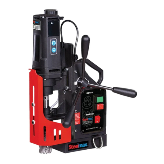
Cooling system bottle Bottle valve lever Spoke handle Feed shaft Carrying handle Control panel Motor START Arbor Motor STOP Chip guard Electromagnetic base Electromagnetic base ON/OFF switch Lug for safety chain Fig. 1. View of the D1 PRO D1 PRO Operator’s Manual... -
Page 5: Equipment Included
D1 PRO 1.4. Equipment included The D1 PRO is supplied including the following elements. Drilling machine (including arbor 1 unit with 19 mm Weldon tool holder) Metal box 1 unit Spoke handle 3 unit Cooling system 1 unit 1 m (3 ft) safety chain 1 unit 2.5 mm hex wrench... -
Page 6: Safety Precautions
Never use arbors without a spring. 18. Never use near flammable liquids or gases, or in explosive environments. 19. Using the machine on surfaces that are rusty, covered with a thick paint layer, uneven, or not rigid is prohibited. D1 PRO Operator’s Manual... - Page 7 32. Never leave the machine unattended during operation. 33. Remove from the worksite and store in a secure and dry location when not in use, previously removing the tool from the holder. D1 PRO Operator’s Manual...
-
Page 8: Startup And Operation
3 with the flats 4, and then use the 3 mm hex wrench to tighten both set screws. To remove the arbor, loosen the screws 3 using the 3 mm hex wrench. Fig. 2. Installing the arbor D1 PRO Operator’s Manual... -
Page 9: Installing, Removing, And Operating The Annular Cutter
Next, place the cutter into the arbor (2) in such a way to align the flats 3 with the set screws 4, and then use the 4 mm hex wrench to tighten both set screws. To remove the cutter, loosen the screws 4 using the 4 mm hex wrench. Fig. 3. Installing the annular cutter D1 PRO Operator’s Manual... - Page 10 Annular cutters are designed to make only through holes shown in Fig. 5. When drilling incomplete through holes the pilot pin must not be used. Incomplete through holes Complete through holes Fig. 5. Types of holes to make with annular cutters D1 PRO Operator’s Manual...
-
Page 11: Installing And Removing The Cooling System
Hang the cooling system bottle on the screws (1, Fig. 6), and then attach the bottle hose to the hose fitting (2). To remove the bottle, proceed in reverse order. Fig. 6. Installing the cooling system D1 PRO Operator’s Manual... -
Page 12: Control System Of The Electromagnetic Base Holding Force
D1 PRO 3.4. Control system of the electromagnetic base holding force The D1 PRO drilling machine incorporates a holding force control system to monitor the clamping of the electromagnetic base to the surface. The force value depends on several factors, such as type, thickness, flatness, and roughness of the surface, presence of paint, rust, or other contaminants, fluctuations of supply voltage, and the wear of the electromagnetic base bottom. - Page 13 The fluid should fill the system and begin flowing from the inside of the cutter. Because the cooling system works by means of gravitation, use a cooling paste when working in horizontal or inverted positions. D1 PRO Operator’s Manual...
-
Page 14: Drilling
Tighten the bottle cap, close the valve, and then press the pilot pin to expel the coolant remaining within the cooling system. Before inserting the machine into the tool box, remove the bottle, and then wear gloves to remove the tool from the holder. D1 PRO Operator’s Manual... -
Page 15: Adjusting The Gib Clearance
Then, use the 8 mm combination wrench to tighten the nuts (4), while countering the set screws using the 2.5 mm hex wrench (5). Fig. 8. Adjusting the gib clearance D1 PRO Operator’s Manual... -
Page 16: Replacing The Motor Brushes
To install brushes, proceed in reverse order. Place the terminal of the brush wire 5 between the washer 6 and the terminal of the motor wire 7. After the replacement, run the motor without load for 20 minutes. Fig. 9. Replacing the brushes D1 PRO Operator’s Manual... -
Page 17: Accessories
D1 PRO 4. ACCESSORIES 4.1. Pressure cooling system Capacity of 2 liters. Part number: UKL-0440-16-00-00-0 4.2. Quick change arbor 14.28 mm Weldon x 19 mm Weldon Part number: UCW-0260-13-00-00-0 D1 PRO Operator’s Manual... -
Page 18: Drilling Chuck Adapter 14.28 Mm Weldon X 1/2'' 20 Unf
4.3. Drilling chuck adapter 14.28 mm Weldon x 1/2’’ 20 UNF Part number: TLJ-0197-10-00-03-0 4.4. Drilling chuck 1/2’’ 20 UNF x 1.5–13 mm Part number: UCW-000059 4.5. Pipe attachment DMP 250 Designed for pipes with diameters of 80–250 mm (3–10’’). Part number: PDS-0110-10-00-01-0 D1 PRO Operator’s Manual... -
Page 19: Pipe Attachment Dmp 501
D1 PRO 4.6. Pipe attachment DMP 501 Designed for pipes with diameters of 150–500 mm (6–20’’). Part number: PDS-0111-03-00-01-0 D1 PRO Operator’s Manual... -
Page 20: Wiring Diagram
D1 PRO 5. WIRING DIAGRAM D1 PRO Operator’s Manual... -
Page 21: Exploded Drawings And Parts List
DZW-0140-04-00-00-0 SPOKE HANDLE ASSY LNC-0129-80-01-00-0 SAFETY CHAIN SKR-0264-00-00-00-0 METAL BOX UKL-0399-11-00-00-0 COOLING SYSTEM KLC-000005 2.5 MM HEX WRENCH KLC-000003 8 MM COMBINATION WRENCH OPK-000001 TOOL CAN KLC-000006 3 MM HEX WRENCH KLC-000007 4 MM HEX WRENCH D1 PRO Operator’s Manual... - Page 22 HEX SOCKET ROUND HEAD SCREW WITH FLANGE M5x25 NKR-000013 HEX NUT M4 PDK-000043 SPRING WASHER 4.1 DLW-000005 SNAP BUSHING WKR-000113 CROSS RECESSED OVAL COUNTERSUNK HEAD SCREW M4x16 WLK-0140-04-01-00-1 PINION SHAFT PAS-0212-00-23-00-1 D-RING STRAP KRP-0260-05-00-00-0 BODY ASSY PDS-0293-00-00-00-0 ELECTROMAGNETIC BASE D1 PRO Operator’s Manual...
- Page 23 SPRING WASHER 6.1 SRB-000113 HEX SOCKET HEAD CAP SCREW M6x20 STR-0257-04-03-00-2 ELECTRONIC CONTROLLER SW-30M 230V STR-0257-04-03-00-3 ELECTRONIC CONTROLLER SW-30M 120V FLT-0257-04-12-00-1 INTERFERENCE ELIMINATOR MSK-0291-04-01-00-0 PANEL PLATE ASSY PNK-000013 MAGNET SWITCH WLC-000007 SWITCH START-STOP 230V WLC-000005 SWITCH START-STOP 120V D1 PRO Operator’s Manual...
- Page 24 D1 PRO D1 PRO Operator’s Manual...
- Page 25 WLK-0271-02-03-01-1 PINION SHAFT z=9 KOL-0279-02-02-02-0 GEAR z=33 LOZ-000072 BALL BEARING 9x26x8 KOL-0279-02-01-03-0 GEAR z=47 PDK-0279-02-01-04-0 GEAR WASHER 17x24x0.5 KRP-0291-02-01-01-1 GEAR BOX WLK-0291-02-01-05-0 SPINDLE SHAFT KLK-000033 DOWEL PIN 4n6x12 LOZ-000027 BALL BEARING 17x35x10 LOZ-000046 BALL BEARING 20x42x12 D1 PRO Operator’s Manual...
- Page 26 INTERNAL RETAINING RING 32w PDK-000111 SPRING WASHER 4.2x0.5 WKR-000253 CROSS RECESSED PAN HEAD SELF-TAPPING SCREW 4.8x38 WKR-000423 PAN HEAD SHEET METAL SCREW 4.8x38 LOZ-000096 BALL BEARING 32x12x10 LOZ-000095 BALL BEARING 22x7x7 SMR-000001 GREASE LUBRIPLATE BP1 0.045 kg D1 PRO Operator’s Manual...
-
Page 27: Declaration Of Conformity
PROMOTECH sp. z o.o. ul. Elewatorska 23/1 15-620 Białystok Poland declare with full responsibility that: D1 PRO Drilling Machine with Electromagnetic Base is manufactured in accordance with the following standards: • EN 60745-1 • EN 55014 • EN ISO 12100 : 2004/108/EC, 2006/95/EC, 2006/42/EC. -
Page 28: Quality Certificate
D1 PRO 8. QUALITY CERTIFICATE Machine control card D1 PRO Drilling Machine with Electromagnetic Base □ 120 V □ 230 V Serial number ........................ Spindle radial runout ...................... Slide to base travel perpendicularity ................Spindle axis to base perpendicularity ................ -
Page 29: Warranty Card
WARRANTY CARD No.................. in the name of Manufacturer warrants the D1 PRO Drilling Machine with Electromagnetic Base to be free of defects in material and workmanship under normal use for a period of 12 months from the date of sale. - Page 30 21mm 0.8268 SM-AC-21-M-1 SM-AC-21-M-2 22mm 0.8661 SM-AC-22-M-1 SM-AC-22-M-2 23mm 0.9055 SM-AC-23-M-1 SM-AC-23-M-2 24mm 0.9449 SM-AC-24-M-1 SM-AC-24-M-2 25mm 0.9843 SM-AC-25-M-1 SM-AC-25-M-2 26mm 1.0230 SM-AC-26-M-1 SM-AC-26-M-2 28mm 1.1020 SM-AC-28-M-1 SM-AC-28-M-2 29mm 1.1410 SM-AC-29-M-1 SM-AC-29-M-2 31mm 1.2200 SM-AC-31-M-1 SM-AC-31-M-2 D1 PRO Operator’s Manual...
Need help?
Do you have a question about the D1 PRO and is the answer not in the manual?
Questions and answers