Table of Contents
Advertisement
Quick Links
Advertisement
Table of Contents

Related Manuals for WAGNER ZR26-I


Summary of Contents for WAGNER ZR26-I
- Page 1 Operating Manual Thread Cutting Head ZR26-I Article-No. 74424300...
-
Page 2: Table Of Contents
Choice of the infeed The coolant Maintenance 16.1. Disassembling 16.2. Mounting 16.3. Verifying of the mode of operation 16.4. Exploded assembly drawing ZR 26-I 16.5. Spare parts list of WAGNER® Cutting Head ZR 26-I Defects and causes thereof Operating Manual ZR 26-I... -
Page 3: Preface
The cutting heads of our company are widely known for their high quality and long- life cycle.We do hope that you are perfectly satisfied with our products, too. Customer care even after purchase: This operating manual helps you to make the first steps with the new WAGNER pro- ®... - Page 4 Preface We cannot hold liable for any use of components which are not manufactured or not Limitation of liability: approved by WAGNER ® Please note: Use this pro- We cannot hold liable for damages occurring through removing of safety devices of duct only for the purpose it the machine.
-
Page 5: Security Advice
Security advice Security advice • Persons operating, maintaining or servicing the cutting head should always read and understand the operating manual in particular the safety inst- ructions. Persons under the influence of alcohol and /or drugs may cause accidents! • Take into account the weight of the thread cutting head upon installation. -
Page 6: Product Description
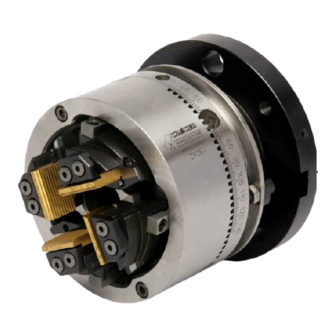
The coolant for internally cooled tools is supplied via the adapter or centrally via the connecting rod. thread cutting head chaser holder with chasers flank coupling for rod Figure 1: Main components of thread cutting head ZR26-I Operating Manual ZR 26-I... - Page 7 Product description We will deliver the matching connecting bead for the machine and the fitting for the connecting rod with the thread cutting head. The thread head offers all the mecha- nical motional processes. Through axial switching of the unit »guide ring and excentric ring« on the base body, the chaser system will be triggered by the chamfers of the excentric ring and the sli- ding pieces of the chaser holders.
-
Page 8: Chaser Holders
Chaser holders Chaser holders 4.1. Tasks The chaser holders function as a die for the chasers to mount them as cutting de- vice. They are thus designed that you may cut various threads within a certain range of diameter- and lead angle with only one set of holders. Please refer to the table of threads and holders on the pages 19 to 20 for more in- formation concerning the suitable types of holders for the threads. -
Page 9: Chasers
Chasers Chasers 5.1. Tasks The actual chipping tool is the chasers. They are fitted with a plain thread profile which means threads with various diameters Thread- and holder tables: and the same lead can be cut with just one set see page 19 to 20 of holders. - Page 10 Chasers First cut short: For workpieces with a thread against the collar and short thread run out Thread run out approximately 2 x lead. First cut medium: For workpieces without or little oversize, blank or preturned Thread run out approximately 3 x lead. First cut long: For workpieces made of rolled material or with oversize.
-
Page 11: Polished Section Of The Chaser
® As cup wheels we do recommend conical cup wheels EKW 60 Jot with edge reinforce- ment. They are available from WAGNER ® When grinding chasers with low thread profiles it is very useful to adjust an illumina- ted magnifier at the grinding device. - Page 12 Chasers In special cases for instance steels with low strength (e.g. elastic limit 37) stainless steel, copper or aluminium it might be better not to grind the chip surface as a plain area but to grind a radius. This radius the so-called undercut enables the discharge of chips here.
- Page 13 Chasers Cutting angle Example: throat angle: 18° (medium) cutting angle: 15° This results in an additional angle of 2.6° Aside from these methods of determination the grinding angle can be always che- cked in the setting device. The cutting edge of the chasers should be parallel to the foot switch of the flowmeter which runs parallel to the axis of the workpiece.
- Page 14 Chasers The chasers are looped in on the face side according to the set angles. Grinding with guiding presser foot : See figure 10.2 and 10.4. The grinding process is divided in two work steps: Grinding of the guiding presser foot: The guiding presser foot is looped in.
-
Page 15: Equipment
Equipment Equipment 6.1. The fixture The fixture is used to mount the chasers to enable an accurate grinding of the chasers. Figure 11: Fixture for chasers 6.2. The setting device The setting device is used to set the chasers in the chaser holder to the value needed for the thread to be cut. -
Page 16: Setting Of The Chasers In The Chaser Holder
Setting of the chasers in the chaser holder Setting of the chasers in the chaser holder In order to cut proper threads it is essential to set the chasers evenly in the approp- Thread- and holder riate chaser holders according to the holder table and in the right proportion to the tables: see page 19-20 workpiece. - Page 17 Setting of the chasers in the chaser holder The established value from the following table has to be added to the setting value from the holder table. This value is dependent on the material to cut. Material or shape of the workpiece Loading in % from thread diameter Machining steel 1 - 2...
- Page 18 Setting of the chasers in the chaser holder Threads M10 x 1 Material 9S 20 K Setting value from holder table 0.60 + 1.5 % from diameter 10 0.15 Setting value of the chaser + 0.75 Please note: Adjust the chasers carefully! Set them up to that point until you won’t notice the brinelling of the thread anymore.
-
Page 19: Holder Tables
Setting of the chasers in the chaser holder 7.2. Holder tables Metric threads DIN 13 External threads, tolerance 6g Tools setting value Thread Pitch External diameter Flank diameter Minor diameter Chaser holder Chaser indication [mm] size maxi- minimum maxi- minimum maxi- minimum Type... - Page 20 Setting of the chasers in the chaser holder Cylindrical Whitworth pipe threads DIN 259 (ISO 228-1 External threads, tolerance 6g Tools setting value Thread Lead External Flank diameter Minor diameter Chaser holder Chaser indication [turn/ diameter size 1 inch max. min.
-
Page 21: Insertion And Setting Of The Chasers
Setting of the chasers in the chaser holder Fine threads UNF 7/16 - 20 11,079 10,874 10,254 10,247 9,522 ZR26/D-2,5 KD 6,9 - 14,7 744 270 00 S 02 3,94 ½ - 20 12,667 12,461 11,841 11,732 11,110 ZR26/D-2,5 KD 6,9 - 14,7 744 270 00 S 02 3,85... -
Page 22: Installation Of The Chaser Holders
Installation of the chaser holders Installation of the chaser holders To install the chasers holders with the set chasers into the cutting head, push back the guiding ring with excentric ring towards the flange thus far so that the holder is swivelling in the holder guidance The chaser holders are inserted in base body boreholes and are swivelled in the holder guiding. -
Page 23: Presetting Of The Thread Diameter
Presetting of the thread diameter Presetting of the thread diameter The approximate diameter of the thread to cut is set by twisting of the excentric ring. The setting is continuous. However, should the gear segments be inserted as locking devices of the diameter, please take their regrading into consideration. The adjustment of the thread diameter resp.the fine adjustment is done by the con- Fine adjustment of the necting rod. -
Page 24: Mounting Of The Cutting Head Onto The Machine
Mounting of the cutting head onto the machine 10. Mounting of the cutting head onto the machine The thread cutting head ZR 26 I is usually mounted rotating with stagnant workpiece. However, it can be mounted stagnant with rotary workpiece, too. In addition to the thread cutting head, we deliver the suitable mounting flange for the machine and the connector for the connecting rod. -
Page 25: Operation Sequence Of The Thread Holders
Operation sequence of the thread holders 11. Operation sequence of the thread holders Home position: The closed thread cutting head is positioned in front of the workpiece. Thread cutting: The feed unit moves the rotating cutting head according to the flank lead along the workpiece. -
Page 26: Control Paths
Control paths 12. Control paths Please refer to chart 00366569 on page 27 for the required control paths. A brief description hereto: Position: "Head closed (max.)": The connecting rod is in its foremost position; the cutting head is completely closed. Another operation in direction +Z isn’t possible. - Page 27 Control paths Control chart 00366569 Operating Manual ZR 26-I...
-
Page 28: Thread Cutting And Diameter Fine Adjustment
Thread cutting and diameter fine adjustment 13. Thread cutting and diameter fine adjustment When presetting the cutting head the diameter is set too little, intentionally. Due to the twisting of the excentric ring. Thus we recommend correcting the position of the con- necting rod within the section A in Z (-) before cutting the first thread. -
Page 29: Cutting Speed
Cutting speed 14. Cutting speed 14.1. Choice of the cutting speed The following values are approximate values which are referred to as a basis for sharp threads. Crucial factors for the choice of the cutting speed are apart from the workpiece, the strength of the die clamping and the unclamping- and the machining length. -
Page 30: The Coolant
The coolant 15. The coolant A cooling lubricant has to be used when thread cutting. We recommend using water-soluble bore oil. Even better is cutting oil as it enhances the cutting process and the thread surface. In special cases we recommend to contact the manufacturing company. -
Page 31: Maintenance
Maintenance 16. Maintenance It is necessary to maintain this precision tool for ensuring its operation and perfor- mance. The maintenance intermittent is dependent on the operating conditions. The mode of operation and the condition of the cooling lubricant are hereby most impor- tant. -
Page 32: Verifying Of The Mode Of Operation
Maintenance Insert the two O-rings [420] into the corresponding counter bores of the flank [400]. Now attach the flank on the base body [10] so that the location bolt fits into the cor- responding bores of the base body. Flank [400] and base body [10] are screwed together by using the four cylinder head screws [130]. -
Page 33: Exploded Assembly Drawing Zr 26-I
Maintenance 16.4. Exploded assembly drawing ZR 26-I Operating Manual ZR 26-I... -
Page 34: Spare Parts List Of Wagner® Cutting Head Zr 26-I
Maintenance 16.5. Spare parts list of WAGNER® Cutting Head ZR 26-I Thread cutting head (article no. 74424300) Part. No. Quantity Article No. Designation 744 230 00 base body ZR 26-I 744 249 00 pressure socket 033 100 63 pressure spring 1.0x5.0x20.0... - Page 35 026 770 02 screwdriver 2.5 Flank complete (article no. on request) Part. No. Quantity Article No. Designation on request flank ZR26-I 020 451 01 threaded pin M5x4 DIN 913 5822001111 o-ring 737 267 00 locating bolt, levelled Setting device (article no. 70535600) Part.
-
Page 36: Defects And Causes Thereof
Defects and causes thereof 17. Defects and causes thereof Defect characteristic Causes and remedies Multi start -or cut badly threads When mounting the order of the threads 1-2-3-4 has been disregarded. The thread turns are cut off completely The chasers have been inserted in the right order, but in the wrong direction. - Page 37 Defects and causes thereof Defect characteristic Causes and remedies Flawed lead. Holder angle and lead angle are too unequal. The feed unit runs too heavily or at the wrong speed. Uneven threads and flanks. The chaser is blunt or the cutting angle is too small.
- Page 38 +49(0) 71 27/ 97 33-90 email: info@wagner-werkzeug.de web: www.wagner-werkzeug.de Imprint This operating manual is a publication made by Wagner Tooling Systems Baublies GmbH. Information in this catalog is current as of publication date and subject to change. All rights reserved. Date: 10 | 2018...
Need help?
Do you have a question about the ZR26-I and is the answer not in the manual?
Questions and answers