
Subscribe to Our Youtube Channel
Related Manuals for Datavideo KMU-200


Summary of Contents for Datavideo KMU-200
- Page 1 4K MULTI-CHANNEL TOUCH SCREEN REGION OF INTEREST SWITCHER KMU-200 Instruction Manual...
-
Page 2: Table Of Contents
ARRANTY DISPOSAL ..........................7 CHAPTER 1 INTRODUCTION ....................8 ........................8 EATURES ......................8 YSTEM IAGRAM CHAPTER 2 CONNECTIONS TO THE KMU-200 ..............9 ....................... 9 ANEL ........................ 12 ONTROLS CHAPTER 3 OSD MENU ....................16 ....................... 16 VERVIEW CHAPTER 4 KMU-200 OPERATIONS.................. 17 .................... - Page 3 Location-Y ........................ 37 Foreground Color ..................... 37 System ......................... 38 Network Setting ....................... 40 Account and Password ..................... 40 Time Setting ......................40 Firmware Update...................... 41 Disk Format ......................41 Device Name Setting ....................42 Other Option ......................42 System Control ......................42 Status ...........................
- Page 4 Datavideo Technologies will try to give correct, complete and suitable information. However, Datavideo Technologies cannot exclude that some information in this manual, from time to time, may not be correct or may be incomplete. This manual may contain typing errors, omissions or incorrect information.
-
Page 5: Fcc Compliance Statement
AC adapter. If you are not sure of the type of power available, consult your Datavideo dealer or your local power company. 8. Do not allow anything to rest on the power cord. Do not locate this unit where the power cord will be walked on, rolled over, or otherwise stressed. -
Page 6: Warranty
Warranty Standard Warranty Datavideo equipment are guaranteed against any manufacturing defects for one year from the date of purchase. The original purchase invoice or other documentary evidence should be supplied at the time of any request for repair under warranty. -
Page 7: Disposal
Card are covered for 1 year. The three-year warranty must be registered on Datavideo's official website or with your local Datavideo office or one of its authorized distributors within 30 days of purchase. Disposal For EU Customers only - WEEE Marking This symbol on the product or on its packaging indicates that this product must not be disposed of with your other household waste. -
Page 8: Chapter 1 Introduction
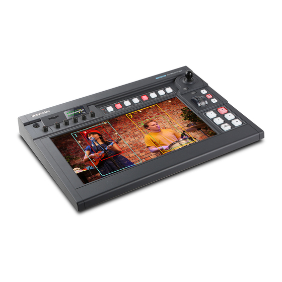
Chapter 1 Introduction The KMU-200 4K Multi-Channel Touch Screen Region of Interest is a single unit that allows you to convert the 4K input from the connected camera to the 1080 HD output. The channel buttons select the Program Channel output as well as the Preview. The joystick and knob adds greater flexibility to Pan, Tilt and Zoom controls of the selected frame. -
Page 9: Chapter 2 Connections To The Kmu-200
Chapter 2 Connections to the KMU-200 In this section, you will be provided with general overviews of the rear panel as well as the control panel. 2.1 Rear Panel This section provides brief descriptions of various connection ports on the rear panel. - Page 10 PC IN Connect a PC or laptop. PC LOOPOUT Connect a monitor for displaying PC IN video. AUX Output The AUX port outputs one of Channel 1/2/3/4 videos, which can be set in menu. PGM Output The PGM port outputs one of Channel 1/2/3/4 videos, full screen of the image captured by the camera and PC IN view.
- Page 11 RTMP. See Chapter 5 Video Streaming and Recording for detailed descriptions. Control DVIP/Control Firmware Upgrade FW Upgrade Connect the KMU-200 to a laptop/PC via a mini- USB-to-USB cable to perform a firmware upgrade. See Appendix 1 Firmware Upgrade more details.
-
Page 12: Controls
2.2 Controls This section provides an overview of various functions of the control panel. Output Selections Channel Button Group This button group allows you to select what you would like to display on the PGM Output. Buttons 1 – 4 correspond to Channels 1 – 4. Press the Full Screen button to display the entire image captured by the camera connected to 4K HDMI IN port. - Page 13 Pan / Tilt Control P/T Joystick PAN – Move the joystick left or right to pan the selected frame from left to right or vice versa. TILT – Move the joystick up or down to tilt the selected frame up or down. Note: Before attempting to use the joystick to PAN or TILT the frame, first make sure the PTZ LOCK button is not enabled.
- Page 14 Note that you should only use Class 10 SD card or above. See the Appendix, Recommended SD Cards, for a list of SD cards recommended by Datavideo. Note: Do not remove SD card while recording is in progress as doing so may result in corrupted video files.
- Page 15 CH1: Balanced MIC 1 IN CH 2: Balanced MIC 2 IN AUX: RCA audio input (analog) Digital: HDMI audio input (digital) Master: PGM audio output MASTER OUT Meter The LED style meters show the audio signal strength at the Main Program Audio Output.
-
Page 16: Chapter 3 Osd Menu
Chapter 3 OSD Menu The KMU-200 can be configured via an on screen menu. To open the OSD menu, slide two fingers down on the touch screen. Slide two fingers up on the touch screen to close the OSD menu. To select a particular option, simply tap on the corresponding item on the touch screen. -
Page 17: Chapter 4 Kmu-200 Operations
KMU-200 Operations 4.1 Channel Buttons After the KMU-200 is powered ON, you will only see one channel button illuminated red, indicating that particular channel is the program channel (on air) and the button corresponding to the preview channel should illuminate green. If you only see one channel button illuminated red and the rest of the channel button LEDs are off, program and preview channels share the same channel. -
Page 18: Touch Screen
You can also move the channel frame to the desired image point and at the same time to allow the KMU-200 to change the channel frame size to a small or large frame. The steps are outlined as follows:... - Page 19 2. Tap the touch screen with three fingers such that only the Program Channel is shown on the touch screen. Note: You can also slide down with three fingers to show the Program Channel only; slide down with three fingers to show all four channels. 3.
-
Page 20: Chapter 5 Video Streaming And Recording
1. Connect the NVS-31 MARK II’s stream port to the network via an Ethernet cable. 2. Turn on the KMU-200’s power and the NVS-31 MARK II will also be turned ON in the DHCP mode by default. 3. Connect the laptop to the same network that the NVS-31 MARK II is connected to and download the free IP Finder utility program. -
Page 21: Connecting To A Non-Dhcp Network (Static Ip)
1. Connect the NVS-31 MARK II’s stream port to the network via an Ethernet cable. 2. Turn on the KMU-200’s power and the NVS-31 MARK II will also be turned ON in the DHCP mode by default. 3. Search for the NVS-31 MARK II device according to the method as detailed in the previous DHCP section. -
Page 22: Troubleshooting The Network Connection
Tip: If you forget or lose the IP address, do the following to reset the network settings. Turn off the device. Press the RECORD and STREAM buttons at the same time then turn ON the power of the device ... - Page 23 Click START located at the bottom left corner of your screen. On the text bar, enter Network Connections then click the icon that appears. Double click the network adapter that connects your PC or laptop to the network. ...
- Page 24 Reconnect the PC and the NVS-31 MARK II to the network. Restore the PC’s original network settings. Shut down the KMU-200; wait for approximately five seconds before turning the KMU- 200 back ON. You should be able to access the NVS-31 MARK II through the fixed IP address.
-
Page 25: Advanced Troubleshooting
HS device. MAC address starts with 00:07:36:03:xx:xx. Device’s MAC address starts with 00:07:36:07:xx:xx (KMU-200 and KMU-200 only) On the command prompt (terminal on MAC OS), enter "arp -a" then press enter key to display an ARP list. -
Page 26: Operation Mode
Note: The NVS-31 MARK II web UI does not update automatically so to learn the latest device status, please refresh the page manually. While monitoring streaming and recording, please update the page periodically regardless of how you operate the device (using the device’s physical buttons only or using the device’s physical buttons along with the web UI). - Page 27 Four streaming protocols available on the NVS-31 MARK II are RTSP, RTMP, HLS, and TS. See Section 5.3 for instructions on each individual stream setup. Note that once your video streams are set up, click “Apply” button to apply the new stream settings.
- Page 28 RTSP (Real Time Streaming Protocol) RTSP Port: The RTSP port number ranges from 554 to 562 and is 554 by default. RTSP HTTP Port: The RTSP HTTP port number ranges from 8553 to 8563 and is 8554 by default. ...
- Page 29 You should also be aware that higher resolutions require greater processing power to encode the stream. Attempting too high of a resolution on too little processing power can result in degraded image quality and corrupted or interrupted streams or recordings. Resolutions available for your stream encoder are listed as follows: ...
- Page 30 Encoder Mode The Encoder Mode sets the video bitrate mode for your video stream. The available modes are listed as follows: High (8M) Medium (4M) Low (2M) Tip: You can also switch between different bitrate modes by pressing the Bitrate button in the H.264 Encoder button group.
- Page 31 Level ID Max. Video Max Frame Size Max decoding speed in Resolution, Frame Rate Bitrate in in macroblocks macroblocks per (Max Stored Frames) kbits/s second 10000 1620 40500 352×480@61.4 (12) 352×576@51.1 (10) 720×480@30.0 (6) 720×576@25.0 (5) 14000 3600 108000 720×480@80.0 (13) 720×576@66.7 (11) 1,280×720@30.0 (5) 3.2 (HD)
-
Page 32: Record Mode
5 3 2 1 Record Mode The NVS-31 MARK II’s record engine allows you to record your program on the SD card. See Appendix 2 for a list of recommended SD cards. The record parameters shown in the diagram below will be discussed in detail in this section. - Page 33 Resolution Recording resolution is the number of pixels (dots) used to create an image. Higher resolutions use more pixels to create an image. This means that greater amounts of detail can be expressed in the image, but larger files sizes and a greater amount of storage (i.e. hard drive space) are required to save the images or video.
- Page 34 6M 4M 2M 1M 512K 256K Recommended video bitrates 720P or lower – 8 – 10 mbps 1080P or higher – 15 mbps or higher Encoder Mode The Encoder Mode sets the video bitrate mode for your recording. The available modes are listed as follows: ...
- Page 35 Level ID Max. Video Max Frame Max decoding speed Resolution, Frame Rate Bitrate in Size in in macroblocks per (Max Stored Frames) kbits/s macroblocks second 320×240@10.0 (3) 352×288@7.5 (2) 6000 320×240@20.0 (7) 352×288@15.2 (6) 11880 320×240@36.0 (7) 352×288@30.0 (6) 2000 11880 320×240@36.0 (7) 352×288@30.0 (6)
- Page 36 data rate as much. Depending on your applications, the NVS-31 MARK II offers the user 16 GOP sizes ranging from 1 to 255. 255 240 200 120 100 60 50 30 25 ...
-
Page 37: Cg Layer
CG Layer You are allowed to toggle the CG text or picture between four layers, from layer 0 to layer 3. CG Type You may select to place a text (Text) or graphic (Picture) CG object on your video from the drop-down menu. -
Page 38: System
System The system page allows the user to configure several network and system related settings. The network settings are DHCP enable/disable, static IP address, subnet mask, default gateway, primary and secondary DNS, and etc. The system settings are account credentials, time settings, firmware update, disk format and device name. -
Page 40: Network Setting
Network Setting In network settings, you can either manually enter the IP address or set the device to DHCP mode which allows the router to automatically assign the IP address to the NVS-31 MARK II. DHCP In DHCP mode, the router automatically assigns the IP address to the device. If you want to manually configure the network settings, disable this option. -
Page 41: Firmware Update
NTP Server If you’ve selected “Automatically from the Internet,” you will need to enter the NTP server address here. An example of the NTP server address is time.google.com. Manual If you’ve selected “Manual”, the Date and Time fields will appear showing the device’s system date and time values. -
Page 42: Device Name Setting
Device Name Setting Enter a name for this device and click Apply to save the name. Other Option Timeout Period This sets the timeout period for the current login. See below for available options. 20 Min 120 Min ... -
Page 43: Vertical
Vertical On this page, you will be able to change your stream video orientation. Crop: Designed for KMU-200 product series allowing 16:9 video output and image crop on left and right. Rotate: Designed for video production; if the camera is placed upside down, this mode will reverse it. - Page 44 VideoLAN’s official homepage (https://www.videolan.org/) and download the installation file then install the program. Follow the steps below to obtain the RTSP URL: 1. On the web UI, click “Operation Mode” “Stream” to open the stream settings page. 2. Select RTSP from Stream Type drop-down menu. 3.
- Page 45 Follow the steps below to obtain the TS URL: 1. On the web UI, click “Operation Mode” “Stream” to open the stream settings page. 2. Select TS from Stream Type drop-down menu. 3. Enter the TS URL. Note that the TS URL shown below is only for illustration purpose. 4.
- Page 46 7. As shown in the diagram below, enter the stream URL then click Play to start streaming. Follow the steps below to obtain the HLS URL: 1. On the web UI, click “Operation Mode” “Stream” to open the stream settings page. 2.
- Page 47 3. Click the Start Stream button to start the stream. 4. Based on your settings, the device will automatically generate a .m3u8 stream URL: http://192.168.1.82/hls/2/session0.m3u8 5. Enter the HLS URL into the client device. 6. Open VLC then click Open Network Stream (shown in the diagram below). 7.
-
Page 48: Rtmp
8. You can also play .m3u8 stream URL using the devices listed as follows: iPhone, iPad and MacBook: Use Safari to open the .m3u8 stream URL. Windows 10: Use Microsoft Edge to open the .m3u8 stream URL. RTMP In the RTMP mode, the NVS-31 MARK II can send up to two data streams to multiple CDNs or media servers that support the Real-Time Messaging Protocol. - Page 49 4. On the right, scroll down to the bottom where you will be able to find Server URL and Stream name/key. 5. On the NVS-31 MARK II, open the Stream operation mode page. 6. Select RTMP from the Stream Type drop-down menu. 7.
-
Page 50: Text Overlay Video
12. To stop live streaming, simply click the Stop Stream button. Text Overlay Video The KMU-200’s built-in video streaming server not only allows you to stream and record your program, it also features a CG tool that is capable of overlaying text on the video currently being broadcast. -
Page 51: Stream And Record Buttons
Y coordinate moves the overlay object up. 5.4 Stream and Record Buttons The RECORD, STREAM, VERTICAL and BITRATE buttons on the front panel of the KMU-200 give the user certain controls of the record and stream functions. In this section, we will cover operations of these four buttons in detail. -
Page 52: Stream Button
Stop recording While recording, the RECORD button is solid red. Press and hold the RECORD button for approximately 2 seconds. When the record function is terminating, the RECORD button turns from solid red, then blinking red and finally to solid white. ... -
Page 53: Restoring Factory Defaults
When the RECORD, STREAM, VERTICAL and BITRATE buttons turn solid white, it indicates that the NVS-31 MARK II’s factory defaults have been successfully restored. 5.6 Firmware Update Datavideo usually releases new firmware containing new features or reported bug fixes from time to time. See Appendix 1... -
Page 54: Chapter 6 Appendices
Note: Download the latest firmware files and update tools from the product page (https://www.datavideo.com/us/product/KMU-200#downloads). Upgrade Procedure First, connect your laptop to the KMU-200’s firmware upgrade port (mini USB) via a USB cable. Then follow the procedures below to update the respective firmware. MB: KMU-200_MB-vx.x.bin 1. - Page 55 2. Open the LM Flash Programmer. 3. In the Configuration tab, make sure “0 – Device Firmware Upgrade” is there. 4. In the Program tab, click Browse to locate the MB file “KMU-200_MB-vx.x.bin” on the local hard disk. Make sure “Reset MCU After Program” is checked before clicking the Program button.
- Page 56 3. Click the Burn button. 4. Power cycle the KMU-200. 5. The firmware upgrade process will begin as soon as the KMU-200 is turned ON again. 6. The process is complete when the Progress Bar reaches 100% and the “Firmware Update Success!”...
- Page 57 Tool has detected the COM port to which the KMU-200 is connected. II. Select Touch Panel 2. Click the Load File button to locate the firmware file “KMU-200-PL_x.x.bin” on the local hard disk. 3. Click the Burn button and the firmware upgrade process will begin.
-
Page 58: Recommended Sd Cards
Recommended SD Cards You should only use Class 10 SD card or above. In this appendix, you will find a list of SD cards recommended by Datavideo. Recommended SD Cards Brand Model Pictures Kingston SDHC I C10 SANDISK Extreme SDXC I C10 U3 V30... - Page 59 SANDISK Extreme SDHC C10 16GB ADATA Premier microSDXC I UHS-I U3 Class 10 with SD adapter 64GB SANDISK ULTRA® SDHC™/SDXC™ UHS-I 128 GB...
-
Page 60: Frequently-Asked Questions
Frequently-Asked Questions This section describes problems that you may encounter while using the KMU-200. If you have any questions, please refer to related sections and follow all suggested solutions. If problem still exists, please contact your distributor or the service center. -
Page 61: Dimensions
Dimensions All measurements in millimeters (mm) -
Page 62: Specifications
Specifications Interfaces Video Inputs 2 x HDMI (HDMI 2.0 for 4K, HDMI 1.4 for PC input) Loopout PC loopout Video Outputs 2 x HDMI (PGM, AUX) Audio Input XLR/6.3mm x2 (Mic In) , RCA x 1 pair Audio Output RCA x1 pair, HDMI embedded out Power DC 12V 5A Firmware Update... - Page 63 Sample rate : 48KHz, 16bit Storage SD Card (Class 10 above) File System FAT, NTFS, exFAT Network 10/100Mbps Ethernet TS over TCP/UDP (unicast & multicast) RTSP over HTTP/TCP/UDP (RTSP Elementary Stream) Streaming Protocols RTMP(Publish) Other Dimension (mm) 438(W) x 331(D) x 114 (H) Weight 4.258 KG...
-
Page 64: Service And Support
Jun-30.2020 Datavideo Technologies Co., Ltd. All rights reserved 2020 Version E1...
Need help?
Do you have a question about the KMU-200 and is the answer not in the manual?
Questions and answers