Table of Contents
Advertisement
Advertisement
Table of Contents

Subscribe to Our Youtube Channel
Related Manuals for Datavideo SE-2200


Summary of Contents for Datavideo SE-2200
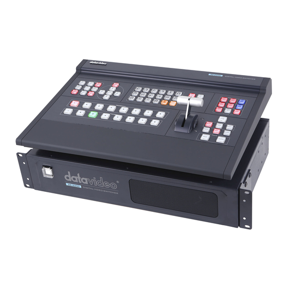
- Page 1 HD/SD 6-CHANNEL DIGITAL VIDEO SWITCHER SE-2200 Instruction manual...
-
Page 2: Table Of Contents
..................28 ORKING WITH A FIXED OR SINGLE AUDIO SOURCE ................. 29 WITCHING BETWEEN DIFFERENT EMBEDDED AUDIO SOURCES HOW TO RE-CALIBRATE THE SE-2200 T-BAR ................. 31 GPI CONNECTIONS ........................32 SE-2200 TALLY OUTPUTS ......................33 EXAMPLE SE-2200 SET UP ......................34 DIMENSIONS .......................... - Page 3 Disclaimer of Product & Services The information offered in this instruction manual is intended as a guide only. At all times, Datavideo Technologies will try to give correct, complete and suitable information. However, Datavideo Technologies cannot exclude that some information in this manual, from time to time, may not be correct or may be incomplete. This manual may contain typing errors, omissions or incorrect information.
-
Page 4: Fcc Compliance Statement
AC adapter. If you are not sure of the type of power available, consult your Datavideo dealer or your local power company. 8. Do not allow anything to rest on the power cord. Do not locate this unit where the power cord will be walked on, rolled over, or otherwise stressed. -
Page 5: Warranty
The product warranty period beings on the purchase date. If the purchase date is unknown, • the product warranty period begins on the thirtieth day after shipment from a Datavideo office. Damage caused by accident, misuse, unauthorized repairs, sand, grit or water is not covered •... -
Page 6: Connections And Controls
Main Unit – Front Panel The front panel on the SE-2200 main unit has a grille for airflow cooling fans. Please do not block or cover this grille as the unit may overheat. This grille should also be kept free of dust. The front panel can be removed by using the four thumbscrews. -
Page 7: Main Unit - Rear Panel
16. Input 5 – HD-SDI / HDMI (User Defined) Rear Panel Connections Video Inputs The SE-2200 can be supplied with up to six video input channels. The SE-2200 has six BNC input connectors and two input HDMI ports. Input channels 5 and 6 are optionally set up either as BNC SDI or HDMI. - Page 8 ITC-100 eight channel talkback system or the Datavideo TLM range of monitors. Console Port This 9pin D-Sub connector is used to connect the Control Panel / Keyboard to the rear of the SE-2200 Main Processing unit. Ethernet Port For external PC control only RS-232 / RS-422 Remote This port is not active under current firmware.
- Page 9 For firmware upgrades, switch both switches to the upper position. For Fast Start, please select lower position. Service Port This RJ45 Ethernet port is used to update the SE-2200 firmware, or upload logos and images using the SEConfig software. SDI Video Outputs The six BNC output connectors are user defined SDI outputs.
-
Page 10: Control Panel Overview
HDMI Multi-View Outputs SE-2200 Multi-view monitoring is available across two HDMI monitors. These HDMI outputs can be used to monitor video and audio in a number of different configurations. This Multi-view is supplied from the HDMI connection(s) on the rear panel. When connected to two compatible HDMI monitors a variety of multi-image layouts is possible. -
Page 11: Keyboard Controls
Black background – the black background, for use on the Program and Preset row. Background button – assigns a background colour or colour bars for use on the Program and Preset row. Note: Please enter the SE-2200 MENU and select CONSOLE SETTINGS to set the background colour. - Page 12 2. While still holding down the FS button, press the required input on the Preset row. 3. The input button will flash to confirm the Frame Store is selected. The contents of each Frame Store are uploaded to the SE-2200 from a PC. The supplied SEConfig software is used to do this.
- Page 13 AUDIO FOLLOW VIDEO section. Menu Control Press the MENU button in the SE-2200 function section to enter the System Configuration Menu. Press the UP, DOWN, LEFT, and RIGHT arrow buttons to navigate the menu options and to change values. Use the ENTER button to save...
- Page 14 WIPES The SE-2200 has 17 user defined wipe buttons, and a BDR button. All wipes can have an optional colour border applied. The wipe border width and colour are chosen within the menu system. Transitions can be performed manually using the T-Bar or automatically by using the SPEED and AUTO TAKE buttons.
- Page 15 PIP Preview and PIP Program When looking at the top right corner of the SE-2200 Control Panel / Keyboard there are four PIP keys. These are labelled Program and Preview. The upper PIP1 and PIP2 keys relate to activating Picture In Picture images on the Program outputs.
- Page 16 WIPE The WIPE button is selected when a wipe effect transition between the selected Program and Preset sources is required. This WIPE effect is produced by then moving the T-Bar manually or by pressing the AUTO TRANS button. This performs a simple immediate switch from the current main source to the selected sub source.
- Page 17 TIMER In some mixing or switching applications it is useful to have a countdown timer. It could be that the input is a pre-recorded video clip and you need to know when to be ready to switch away from it. This countdown timer function is only seen in the status area of the HDMI multi-view output near the normal Clock function.
-
Page 18: Menu Options
HDMI 1 Multi-view output. This section covers the Menu options in the order that they appear on the SE-2200 HDMI 1 Multi-view. These settings may also appear in more detail elsewhere in this instruction manual. Options may vary depending on the firmware version in use. - Page 19 PIP 2 Vertical Position 000~108 Window size 01~33 Border Width 00~35 Border Color 01~08 Logo Selection Logo 1 Logo Settings Horizontal Position 000~110 Logo 2 Vertical Position 000~124 Horizontal Position 000~110 Vertical Position 000~124 Clock Settings Set Hours 00~24 Set Minutes 00~59 Clear seconds DSK Settings...
-
Page 20: Multi Screen Modes
Multi Screen modes The SE-2200 HDMI Multi view outputs can be Multi Screen - Variant A configured using menu option 12. Multi Screen Setup. Three Multi Screen layouts are available, variant A, B or C. This Multi Screen output can also be assigned to any of the six SDI outputs using menu option 4. -
Page 21: Se-2200 Video Layers
Picture in Picture (PIP), DSK LUMA KEY and LOGOs. Before attempting to use the SE-2200’s PIP, DSK LUMA KEY and LOGO functions it may help to first understand the order of the video layers at the SE-2200 Program (PGM) outputs. -
Page 22: Picture In Picture Function
Picture in Picture Function The SE-2200 Picture in Picture function allows you to place one or two smaller PIP images over a chosen full size background image. The smaller PIP images can be set to pre-defined sizes and positioned almost anywhere within the Preset/Program screen area. These PIP windows can also have a coloured border applied, and can be brought into the production with a default PIP dissolve transition. - Page 23 4. Pressing PIP PGM will take the chosen PIP1 or PIP2 to air with a fade in transition.
-
Page 24: Dsk Function
DSK Function The SE-2200 has two Down Stream buttons (DSK PGM, DSK PVW). This means it is able to take a key source video input and replace the white or black parts of this image with the video from another source. -
Page 25: Tc-200 Mode & Cg-200 Overlay Input From A Laptop
TC-200 Mode & CG-200 overlay input from a laptop Use the SE-2200 menu option Inputs 5 and 6 mode to change input 6 from SDI input to HDMI. Use the up arrow key to select HDMI. A tick will appear. Press ENTER to save this setting. -
Page 26: Audio Function
AUDIO Function Overview The SE-2200 has a simple, cost effective, audio switcher built in. The SE-2200 has the ability to take audio from several sources either XLR analogue, SDI and/or HDMI inputs. The audio can be embedded onto the HDMI and SDI outputs and/or fed into the analogue XLR audio connections. -
Page 27: Audio Fixed
When the operator switches between the video sources, the sound of video input 1 remains on all the time. Audio Menu Options – De-embedding SDI or HDMI audio Using the following SE-2200 menu options, audio can be selected from the SDI or HDMI video inputs. Group 1,2,3 or 4 SDI INPUTS Embedded Audio... -
Page 28: Working With A Fixed Or Single Audio Source
We have two mono mics (channels 1 & 2) connected to an HD camera. These embedded audio channels are then sent from this camera along with the HD-SDI video to the SE-2200 switcher. If we want to only hear these two audio channels regardless of the video channel used then we would set... -
Page 29: Switching Between Different Embedded Audio Sources
Press the ENTER key in the MENU area of the SE-2200 keyboard to display the on screen menu and then enter AUDIO CROSSPOINTS of the AUDIO SETTINGS option. Change the de-embedded audio setup in the menu system to show a value of 1 for each video input channel. - Page 30 Follow auto audio mixing type (use above option) T-Bar Audio Mixing Type Tick selection of By the end (clean cut or immediate audio switch)
-
Page 31: How To Re-Calibrate The Se-2200 T-Bar
BK button on both the Program and Preset rows of the switcher’s keyboard. 4. Power ON the SE-2200 switcher while still holding down the buttons in step 3. 5. The switcher will start but the keyboard lights will remain dead except progress LEDs. -
Page 32: Gpi Connections
GPI switch. The interface supports both “trigger pulse” and level “Hi/ low” system. The GPI interface is a 3.5mm Jack Socket which is situated on the rear panel of the SE-2200. Contact closure between the Outer and Inner contacts on the jack plug will trigger a user selected event. -
Page 33: Se-2200 Tally Outputs
SE-2200 Tally Outputs The SE-2200 has a D-sub 25 pin female tally output Dielectric strength: Max. DC port. These connections provide bi-colour tally 24V Current: Max. 50mA information to a number of other Datavideo products, such as the ITC-100 eight channel talkback system and the TLM range of LCD Monitors. -
Page 34: Example Se-2200 Set Up
Example SE-2200 Set Up... -
Page 35: Dimensions
Dimensions... -
Page 36: Specification
Specification Connections Total Video Inputs Total 6 video inputs ( 6 SDI or 4 SDI + 2 HDMI ) Total Outputs Total 6 SDI video outputs + 2 HDMI Multi view output Multi view Out HDMI SDI Video Input Max 6 HDMI Video Input Max 2 Analog Audio Output... - Page 37 Frame store Control Panel Compatibility Use PC via Ethernet Control panel by RS-232 Input Voltage DC12V DE-embedded audio sampling 48KHz S/N : analog, digital to analog > -72dB Multi View Monitoring Number of Windows 2+6 (3 layout) Tally Windows Source Labels...
-
Page 38: Service & Support
Service & Support It is our goal to make owning and using Datavideo products a satisfying experience. Our support staff is available to assist you to set up and operate your system. Contact your local office for specific support requests. Plus, DATAVIDEO WORLDWIDE OFFICES please visit www.datavideo.com to access our FAQ section.
Need help?
Do you have a question about the SE-2200 and is the answer not in the manual?
Questions and answers