
Subscribe to Our Youtube Channel
Related Manuals for HP PowerTrust A3589A


Summary of Contents for HP PowerTrust A3589A
- Page 1 PowerTrust System Guide HP Model A3589A 5.5 kVA Rack-Mounted UPS Part No. A3329-90002 Edition 3- December 1997 E1297 Printed in: USA...
- Page 2 Legal Notices The information in this document is subject to change without notice. Hewlett-Packard makes no warranty of any kind with regard to this manual, including, but not limited to, the implied warranties of merchantability and fitness for a particular purpose.
-
Page 3: Table Of Contents
Contents 1. Overview Introduction ..............1-2 About this book. - Page 4 Contents Rackmounting Procedures ........... . 3-3 Installing the Battery Box .
- Page 5 Exchanging the Fan ............7-5 A. HP-UX UPS Monitor Error Messages Introduction .
- Page 6 Configuring HP-UX for the PowerTrust UPS ........
- Page 7 Contents Contents-5...
- Page 8 Contents Contents-6...
- Page 9 Figures Figure 1-1 . Rack-mounted PowerTrust 5.5 kVA UPS ........1-3 Figure 1-2 .
- Page 10 Figures Contents-8...
- Page 11 Tables Table 1-1. Operator and Service Information ......... . .1-4 Table 1-2.
- Page 12 Tables Contents-10...
- Page 13 Manual updates may be issued between editions to correct errors or document product changes. To ensure that you receive the updated or new editions, you should subscribe to the appropriate product support service. See your HP sales representative for details. First Edition: May 1997...
- Page 15 Safety and Regulatory Information IMPORTANT SAFETY INSTRUCTIONS. SAVE THESE INSTRUCTIONS. For your protection, this product has been tested to various national and international regulations and standards. The scope of this regulatory testing includes electrical/mechanical safety, radio frequency interference, ergonomic, acoustic, and hazardous materials.
- Page 16 Batteries can present a risk of electrical shock and/or burn from WARNING high short circuit current. Observe proper precautions. Do not stack battery trays on top of each other. Do not allow anything to touch the battery terminals. Do not pierce battery pack wiring insulation. Do not allow conductive tools or jewelry to touch battery packs or battery terminals.
- Page 17 FCC Statement (USA only) FCC rules part 15, subpart A, class A devices. Information to User (section 15.105) NOTE This equipment has been tested and found to comply with the limits for a class A digital device, pursuant to part 15 of the FCC rules. These limits are designed to provide reasonable protection against harmful interference when the equipment is operated in a commercial environment.
- Page 18 On-battery = 57 dBA EMI (Australia and New Zealand) UPS model A3589A meets the applicable requirements of the Australia and New Zealand EMC Framework. Product Warnings WARNING • Serious injury can occur if the unit enclosure is opened by unqualified personnel. There is a risk of electric shock and/or burn.
- Page 19 Fire, explosion, and severe burn hazard! WARNING DO NOT crush, disassemble, heat, incinerate, or expose the battery to water. DO NOT puncture or subject batteries to mechanical shock. United Kingdom General Approval UPS Model A3589A is approved under Approval No. NS/G/1234/100003 for indirect connection to public telecommunication systems within the United Kingdom.
- Page 20 Preface-8...
- Page 21 PowerTrust UPS. They should be performed by trained service personnel only. See Table 1-1. Other Reference Documents • HP 3000 Configuring Systems for Terminals, Printers, and other Serial Devices • HP-UX System Administration Task Manual Preface-9...
- Page 22 Preface-10...
-
Page 23: Overview
Overview Overview This chapter contains: • An introduction to the 5.5 kVA UPS • Information about this book • Terms used in this manual • Power failure operation • Electronics Unit and Bypass operations • Control Panel switches and indicators •... -
Page 24: Introduction
HP 3000 or HP 9000 computer system order, or as a field-installable upgrade to an existing HP 3000 or HP 9000 system. The entire unit is designed to be installed at the bottom of the Hewlett-Packard A1883A, A1884A, A1896A, or A1897A expansion cabinet (19-inch rack) for any supported system. -
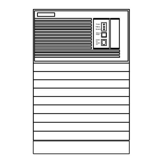
Page 25: Figure 1-1 Rack-Mounted Powertrust 5.5 Kva Ups
Overview Introduction Figure 1-1 Rack-mounted PowerTrust 5.5 kVA UPS This UPS provides 5.5 kVA of power protection for approximately 15 minutes. Chapter 1... -
Page 26: About This Book
Chapter 3: Installing the UPS Chapter 4: Power-On/Power-Off Procedures Chapter 5: Verification Procedures Chapter 6: Troubleshooting Chapter 7: Cleaning and Maintenance Appendix A: HP-UX UPS Monitor Error Messages Appendix B: MPE/iX UPS Monitor Error Messages Appendix C: Configuring the OS for the... -
Page 27: Terms Used In This Manual
Overview Terms Used in this Manual Terms Used in this Manual This section contains definitions of words and phrases that are used throughout this manual. automatic bypass Internal circuitry that detects a failure in the UPS's internal AC power path and bypasses the faulty circuitry so that AC input continues to supply power to the connected equipment. - Page 28 Overview Terms Used in this Manual rear panel The rear panel of the Electronics Unit and Service Bypass Unit. See Figure 1-3. The term "rear panel" never refers to the back of the Battery Box. Service Bypass Unit A unit located behind the Electronics Unit that can, when set properly, isolate the AC input source from the Electronics Unit and the batteries so that those components can be serviced without disrupting power to the load.
-
Page 29: Power Failure Operation
Overview Power Failure Operation Power Failure Operation When utility power fails, the UPS supplies internally generated AC voltage from its batteries for approximately fifteen (15) minutes at full load. As soon as the UPS detects a utility power failure, it generates an audible alarm. The alarm will sound approximately once every 10 seconds. -
Page 30: Electronics Unit And Bypass Operations
Timed Power-Off/Power-On PowerTrust UPS units installed on HP-UX systems also support a timed power-off/power-on facility. This allows you to power down the HP-UX system and have the PowerTrust UPS restore power to the system at a predetermined time. See the power_onoff(1M) man page for more information. -
Page 31: Control Panel Switches And Indicators
Overview Control Panel Switches and Indicators Control Panel Switches and Indicators The PowerTrust Electronics Unit has a user-accessible control panel on its front, as shown in Figure 1-2. Descriptions of the switches and indicators on the control panel follow the illustration. -
Page 32: Rear Panel Connectors, Switches, And Indicators (North American Version)
Overview Control Panel Switches and Indicators AC Output A green light indicates that AC power is being supplied to the output receptacles. Battery Power A yellow light indicates that the unit is supplying power from its batteries. Attention A yellow light indicates that the unit needs attention. This indicator (in conjunction with the audible alarm) has multiple meanings, as defined in Chapter 6, “Troubleshooting.”... - Page 33 Overview Control Panel Switches and Indicators Figure 1-3 Rear Panel Connectors, Switches, and Indicators (North American Version) AC Power Input A line cord with NEMA 6-50P plug attached. Used to connect the North American version of the UPS to an AC source or wall outlet. Figure 1-3 shows the AC power input for the 30A Service Bypass Unit.
- Page 34 If the wrong cable is used, the UPS will still function as stated in this manual, but the error messages and status logging described in Appendix A, “HP-UX UPS Monitor Error Messages.” and Appendix B, “MPE/iX UPS Monitor Error Messages.” will not be supported.
- Page 35 Overview Control Panel Switches and Indicators Battery The Battery Box is connected to the Electronics Unit using a battery Connector cable. The cable from the Battery Box is plugged into a connector at the bottom of the Electronics Unit. For information on how to connect the Electronics Unit to the Battery Box, refer to “Connecting the Battery Box Cable to the Electronics Unit”...
- Page 36 Overview Control Panel Switches and Indicators Bypass Switch This red button must be pressed to change the Service Bypass switch Activation Button setting from . (The button does not have to be pressed NORMAL BYPASS to change the setting from .) Pressing this button will BYPASS NORMAL...
- Page 37 Overview Control Panel Switches and Indicators UPS/BATTERY This slide switch enables or disables operation of the UPS. In the Switch position (switch to the right), the UPS functions normally. ENABLE Depending on other conditions, there may be voltage present at the AC output, and the UPS may be charging or discharging its batteries.
-
Page 38: Rear Panel Connectors, Switches, And Indicators (Worldwide Version)
Overview Control Panel Switches and Indicators Rear Panel Connectors, Switches, and Indicators (Worldwide Version) Figure 1-4 Rear Panel Connectors, Switches, and Indicators (Worldwide Version) Connectors and switches on the worldwide version are shown in Figure 1-4 and described below. Hardwired Output For the worldwide version, a hole with a strain relief is provided in the right access panel for making a hardwired output connection in a manner appropriate to local electrical codes. - Page 39 If the wrong cable is used, the UPS will still function as stated in this manual, but the error messages and status logging described in Appendix A, “HP-UX UPS Monitor Error Messages.” and Appendix B, “MPE/iX UPS Monitor Error Messages.” will not be supported.
- Page 40 Overview Control Panel Switches and Indicators Battery Connector The Battery Box is connected to the Electronics Unit using a battery cable. The cable from the Battery Box is plugged into a connector at the bottom of the Electronics Unit. For information on how to connect the Electronics Unit to the Battery Box, refer to “Connecting the Battery Box Cable to the Electronics Unit”...
- Page 41 Overview Control Panel Switches and Indicators Bypass Switch This red button must be pressed to change the Service Bypass Activation Button switch setting from . (The button does not have to NORMAL BYPASS be pressed to change the setting from .) Pressing BYPASS NORMAL...
- Page 42 Overview Control Panel Switches and Indicators UPS/BATTERY Switch This slide switch enables or disables operation of the UPS. In the position (switch to the right), the UPS functions normally. ENABLE Depending on other conditions, there may be voltage present at the AC output, and the UPS may be charging or discharging its batteries.
-
Page 43: Battery Box
Overview Battery Box Battery Box Each UPS includes a Battery Box that contains ten replaceable battery packs. Figure 1-5 PowerTrust UPS Battery Box Chapter 1 1-21... -
Page 44: Service Bypass Unit
Overview Service Bypass Unit Service Bypass Unit The Service Bypass Unit provides AC power distribution to and from the UPS. Figure 1-6 and Figure 1-7 shows the North American and Worldwide versions of the Service Bypass Unit, respectively. Figure 1-6 shows the 30A Service Bypass Unit. The 40A Service Bypass Unit has some differences. - Page 45 Overview Service Bypass Unit Figure 1-7 PowerTrust UPS Service Bypass Unit (30A) (Worldwide Version) Chapter 1 1-23...
-
Page 46: Specifications
Overview Specifications Specifications This section contains the specifications for the 5.5 kVA PowerTrust UPS, Model A3589A. Table 1-2 A3589A Specifications Description Specification Electrical Specifications AC Line Input: Rated Voltage 200-240 VAC @ 50/60 Hz Rated Current 50 ±3 Hz or 60 ± Hz Normal Operating Frequency Range Normal Operating Voltage Range 180-256 VAC... - Page 47 Overview Specifications Description Specification Overfrequency to Normal: For 50 Hz operation below 53.0 Hz For 60 Hz operation below 63.0 Hz AC Output: Output Voltage (and tolerance): On-line 230 VAC (+6%/-13%) On-battery 230 VAC (±3%) Auto or Service Bypass Same as the AC line input Output Frequency (and tolerance): On line Tracks input frequency...
- Page 48 Overview Specifications Description Specification Overload Protection: On-line or On-battery: Firmware protection: For >110% load Shuts down after a delay Input Breaker protection: Main UPS circuit breaker (50A) Auto or Service Bypass: Bypass circuit breaker (40A) Output Overload Protection: At Output #1 Output circuit breaker #1 (16A) At Output #2 Output circuit breaker #2 (16A)
- Page 49 Overview Specifications Description Specification Acoustic Noise: 7.5 Bels A-weighted sound power from any surface Physical Specifications - Electronics Unit Dimensions packaged Height - 43.82cm (17.25in) Width - 59.69cm (23.50in) Length - 95.25cm (37.50in) Weight - 77.73kg (171.0 lbs) Dimensions unpackaged Height - 34.4cm (13.54in) - 8 EIA units Width - 48.16cm (18.96in) Length - 80.74cm (30.79in) Weight - 68.19kg (150.0 lbs)
-
Page 50: Voltage And Frequency
Overview Specifications Description Specification Minimum Required Service Access Service access space Rear - 76.0cm (30.0in) Side - 0.0cm (0.0in) Front - 91.0cm (36.0in) Communication Specifications RS-232 port pinouts pin 1: Receive Data pin 2: Transmit Data pins 3-8: Reserved (Do not use) pin 9: Signal Ground Communication protocol 8 data bits, 1 stop bit, no parity, 1200 baud 1. - Page 51 Overview Specifications When the UPS becomes operational, it directs AC line voltage to the output connectors until the AC input falls out of range. When the AC input is out of range, the UPS internally generates regulated AC power for up to 15 minutes at rated load and sends it to the connected equipment through the output connectors.
-
Page 52: Figure 1-8 Ups Input Voltage Transfer Points
Overview Specifications Figure 1-8 UPS Input Voltage Transfer Points 1-30 Chapter 1... -
Page 53: Frequency
Overview Specifications Figure 1-9 UPS Frequency Transfer Points Frequency The UPS is designed to operate from nominal 50 Hz or 60 Hz power systems. Selection between 50 Hz and 60 Hz operation is performed automatically by the UPS at initial power on. -
Page 54: Ups Modes
Overview UPS Modes UPS Modes The UPS has four modes of operation: On-line, On-battery, Automatic Bypass, and Service Bypass. On-line Mode When the UPS is operating normally, it is in On-line mode. In this mode, it is monitoring the AC input line and providing AC power to the output receptacles. AC input power enters the Electronics Unit through the MAIN circuit breaker in the Service Bypass Unit (SBU). -
Page 55: Service Bypass Mode
Overview UPS Modes Service Bypass Mode This mode allows the Electronics Unit, Battery Box, Control Panel, and Fan to be serviced while still providing AC input power to the connected equipment. In contrast to Automatic Bypass mode, which is triggered on automatically by the UPS, Service Bypass mode occurs when the Service Bypass switch is manually turned to BYPASS. - Page 56 Overview UPS Modes Figure 1-10 Simplified UPS 5.5 kVA UPS Block Diagram 1-34 Chapter 1...
-
Page 57: Sleep Mode
UPS uses a minimum of battery power. Sleep Mode is normally initiated by the operating system (HP-UX) sending a shutdown ("S") command to the UPS to conserve Battery power. (This is the case when AC input fails, or its magnitude, frequency or waveshape are out-of-spec, for a prolonged period of time). -
Page 58: Ups Safety Preparedness
UPS products. UPS products must go through rigorous testing to ensure their safety, the same as all of HP's computer-related products. UPS products are proven to be safe under normal and most abnormal conditions. However, failed or stressed components within the UPS may present safety hazards in the form of: •... -
Page 59: Hazardous Product Information
Where to find help: • Refer to your site's emergency response procedures. • Refer to the handbook, Electrical Safety &Lockout/Tagout. • Call the HP Response Center, if you are uncertain about how to proceed. Hazardous Product Information Hazardous Components: Percent:... - Page 60 Overview UPS Safety Preparedness Situation: Procedure: Handling released or spilled If a battery is accidentally broken and electrolyte material: (sulfuric acid) leaks out, put on waterproof gloves and wipe it up with a cloth. Neutralize the acid with some alkaline substance such as ammonia solution or baking soda (sodium bicarbonate).
-
Page 61: Support Information
Two CEs are required to install or replace the heavy electronics assemblies. Training UPS training is self-paced with optional lab exercises — CE42-PWRTRUST55, HP P/N A3589-60101. Battery Type The battery type is rechargeable, maintenance free, and sealed lead-acid. - Page 62 Overview Support Information 1-40 Chapter 1...
-
Page 63: Unpacking And Inspecting
Unpacking and Inspecting Unpacking and Inspecting This chapter describes: • Receiving the PowerTrust UPS • Unpacking the UPS • Claims procedures • Shipping and storage requirements The following procedures, as well as all other service, cleaning, and WARNING maintenance of the UPS, should be performed only by qualified service-trained Hewlett-Packard personnel. -
Page 64: Receiving The Powertrust Ups
Unpacking and Inspecting Receiving the PowerTrust UPS Receiving the PowerTrust UPS First, check that the order is complete as specified in the carrier's Bill of Lading. Sometimes several orders are combined into one shipment. Inspect each container for evidence of mishandling during transit. Request that the carrier's agent be present when any damaged containers are opened. -
Page 65: Unpacking The Ups
Unpacking and Inspecting Unpacking the UPS Unpacking the UPS Each PowerTrust Electronics Unit, Battery Box, and Service Bypass Unit is shipped in a separate carton; the cartons are stacked and banded together on a shipping pallet. The bottom carton contains the Electronics Unit, the middle carton contains the Battery Box, and the top carton contains the Service Bypass Unit. -
Page 66: Cutting The Shipping Straps
Unpacking and Inspecting Unpacking the UPS To unpack the PowerTrust UPS, you must cut the straps that secure the UPS to the pallet and unpack the shipping containers from the top down. The following subsections contain step-by-step procedures for unpacking the UPS. Cutting the Shipping Straps The straps that secure the cartons to the pallet are under tension. -
Page 67: Figure 2-2Unpacking The Powertrust Service Bypass Unit
Unpacking and Inspecting Unpacking the UPS Figure 2-2Unpacking the PowerTrust Service Bypass Unit 3. Remove any additional material, such as manuals or cords, from the top of the unit and set them aside. 4. Remove the packing material on which the power cord was resting. 5. -
Page 68: Unpacking The Battery Box
Unpacking and Inspecting Unpacking the UPS Unpacking the Battery Box Figure 2-3 Unpacking the PowerTrust Battery Box To unpack the Battery Box and battery packs: 1. While the carton containing the Battery Box is still on the shipping pallet, open it. 2. -
Page 69: Removing Battery Packs From Battery Box
Unpacking and Inspecting Unpacking the UPS With the batteries installed, each Battery Box weighs about 180 kg WARNING (396 lbs.) Do not attempt to lift the Battery Box out of the shipping carton. Use the procedure in “Removing Battery Packs from Battery Box”. -
Page 70: Figure 2-5 Removing A Battery Pack From The Battery Box
Unpacking and Inspecting Unpacking the UPS 3. Position your free hand under the battery pack for support. See Figure 2-5. 4. Carefully pull the battery pack all the way out of the slot and set it aside in a safe place. Each battery pack weighs approximately 14.5 kg (33 lbs). -
Page 71: Unpacking The Electronics Unit
Unpacking and Inspecting Unpacking the UPS Figure 2-6 Unpacking the PowerTrust Electronics Unit Unpacking the Electronics Unit WARNING The Electronics Unit weighs about 68 kg (150 lbs.) unpacked. At least two people are required to lift it. Refer to Figure 2-6 while removing the Electronics Unit from its shipping carton: 1. - Page 72 Unpacking and Inspecting Unpacking the UPS 6. Check the packing material for signs of damage, which could indicate rough handling during transit. Also look for damage such as broken controls and connectors, dented corners, scratches, bent panels, and loose components. Refer to “Claims Procedures” later in this chapter if you discover any damage.
-
Page 73: Claims Procedures
Unpacking and Inspecting Claims Procedures Claims Procedures If the PowerTrust UPS is damaged, follow the procedures outlined in this section. Notify the nearest Hewlett-Packard Sales and Service Office if the shipment is incomplete, damaged, or fails to meet specifications. If damage occurred in transit, also notify the carrier. -
Page 74: Shipping And Storage Requirements
Unpacking and Inspecting Shipping and Storage Requirements Shipping and Storage Requirements The PowerTrust UPS can be shipped or stored under the following (non-operating) conditions and environmental limits: • The UPS/BATTERY switch must be in the position. DISABLE • Temperature limits: •... -
Page 75: Figure 2-8 Battery Pack Shelf-Life Storage Time Vs Temperature
Unpacking and Inspecting Shipping and Storage Requirements Figure 2-8 Battery Pack Shelf-Life Storage Time vs Temperature • Recommended temperature: 20° to 25°C • Humidity: 5% to 90% non-condensing at 65°C • Altitude: 4,572 meters (15,000 feet) • The batteries must be recharged periodically depending on the storage temperature. Storing battery packs without recharging periodically will cause damage to CAUTION the battery packs, resulting in reduced run time. - Page 76 Unpacking and Inspecting Shipping and Storage Requirements 2-14 Chapter 2...
-
Page 77: Installing The Ups
Installing the UPS Installing the UPS This chapter contains information about: • Sizing the load • Rackmounting procedures • Hardwired connections • Cabling connections • Examples of PowerTrust connections in a system WARNING The following procedures, as well as all other service, cleaning, and maintenance of the UPS, should be performed only by qualified service-trained Hewlett-Packard personnel. -
Page 78: Sizing The Load
In most cases, equipment is rated high so that the sum of the values for all of the equipment is equal to or less than the actual load. Note that power load values listed for HP devices in the HP3000 and HP9000 Configuration Guides are not "worst case"; they represent realistic loading values. -
Page 79: Rackmounting Procedures
Installing the UPS Rackmounting Procedures Rackmounting Procedures The PowerTrust UPS is designed to be installed at the bottom of the Hewlett-Packard A1883A, A1884A, A1896A, or A1897A expansion cabinet (19-inch rack). Before you begin, check that the following switch settings have been made: 1. -
Page 80: Figure 3-1 Rail Locations For The Battery Box
Installing the UPS Rackmounting Procedures 2. Install two rails at the bottom-most position in the expansion cabinet. Four clip-nuts are needed and should be placed in the 3rd hole up from the bottom on each cabinet side frame rail. (Refer to Figure 3-1.) Do not install rail stops. -
Page 81: Figure 3-2 Battery Box Corner Mounting Locations
Installing the UPS Rackmounting Procedures Figure 3-2 Battery Box Corner Mounting Locations 6. Install all ten battery packs into the Battery Box. Install the battery packs one at a time, moving from left to right. a. Slip the guide at the bottom of the new battery pack between the tracks at the bottom of the Battery Box and push the battery completely into the Battery Box slot. -
Page 82: Installing The Electronics Unit In The Rack
Installing the UPS Rackmounting Procedures Figure 3-3 Inserting a Battery Pack into the Battery Box Installing the Electronics Unit in the Rack 1. Install two rails just above the Battery Box. Four clip-nuts are needed and should be placed in the 24th hole up from the bottom of each cabinet side frame rail. 2. -
Page 83: Figure 3-4 Rail And Clip-Nut Locations For Rackmounting The Electronics Unit
Installing the UPS Rackmounting Procedures Figure 3-4 Rail and Clip-Nut Locations for Rackmounting the Electronics Unit 3. With the help of one other person, grasp the strap handles, lift the Electronics Unit, and slide it into the rackmount position from the front of the expansion cabinet, just above the Battery Box. -
Page 84: Installing The Service Bypass Unit
Installing the UPS Rackmounting Procedures Installing the Service Bypass Unit 1. At the rear of the cabinet, place four clip-nuts (two per side) onto holes at the following positions: a. Two clip-nuts (one per side) at the 32nd hole up from the bottom of the cabinet frame rail. -
Page 85: Attaching Front Bezel
Installing the UPS Rackmounting Procedures 3. Slide the Service Bypass Unit onto the shelf of the Electronics Unit until the connector at the back of the Electronics Unit is aligned with the connector on the Service Bypass Unit. 4. Carefully push the Service Bypass Unit into the cabinet until the connector is fully engaged. -
Page 86: Power Distribution Unit (Pdu)
Installing the UPS Rackmounting Procedures Figure 3-6 Attaching the Front Bezel to the Electronics Unit Power Distribution Unit (PDU) Both the factory-integrated and field-integrated versions of the PowerTrust UPS require the use of a UPS-compatible Power Distribution Unit (PDU or "power strip") on the expansion cabinet containing the device(s) to be protected by the UPS. -
Page 87: Connecting The Battery Box Cable To The Electronics Unit
Installing the UPS Rackmounting Procedures 5. Insert and tighten two screws at each bracket to secure both PDUs to each bracket. 6. Attach a ground wire from the new PDU to the chassis (see Figure 3-7). This ground wire is required for safe operation of the unit. Figure 3-7 PDU Ground Connection Connecting the Battery Box Cable to the Electronics Unit Use the following procedure to connect the cable from the Battery Box to the Electronics... -
Page 88: Figure 3-8 Battery Precharge Shorting Plate
Installing the UPS Rackmounting Procedures Figure 3-8 Battery Precharge Shorting Plate 3. Use a screwdriver to loosen the screw at the center of each thumbscrew, then unscrew the thumbscrews on either side of the plate and remove it. 4. From the Battery Box, remove the plastic cover marked "REMOVE FOR ASSEMBLY" and dispose of it. -
Page 89: Figure 3-9 Reattaching Battery Precharge Shorting Plate
Installing the UPS Rackmounting Procedures If the Precharge Failure LED is blinking, do not reinstall the Battery WARNING Precharge Shorting Plate. Severe product damage can result. Refer to “Case 14 (Abnormal) — Battery Precharge Failure” in Chapter 6. 8. Orient the plate so that the notch on the plate is positioned over the Battery Box cable connector, then reattach the plate making sure that the prongs on the plate are pressed firmly into the clips in the Electronics Unit. -
Page 90: Input And Output Connections
Installing the UPS Input and Output Connections Input and Output Connections WARNING Only a qualified electrician should make the hardwired connections. NOTE 5.5 kVA, 30A PowerTrust UPS products that are sold in Europe are shipped without a line cord. It is the responsibility of the customer to get the correct power cord for the particular country and electrical code, and to have the power cord wired to the UPS input terminals. -
Page 91: Torque Specifications
Installing the UPS Input and Output Connections Output wiring should be sized based on input current requirements of the load equipment, in accordance with local codes. Figure 3-10 A3589A Terminal Block Torque Specifications Use a flat-bladed screwdriver to secure the screws to the terminal block. The following torque specifications are required: For Line and Ground Terminals: 10.6 - 12.3 in-lb (1.2 - 1.4 Nm) Removing the Access Panels... -
Page 92: Worldwide Version Input Wiring
Installing the UPS Input and Output Connections Worldwide Version Input Wiring For 200-240V, 50 or 60Hz: • Line (or Line 1): Connect wire to the L1 IN terminal. • Neutral (or Line 2) Connect wire to the L2/N IN terminal. •... -
Page 93: Cabling Connections
Installing the UPS Cabling Connections Cabling Connections Connecting Equipment to the PowerTrust UPS (with 30A Service Bypass Unit Only) This section describes how to connect equipment to a UPS with a 30A Service Bypass Unit. For information on how to connect equipment to a UPS with a 40A Service Bypass Unit, refer to Appendix E, “40A Service Bypass Unit: Specifications and Procedures.”... - Page 94 2. Attach the other end of the RS-232 cable to the appropriate RS-232 connector on the computer equipment as listed: • For HP 3000 computers, the RS-232 connection is made at a 25-pin modem-type port on a DTC that is configured to the computer.
-
Page 95: Examples Of Powertrust Connections In A System
Installing the UPS Examples of PowerTrust Connections in a System Examples of PowerTrust Connections in a System The following figures show examples of how to connect the PowerTrust UPS with a 30A Service Bypass Unit in an expansion cabinet. For examples of how to connect a UPS with a 40A Service Bypass Unit, refer to Appendix E, “40A Service Bypass Unit: Specifications and Procedures.”... -
Page 96: Example 1: Single Expansion Cabinet System (Field-Integrated)
Installing the UPS Examples of PowerTrust Connections in a System Example 1: Single Expansion Cabinet System (Field-Integrated) Figure 3-11 shows a field-integrated system with one expansion cabinet. Note these features: • A second (switchless) PDU (identified as the UPS PDU) has been installed. This PDU receives its power from the IEC320 C19 connector on the PowerTrust UPS. -
Page 97: Figure 3-11 Example 1: 99X/T-Class Spu With One Field-Integrated Expansion Cabinet
Installing the UPS Examples of PowerTrust Connections in a System Figure 3-11 Example 1: 99x/T-Class SPU with One Field-Integrated Expansion Cabinet Chapter 3 3-21... -
Page 98: Example 2: Single Expansion Cabinet System (Factory-Integrated)
Installing the UPS Examples of PowerTrust Connections in a System Example 2: Single Expansion Cabinet System (Factory-Integrated) Figure 3-12 shows a factory-integrated system with one expansion cabinet. Note these features: • One switchless Power Distribution Unit (PDU) is installed. This PDU receives its power from the IEC320 C19 connector on the PowerTrust UPS. -
Page 99: Figure 3-12 Example 2: 99X/T-Class Spu With One Factory-Integrated Expansion Cabinet
Installing the UPS Examples of PowerTrust Connections in a System Figure 3-12 Example 2: 99x/T-Class SPU with One Factory-Integrated Expansion Cabinet Chapter 3 3-23... -
Page 100: Example 3: Dual Expansion Cabinet System (Field-Integrated)
Installing the UPS Examples of PowerTrust Connections in a System Example 3: Dual Expansion Cabinet System (Field-Integrated) Figure 3-13 shows a field-integrated system with two expansion cabinets. Note these features: • A second (switchless) PDU (identified as the UPS PDU) has been installed in each expansion cabinet. -
Page 101: Figure 3-13 Example 3: 99X/T-Class Spu Two Field-Integrated Expansion Cabinets
Installing the UPS Examples of PowerTrust Connections in a System Figure 3-13 Example 3: 99x/T-Class SPU Two Field-Integrated Expansion Cabinets Chapter 3 3-25... -
Page 102: Example 4: Dual Expansion Cabinet System (Factory-Integrated)
Installing the UPS Examples of PowerTrust Connections in a System Example 4: Dual Expansion Cabinet System (Factory-Integrated) Figure 3-14 shows a factory-integrated system with two expansion cabinets. Note these features: • Only one PDU is installed in each expansion cabinet. Both PDUs receive their power from the PowerTrust UPS located in the right-hand expansion cabinet. -
Page 103: Figure 3-14 Example 4: 99X/T-Class Spu With Two Factory-Integrated Expansion Cabinets
Installing the UPS Examples of PowerTrust Connections in a System Figure 3-14 Example 4: 99x/T-Class SPU with Two Factory-Integrated Expansion Cabinets Chapter 3 3-27... - Page 104 Installing the UPS Examples of PowerTrust Connections in a System 3-28 Chapter 3...
-
Page 105: Power-On/Power-Off Procedures
Power-On/Power-Off Procedures Power-On/Power-Off Procedures This chapter contains the procedures for: • Initial power-on • Powering-on and powering-off during normal operation • Switching into and out of Service Bypass mode • Powering-off for an extended time This chapter also discusses the Emergency Power Off (EPO) connection, and battery charging. -
Page 106: Power-On Procedures
Power-On/Power-Off Procedures Power-On Procedures Power-On Procedures Initial Power-On or Power-On After Shutdown Use the following procedure to power-on the UPS for the first time after it is installed or after the UPS has been shutdown for an extended of time (see “Powering-Off the UPS for an Extended Time”). - Page 107 Power-On/Power-Off Procedures Power-On Procedures • AC Output LED: on • Battery LED: off • Attention LED: off • Audible Alarm: none • Enable LED: on • Caution LED: off If any of indicators differ from the above, the UPS did not power up correctly. Refer to Chapter 6, “Troubleshooting.”...
-
Page 108: Power-Off Procedures
Power-On/Power-Off Procedures Power-Off Procedures Power-Off Procedures Powering-Off the UPS for an Extended Time You should follow the procedure for powering off the UPS for an extended time when: • A power failure has occurred or input AC power will be off for an extended time (more than 24 hours). -
Page 109: Service Bypass
Power-On/Power-Off Procedures Service Bypass Service Bypass Service Bypass mode allows the Electronics Unit and Battery Box to be serviced without disrupting AC output. CAUTION Do not push the red button while the UPS is operating on battery. Damage to the connected equipment can occur. Placing the UPS in Service Bypass Mode The UPS should be placed in Service Bypass mode only by qualified service personnel or under their direction. -
Page 110: Taking The Ups Out Of Service Bypass Mode
Power-On/Power-Off Procedures Service Bypass • Battery LED: off • Attention LED: on • Audible Alarm: solid tone (The alarm may be silenced by pressing the Silence Alarm/Test switch.) If the Caution LED is flashing, STOP! You may interrupt AC input to the CAUTION connected equipment if you attempt to place the UPS in Service Bypass mode. -
Page 111: Emergency Power Off (Epo) Connections
Power-On/Power-Off Procedures Emergency Power Off (EPO) Connections Emergency Power Off (EPO) Connections A pair of terminals is provided for connection to an EPO system. For normal operation, the terminals must be connected by a jumper or connected to a normally closed EPO switch. If the terminals are not connected together, or the EPO switch has been activated (opened), the UPS will shutdown AC output power to the output receptacles in On-line mode, On-battery mode, or Automatic Bypass mode. -
Page 112: Charging The Batteries
Power-On/Power-Off Procedures Charging the Batteries Charging the Batteries The 5.5 kVA PowerTrust UPS's batteries must be charged before the UPS can provide battery generated output AC power in the event of an input power failure. For the batteries to charge, input AC power must be present, the UPS/BATTERY switch must be in the position, and the MAIN INPUT breaker must be ON. -
Page 113: Verification Procedures
Verification Procedures Verification Procedures This chapter contains information on how to verify that the UPS is installed correctly after initial installation or service, and that it is not overloaded. WARNING The following procedures should be performed only by qualified service-trained Hewlett-Packard personnel. Chapter 5... -
Page 114: Load Testing
Verification Procedures Load Testing Load Testing Load testing is required to verify that the PowerTrust UPS is correctly installed, and that the equipment attached to the PowerTrust UPS does not put the unit in an overload condition. Except when it is in Bypass mode (Service or Automatic), the UPS continuously monitors load current, automatically, without operator intervention. - Page 115 Verification Procedures Load Testing 3. Take action based on one of these conditions: a. If the indications in step 2 occur, the equipment attached to the UPS is within the accepted load range of the UPS. Proceed to step 4. b.
- Page 116 Verification Procedures Load Testing Chapter 5...
-
Page 117: Chapter 6: Troubleshooting
Troubleshooting Troubleshooting This chapter provides some information to assist you in troubleshooting the UPS. Using it will help you determine the urgency of the condition and possible actions to take. These are the topics in this chapter. • Troubleshooting aids •... -
Page 118: Troubleshooting Troubleshooting Aids
Chapter C, “Configuring the OS for the PowerTrust UPS.”. Without Operating System Assistance If your computer system is an MPE/iX system or a version of HP-UX earlier than 9.04, then it cannot provide assistance in a power fail situation. During an AC power failure, operator intervention is required to shut down the protected equipment and the UPS before the battery power is depleted. -
Page 119: Rs-232 Ups Port Does Not Respond
The following are possible causes for the RS-232 port not responding on an MPE/iX or HP-UX system: • The version of the operating system is required to support UPS is not valid: HP-UX 9.04 (or later) or MPE/iX 5.0 (or later). -
Page 120: Checking The Voltage Of A Battery Box Or A Battery Pack
Troubleshooting Checking the Voltage of a Battery Box or a Battery Pack Checking the Voltage of a Battery Box or a Battery Pack WARNING The following procedure should be performed by qualified service personnel only. The battery packs in the Battery Box are connected in series-parallel; that is, the five packs at the front and the five packs at the back are in parallel, and each of the two groups of five battery packs is connected in series with the other group of five. -
Page 121: Overtemperature Considerations
Troubleshooting Overtemperature Considerations Overtemperature Considerations Overtemperature sensing is done inside the Electronics Unit for the protection of the internal components of the UPS. Refer to the temperature specifications for your system in Table 1-2. Overtemperature can occur under a variety of conditions, but is most often the result of rising ambient temperatures, blocked airflow of the cooling fan, or blocked outlet holes. -
Page 122: Alarm Indicators
Troubleshooting Alarm Indicators Alarm Indicators Interpreting indicators and audible alarms and suggested actions are included in the case descriptions. Figure 6-1 shows the possible indicator light combinations and relates each to a case number. Front Panel Visible Indicators (LEDs) The following three indicator lights (LEDs) are located on the front control panel of the Electronics Unit as shown in Figure 1-2. -
Page 123: Precharge Failure Led
Troubleshooting Alarm Indicators Caution LED is flashing, changing the position of the Service Bypass switch may interrupt AC output to the load. Therefore, do not change the position of the Service Bypass switch when the Caution LED is blinking unless there is no load or the load is not running. The following table lists the possible reasons for caution LED to be blinking. -
Page 124: Silence Alarm/Test
Troubleshooting Alarm Indicators Continuous tone alarm A continuous tone indicates that the UPS has switched to Automatic Bypass mode. Silence Alarm/Test The Silence Alarm/Test switch is a push-button switch on the front panel. Pressing this switch silences the alarm if the audible alarm is active. This only cancels the audible alarm, it does not correct the condition that caused the alarm. -
Page 125: Figure 6-1 Alarm Indications
Troubleshooting Alarm Indicators Case Symptom Page # Battery Precharge Failure 6-19 UPS Off or Asleep 6-20 Bypass Sleep Mode 6-22 Figure 6-1 Alarm Indications Chapter 6... -
Page 126: Normal Led And Alarm Condition
Troubleshooting Normal LED and Alarm Condition Normal LED and Alarm Condition Case 1 (Normal) — UPS Running on AC Power The unit is functioning normally. Indicators: AC Output not lit Battery Power not lit Attention Caution LED not lit Enable lit Audible alarm: none Meaning: The output to the protected equipment is enabled and the UPS is... -
Page 127: Ups Running On Ac Power With Audible Alarm
1. Make sure the BYPASS and MAIN INPUT circuit breakers are ON. CAUTION If the yellow caution light is flashing, do not proceed. Call HP Service. If the yellow caution light is not flashing, continue. 2. While depressing the red button on the Service Bypass Unit, set the... -
Page 128: Case 4 (Normal Or Abnormal) - Bypass Mode
2. Check if there is a problem with the environment, and if so, take actions to correct the problem. 3. If the problem is with the unit, power-off the UPS, and call HP Service. See “Power-Off Procedures” in Chapter 4. -
Page 129: Case 5 (Normal) - Overload Warning On-Line
Troubleshooting UPS Running on AC Power with Audible Alarm • The UPS has been placed in Service Bypass (see “Service Bypass” in Chapter 4). Abnormal causes of this case are: • The UPS microprocessor detected a UPS internal failure and placed the unit in Automatic Bypass mode. - Page 130 2. Move the input connections of the equipment that was powered-off in step 1 to another power source. NOTE For information on adjusting the load size, refer to “Sizing the Load”. Call HP Service if you need assistance in resizing the load. 6-14...
-
Page 131: Ups Running On Battery Power With Audible Alarm
When AC power returns, power on the protected equipment. • For systems with automatic shutdown procedure: a. No action is required. The HP-UX system will power-down the UPS automatically. b. The system will power-up automatically when AC power returns. -
Page 132: Case 7 (Normal) - Low Battery
2. When AC power returns, power on the protected equipment. • For systems with automatic shutdown procedure: 1. No action is required. The HP-UX system will power-down the UPS automatically. 2. The system will power-up automatically when AC power returns. -
Page 133: Case 8 (Normal) - Overload Warning On Battery
1 to another power source. For information on adjusting the load size, refer to “Sizing the Load” in NOTE Chapter 3 and “Load Testing” in Chapter 5. Call HP Service if you need assistance in resizing the load. CAUTION Do not push the red Bypass Switch Activation button while the UPS is operating on Battery. -
Page 134: Ups Halted (Has No Ac Output)
2. At this point, it may be possible to restore the operation of the equipment powered by the UPS (but without UPS power fail protection) by placing the UPS in Service Bypass mode until an HP Service person arrives. (See “Placing the UPS in Service Bypass Mode” in Chapter 4.) Case 10 (Normal or Abnormal) —... - Page 135 Troubleshooting UPS Halted (Has No AC Output) • There is an excessive UPS load or a short-circuit at the UPS output. Abnormal causes of this case are: • Internal EPO circuits of the UPS are defective. • An internal short-circuit or failed component may exist at the output circuits of the UPS.
-
Page 136: Case 11 (Normal, Abnormal) - Overtemperature Shutdown
• Power-down the UPS. • Put the UPS in Bypass mode by switching the Service Bypass switch BYPASS • Call HP Service and report on the status of the fan when the UPS shut down. Case 12 (Normal or Abnormal) — Output Disabled... - Page 137 Troubleshooting UPS Halted (Has No AC Output) • The UPS output has been turned off with the Output On/Output Off switch. For this cause, use Action 1 below to recover. • The UPS output has been turned off by a command from the host computer system and has not been commanded to turn back on.
-
Page 138: Case 14 (Abnormal) - Battery Precharge Failure
2. A faulty battery cable. Actions: 1. Make sure the BYPASS and MAIN INPUT circuit breakers are ON. If the yellow caution light is flashing, do not proceed. Call HP Service. If the CAUTION yellow caution light is not flashing, continue. -
Page 139: Case 15 (Normal Or Abnormal) - Ups Off Or Asleep
• Prolonged period during which the AC input frequency is not within spec. • For UPSs attached to a HP-UX host system, the system commanded the UPS to go to sleep some time after it was informed by the UPS that it had to go to battery operation (after detecting one of the causes above). -
Page 140: Case 16 (Normal Or Abnormal) - Bypass Sleep Mode
Troubleshooting UPS Halted (Has No AC Output) • The Battery Precharge Shorting Plate is not properly installed onto the corresponding connector blades of the Electronics Unit. • Deeply discharged (or dead) UPS batteries. • Internal failure at the UPS input circuits or auxiliary power sources. •... - Page 141 Troubleshooting UPS Halted (Has No AC Output) Attention Caution LED not lit Enable not lit Audible Alarm: continuous Meaning: This case indicates that the UPS internal circuits have become dormant after 30 minutes of operation in Automatic or Service Bypass mode (see “Case 4 (Normal or Abnormal) —...
- Page 142 Troubleshooting UPS Halted (Has No AC Output) If the UPS returns to normal operation, that is, with the UPS running on AC power, then it is either OK and must have entered Automatic Bypass because the Bypass Switch Activation button was pressed, or the UPS has an intermittent fault that occasionally puts it in Automatic Bypass and then clears itself.
-
Page 143: Cleaning And Maintenance
Cleaning and Maintenance Cleaning and Maintenance This chapter describes simple cleaning and maintenance procedures for the PowerTrust UPS. The PowerTrust UPS requires little or no maintenance. Occasionally, the input and output connections should be inspected for signs of damage. WARNING The following procedures should be performed only by qualified service-trained Hewlett-Packard personnel. -
Page 144: Cleaning
Cleaning and Maintenance Cleaning Cleaning 1. Shut down the operating system. 2. Set the front panel Output On/Output Off switch to Output Off 3. Set the INPUT circuit breakers (MAIN and BYPASS) to the OFF position. 4. Set the rear panel UPS/BATTERY switch to the position. -
Page 145: Recommended Periodic Testing
Cleaning and Maintenance Recommended Periodic Testing Recommended Periodic Testing Hewlett-Packard recommends periodic testing of the PowerTrust unit to determine if it is capable of providing the specified functionality. 1. Notify users of the computer system that power testing of the computer equipment will be performed. -
Page 146: Exchanging Batteries/Fan
Exchanging Batteries/Fan Exchanging Batteries/Fan WARNING Only qualified service-trained HP personnel should replace or service the batteries or fan. The unit comes equipped with sealed, maintenance free, lead-acid batteries. Battery lifetime is impossible to predict accurately because of the many variables of load, cycling, and ambient temperature involved. -
Page 147: Exchanging The Fan
↑↑↑↑ The first four digits (L97F) specify the UPS part and manufacturing date. The 1st digit specifies the UPS part. For a 24V HP battery pack this designation is always "L." The 2nd and 3rd digits specify the year the battery pack was manufactured. In the example, the year is 1997. - Page 148 Cleaning and Maintenance Exchanging Batteries/Fan Chapter 7...
-
Page 149: Hp-Ux Ups Monitor Error Messages
PowerTrust unit. The term UPS Monitor refers to the software utility (ups_mond) that monitors PowerTrust operation. The UPS Monitor daemon is not designed to used with any UPS other than an HP PowerTrust. All messages are indexed by their exact text. Look up the message text in the index to find the page where the definition occurs. -
Page 150: Introduction
Under some alarm conditions, it might not be able to. The message may be delayed until AC input power has been restored. In other cases, the message may be lost. If your computer system is HP-UX version 9.04 (or later), the operating system also provides automatic shut down of the equipment. -
Page 151: Normal Operation Messages
HP-UX UPS Monitor Error Messages Normal Operation Messages Normal Operation Messages The messages in this section may appear during normal operation. MESSAGE ups_mond: UPS Monitor daemon starting; using configuration file <filename> SEVERITY Information. Startup processing program message. MEANING UPS Monitor process creation and activation daemon has successfully begun execution. - Page 152 HP-UX UPS Monitor Error Messages Normal Operation Messages MESSAGE ups_mond: AC Power to all recognized, system critical UPSs OK! System will not shutdown. SEVERITY Information. A previous critical or warning condition related to AC input power has been corrected. MEANING...
-
Page 153: Timer Controlled Power On/Off Messages
HP-UX UPS Monitor Error Messages Timer Controlled Power On/Off Messages Timer Controlled Power On/Off Messages The following messages relate to the Timer Controlled Power On/Off utility. See power_onoff(1M) for more information about the utility. MESSAGE ups_mond: Timer Controlled On/Off information invalid;... - Page 154 HP-UX UPS Monitor Error Messages Timer Controlled Power On/Off Messages MESSAGE ups_mond: open error: <error number> for Timed On/Off fifo file /timed_off; continuing without SEVERITY Error. MEANING Could not open fifo (also known as a "pipe") for reading request from the power_onoff utility.
- Page 155 HP-UX UPS Monitor Error Messages Timer Controlled Power On/Off Messages MESSAGE ups_mond: Timer Controlled On value exceeds UPS <tty special file name> maximum. The maximum value of <value> will be used for this UPS. SEVERITY Warning. Turn-on date and time will be earlier than requested.
-
Page 156: Exit Ups_Mond Daemon Messages
HP-UX UPS Monitor Error Messages Exit ups_mond Daemon Messages Exit ups_mond Daemon Messages The messages in this section precede the exiting of the ups_mond daemon. After the appearance of one of these messages, the UPS Monitor will not be running, thus the affected PowerTrust unit(s) will not be monitored. - Page 157 HP-UX UPS Monitor Error Messages Exit ups_mond Daemon Messages MESSAGE ups_mond: permission denied; must be super user SEVERITY Error. MEANING Must be super user to execute ups_mond. CAUSE An attempt was made to start ups_mond without super user capability. ACTION ups_mond is designed to be started from /etc/inittab by init, which has super user capability.
- Page 158 HP-UX UPS Monitor Error Messages Exit ups_mond Daemon Messages MESSAGE ups_mond: aborted, configfile <filename> open received error: <error number> SEVERITY Error. MEANING Could not open the ups_mond configuration file. CAUSE The specific cause is denoted by the <error number> in the message.
- Page 159 HP-UX UPS Monitor Error Messages Exit ups_mond Daemon Messages MESSAGE ups_mond: terminated by signal <decimal value> SEVERITY Information. MEANING The signal received by ups_mond caused termination. CAUSE The signal denoted by <decimal value> in the message was received. The most common cause is a kill of the ups_mond process.
-
Page 160: Shutdown(1M) Messages
HP-UX UPS Monitor Error Messages shutdown(1M) Messages shutdown(1M) Messages The messages in this section may precede a shutdown(1M) attempt, depending on the particular PowerTrust configuration in the system. MESSAGE ups_mond: UPS <tty special file name> AC POWER FAILURE - running on UPS battery SEVERITY Warning. - Page 161 HP-UX UPS Monitor Error Messages shutdown(1M) Messages MESSAGE If power is not returned within previously configured time period, your system will automatically go to graceful shutdown. SEVERITY Warning. Critical (not MSG-ONLY) PowerTrust units have lost AC power. MEANING One or more critical PowerTrust units are supplying reserve power from their batteries.
-
Page 162: Reboot(2) Messages
HP-UX UPS Monitor Error Messages reboot(2) Messages reboot(2) Messages The messages in this section may precede a reboot(2), depending on the particular PowerTrust configuration in the system. NOTE All of the reboot(2) messages will be followed by: ups_mond: reboot -halt invoked due to UPS error cited in previous syslog message. - Page 163 HP-UX UPS Monitor Error Messages reboot(2) Messages MESSAGE ups_mond: UPS <tty special file name> no output - either switch setting wrong on UPS or bad UPS SEVERITY Critical. No power output from the PowerTrust device configured as <tty special file name>.
-
Page 164: Appendix A: Hp-Ux Ups Monitor Error Messages
HP-UX UPS Monitor Error Messages reboot(2) Messages MESSAGE ups_mond: UPS <tty special file name> failed - requires repair SEVERITY Critical. PowerTrust hardware has failed, and PowerTrust output power has been lost. Some system component(s) now without power. MEANING The PowerTrust device configured as <tty special file name> is faulty. If the specified PowerTrust unit is a critical PowerTrust unit, then the system will... - Page 165 HP-UX UPS Monitor Error Messages reboot(2) Messages MESSAGE ups_mond: UPS <tty special file name> ambient temperature too high; UPS turned itself off - reduce heat in area SEVERITY Critical. PowerTrust hardware has failed, and PowerTrust output power has been lost. Some system component(s) now without power.
- Page 166 HP-UX UPS Monitor Error Messages reboot(2) Messages MESSAGE ups_mond: UPS <tty special file name> output voltage too high; UPS turned itself off - requires repair SEVERITY Critical. PowerTrust hardware has failed, and PowerTrust output power has been lost. Some system component(s) now without power.
- Page 167 HP-UX UPS Monitor Error Messages reboot(2) Messages MESSAGE ups_mond: cannot reboot due to <error number> returned by exec(). SEVERITY Error. MEANING A reboot system call failed. CAUSE The specific cause is denoted by the <error number> in the message. ACTION Refer to exec(2) for more information on the error.
-
Page 168: Log-Only Messages
HP-UX UPS Monitor Error Messages Log-Only Messages Log-Only Messages The messages in this section are not displayed, but instead are logged in the syslog file. See the syslog(3C) man page for more information. MESSAGE ups_mond: warning - no upstty: UPS's found in configfile <filename>;... - Page 169 HP-UX UPS Monitor Error Messages Log-Only Messages MESSAGE ups_mond: UPS <tty special file name> interrupted, but read of ups status failed - possible UPS hardware problem SEVERITY Warning. MEANING The PowerTrust device configured as <tty special file name> experienced a state change, but no status information was communicated to the UPS Monitor.
- Page 170 HP-UX UPS Monitor Error Messages Log-Only Messages MESSAGE ups_mond: upstty <tty special file name> failed open: <error number>; ignoring that tty and continuing SEVERITY Warning/Error. System hardware powered by the specified PowerTrust unit is UNPROTECTED. MEANING The PowerTrust device configured as <tty special file name> could not establish communication with the UPS Monitor.
- Page 171 HP-UX UPS Monitor Error Messages Log-Only Messages MESSAGE ups_mond: UPS <tty special file name> ioctl(TCSETAF) failed: <error number>; ignoring that UPS SEVERITY Warning/Error. System hardware powered by the specified PowerTrust unit is UNPROTECTED. MEANING The PowerTrust device configured as <tty special file name> could not establish communication with the UPS Monitor.
- Page 172 HP-UX UPS Monitor Error Messages Log-Only Messages MESSAGE ups_mond: UPS <tty special file name> could not enable; ignoring that UPS SEVERITY Warning/Error. System hardware powered by the specified PowerTrust unit is UNPROTECTED. MEANING The PowerTrust device configured as <tty special file name> does not behave as expected when ups_mond attempts communication.
- Page 173 HP-UX UPS Monitor Error Messages Log-Only Messages MESSAGE ups_mond: UPS <tty special file name> write failed: <error number>; ignoring that UPS SEVERITY Warning/Error. System hardware powered by the specified PowerTrust unit is UNPROTECTED. MEANING The PowerTrust device configured as <tty special file name> does not behave as expected when ups_mond attempts communication.
- Page 174 HP-UX UPS Monitor Error Messages Log-Only Messages MESSAGE ups_mond: UPS <tty special file name> read of status received <number> bytes of unexpected data: (octal:<octal number> <string> SEVERITY Warning. The UPS Monitor is continuing to monitor the PowerTrust unit. MEANING The status information returned by the PowerTrust device configured as <tty special file name>...
- Page 175 HP-UX UPS Monitor Error Messages Log-Only Messages MESSAGE ups_mond: UPS <tty special file name> read of status failed: <error number> SEVERITY Warning. The UPS Monitor is continuing to monitor the PowerTrust unit. MEANING The UPS Monitor attempted to read the status of the PowerTrust device configured as <tty special file name>, however, the read of status information...
- Page 176 HP-UX UPS Monitor Error Messages Log-Only Messages MESSAGE ups_mond: UPS <tty special file name> turned-off Failure Alarm SEVERITY Information. A previous critical or warning condition related to PowerTrust unit System Fail has been corrected. MEANING The PowerTrust device configured as <tty special file name> informed the UPS Monitor that it has cleared an internal system failure error condition.
- Page 177 HP-UX UPS Monitor Error Messages Log-Only Messages MESSAGE ups_mond: UPS <tty special file name> turned-off Battery Charger Fault Alarm SEVERITY Information. A previous critical or warning condition related to a Charger Fault has been corrected. MEANING The PowerTrust device configured as <tty special file name> informed the UPS Monitor that it has cleared a Charger Fault error condition.
- Page 178 HP-UX UPS Monitor Error Messages Log-Only Messages MESSAGE ups_mond: UPS <tty special file name> turned-off High Ambient Temperature Alarm SEVERITY Information. A previous critical or warning condition related to High Ambient Temperature has been corrected. MEANING The PowerTrust device configured as <tty special file name> informed the UPS Monitor that it has cleared a High Ambient Temperature error condition.
- Page 179 HP-UX UPS Monitor Error Messages Log-Only Messages MESSAGE ups_mond: UPS <tty special file name> turned-off High Battery Voltage Alarm SEVERITY Information. A previous critical or warning condition related to High Battery Voltage has been corrected. MEANING The PowerTrust device configured as <tty special file name> informed the UPS Monitor that it has cleared a High Battery Voltage error condition.
- Page 180 HP-UX UPS Monitor Error Messages Log-Only Messages MESSAGE ups_mond: UPS <tty special file name> turned-off Low Battery Voltage Alarm SEVERITY Information. A previous critical or warning condition related to Low Battery Voltage has been corrected. MEANING The PowerTrust device configured as <tty special file name> informed the UPS Monitor that a previous low charge condition of its battery has been corrected, and the battery has recharged to a level above the "low charge"...
- Page 181 HP-UX UPS Monitor Error Messages Log-Only Messages MESSAGE ups_mond: UPS <tty special file name> turned-off Low Output Voltage Alarm SEVERITY Information. A previous critical or warning condition related to Low Output Voltage has been corrected. MEANING The PowerTrust device configured as <tty special file name> informed the UPS Monitor that it has cleared a previous Low Output Voltage error condition.
- Page 182 HP-UX UPS Monitor Error Messages Log-Only Messages MESSAGE ups_mond: UPS <tty special file name> Inverter Failure requires repair SEVERITY Critical. PowerTrust hardware has failed. PowerTrust power output is still on, but the PowerTrust unit will not be able to protect the system against an AC power failure, if one occurs.
- Page 183 HP-UX UPS Monitor Error Messages Log-Only Messages MESSAGE ups_mond: UPS <tty special file name> Current Overload - either UPS bad or too many devices connected SEVERITY Warning. PowerTrust hardware has not failed, but has a condition that puts the system in jeopardy of going down if the condition is not corrected.
- Page 184 HP-UX UPS Monitor Error Messages Log-Only Messages MESSAGE ups_mond: UPS <tty special file name> Battery Failure - requires repair SEVERITY Critical. PowerTrust hardware has failed. PowerTrust power output is still on, but the PowerTrust unit will not be able to protect the system against an AC power failure, if one occurs.
- Page 185 HP-UX UPS Monitor Error Messages Log-Only Messages MESSAGE ups_mond: UPS <tty special file name> Low Battery Voltage - requires repair SEVERITY Critical. PowerTrust hardware has failed. PowerTrust power output is still on, but the PowerTrust unit will not be able to protect the system against an AC power failure, if one occurs.
- Page 186 HP-UX UPS Monitor Error Messages Log-Only Messages MESSAGE ups_mond: UPS <tty special file name> UNKNOWN status/alarm <hex number> - may require repair SEVERITY Warning. MEANING The PowerTrust device configured as <tty special file name> returned unexpected information to the UPS Monitor.
- Page 187 HP-UX UPS Monitor Error Messages Log-Only Messages MESSAGE ups_mond: read from UPS <tty special file name> after sending command <command string> to it failed: <error number> SEVERITY Warning/Error. It is unknown if a command to the PowerTrust unit was successful.
- Page 188 HP-UX UPS Monitor Error Messages Log-Only Messages MESSAGE ups_mond: UPS <tty special file name> could not execute command <command string>; returned <string> - possible bad signal cable SEVERITY Warning/Error. A command sent to the PowerTrust unit had unpredictable results. MEANING After a command was sent to the PowerTrust device configured as <tty special...
- Page 189 HP-UX UPS Monitor Error Messages Log-Only Messages MESSAGE ups_mond: UPS <tty special file name> in bypass-mode; no AC Power-loss protection. SEVERITY Warning/Error. PowerTrust power output is still on, but the PowerTrust unit will not be able to protect the system against an AC power failure, if one occurs.
- Page 190 HP-UX UPS Monitor Error Messages Log-Only Messages A-42 Appendix A...
-
Page 191: Mpe/Ix Ups Monitor Error Messages
MPE/iX UPS Monitor Error Messages MPE/iX UPS Monitor Error Messages This appendix lists all UPS-related error message for the MPE/iX operating system. The messages are generated by the UPS Monitor to report PowerTrust hardware status conditions that may require corrective action. To receive these messages, your computer system needs MPE/iX version 5.0 (or later). -
Page 192: Introduction
MPE/iX UPS Monitor Error Messages Introduction Introduction The UPS sends error messages and warnings via its RS-232 port to the computer system. The UPS Monitor subsystem monitors the conditions of all PowerTrust units on an MPE/iX system and notifies the system operator via console messages of any PowerTrust alarm conditions and of system power failures. -
Page 193: Power Status Messages
MPE/iX UPS Monitor Error Messages Power Status Messages Power Status Messages The following messages are displayed on the system console to report PowerTrust power status conditions. MESSAGE UPS LDEV <nnn> reports loss of AC input power. (UPSERR 0033) CAUSE The specified PowerTrust unit reported that it detected an input power failure; there has been an AC power failure somewhere in the power path leading into the unit. - Page 194 MPE/iX UPS Monitor Error Messages Power Status Messages MESSAGE UPS LDEV <nnn> reports AC input power restored. (UPSWRN 0036) CAUSE The specified PowerTrust unit had lost its AC input power in the past, and now the AC input power has been restored. If the PowerTrust unit is operating correctly, it will now switch from battery operation back to normal AC power operation.
- Page 195 MPE/iX UPS Monitor Error Messages Power Status Messages MESSAGE UPS LDEV <nnn> reports AC output power turned off. (UPSERR 0041) CAUSE The specified PowerTrust unit has turned off its AC output power. Someone may have mistakenly turned off the PowerTrust unit's power switch, or the PowerTrust unit may have malfunctioned.
-
Page 196: Alarm Status Messages
CAUSE The specified PowerTrust unit reported a PowerTrust "System Failure" condition. This is a hardware malfunction condition within the PowerTrust unit. ACTION Call HP Service. MESSAGE UPS LDEV <nnn> reports UPS "Inverter Fail" condition. (UPSERR 0193) CAUSE The specified PowerTrust unit reported an "Inverter Fail" condition. This is a hardware malfunction condition within the PowerTrust unit. - Page 197 MPE/iX UPS Monitor Error Messages Alarm Status Messages MESSAGE UPS LDEV <nnn> reports UPS "Overload Shutdown" condition. (UPSERR 0196) CAUSE The specified PowerTrust unit reported an "Overload Shutdown" condition. Too much power was being drawn from the PowerTrust unit AC output by the computer equipment being powered from this PowerTrust unit.
- Page 198 MPE/iX UPS Monitor Error Messages Alarm Status Messages MESSAGE UPS LDEV <nnn> reports UPS "Overload" condition. (UPSERR 0198) CAUSE The specified PowerTrust unit reported an "Overload" condition. The equipment being powered by the PowerTrust unit is drawing too much power from the PowerTrust unit AC output.
- Page 199 The specified PowerTrust unit reported a "Battery Test Fail" condition. This is a hardware malfunction within the PowerTrust unit hardware. The PowerTrust unit logic perceives that the PowerTrust unit battery is not working properly. ACTION Call HP Service. MESSAGE UPS LDEV <nnn> reports UPS "High Battery Voltage" condition. (UPSERR 0201) CAUSE The specified PowerTrust unit reported a "High Battery Voltage"...
- Page 200 The specified PowerTrust unit reported a "Low Battery Voltage" condition. This is a hardware malfunction within the PowerTrust unit hardware. The PowerTrust unit logic perceives that the PowerTrust unit battery is not working properly. ACTION Call HP Service. B-10 Appendix B...
- Page 201 This is a hardware malfunction within the PowerTrust unit hardware or possibly in the equipment being powered from the PowerTrust unit. The PowerTrust unit has shut itself off. ACTION Call HP Service. MESSAGE UPS LDEV <nnn> reports UPS "Low Output Voltage Shutdown" condition. (UPSERR 0204) CAUSE The specified PowerTrust unit reported a "Low Output Voltage Shutdown"...
- Page 202 MPE/iX UPS Monitor Error Messages Alarm Status Messages MESSAGE UPS Monitor UPS error: Unable to start monitoring on UPS Ldev <nnn> due to File System error in finding or opening the device. (UPSWRN 0587) CAUSE This is a software-detected error condition that indicates an error in the UPS Monitor software or in some other system software, or a system memory error.
-
Page 203: Alarm Status Cleared Messages
MPE/iX UPS Monitor Error Messages Alarm Status Cleared Messages Alarm Status Cleared Messages The following messages are displayed on the system console to report that an alarm status condition has been cleared, and the PowerTrust (UPS) has returned to normal operation. MESSAGE UPS LDEV <nnn>... - Page 204 MPE/iX UPS Monitor Error Messages Alarm Status Cleared Messages MESSAGE UPS LDEV <nnn> reports UPS "Overload Shutdown" condition cleared. (UPSWRN 0132) CAUSE Some time ago, the specified PowerTrust unit had reported an "Overload Shutdown" condition. Now, the "Overload Shutdown" condition within the PowerTrust unit has been corrected, and the PowerTrust unit is reporting a return to normal operation.
- Page 205 MPE/iX UPS Monitor Error Messages Alarm Status Cleared Messages MESSAGE UPS LDEV <nnn> reports UPS "High Ambient Temperature" condition cleared. (UPSWRN 0135) CAUSE Some time ago, the specified PowerTrust unit had reported a "High Ambient Temperature" condition. Now, the "High Ambient Temperature" condition has been corrected, and the PowerTrust unit is reporting that it has returned to normal operation.
- Page 206 MPE/iX UPS Monitor Error Messages Alarm Status Cleared Messages MESSAGE UPS LDEV <nnn> reports UPS "Battery Test Fail" condition cleared. (UPSWRN 0136) CAUSE Some time ago, the specified PowerTrust unit had reported a "Battery Test Fail" condition. Now, the "Battery Test Fail" condition within the PowerTrust unit has been corrected, and the PowerTrust unit is reporting a return to normal operation.
- Page 207 MPE/iX UPS Monitor Error Messages Alarm Status Cleared Messages MESSAGE UPS LDEV <nnn> reports UPS "High Output Voltage Shutdown" condition cleared. (UPSWRN 0139) CAUSE Some time ago, the specified PowerTrust unit had reported a "High Output Voltage Shutdown" condition. Now, the "High Output Voltage Shutdown" condition has been cleared, and the PowerTrust unit is reporting a return to normal operation.
-
Page 208: Log-Only Status Messages
MPE/iX UPS Monitor Error Messages Log-Only Status Messages Log-Only Status Messages The following messages are not displayed on the system console; instead, they are recorded in the system log file. Log-only status messages indicate error conditions affecting the UPS Monitor's ability to monitor the PowerTrust units(s). These messages are a subset of all the log-only status messages, and are listed here only if the required ACTION involves a hardware check to be performed by qualified, service-trained personnel. - Page 209 (UPSERR 0573) CAUSE Something is preventing the HP 3000 system from communicating with the PowerTrust unit. The fault is possibly a bad I/O interface cable, or bad I/O interface hardware at the system or at the PowerTrust unit. A PowerTrust unit hardware malfunction may also be the cause.
- Page 210 MPE/iX UPS Monitor Error Messages Log-Only Status Messages MESSAGE UPS Monitor warning: UPS Monitor finds no UPS devices configured in the system I/O configuration files. UPS Monitor is terminating itself. (UPSWRN 0591) CAUSE No PowerTrust units have been configured in the system's I/O configuration files.
-
Page 211: Configuring The Os For The Powertrust Ups
Configuring the OS for the PowerTrust UPS Configuring the OS for the PowerTrust This appendix gives an overview of how to configure your HP-UX or MPE/iX system for the PowerTrust UPS. For specific instructions about configuring the PowerTrust UPS into your system, refer to the System Administration Task Manual for HP-UX servers, or to Configuring Systems for Terminals, Printers, and Other Serial Devices for MPE/iX systems. -
Page 212: Introduction
1. The UPS is connected to the protected system via an RS-232 connection. 2. The operating system is HP-UX version 9.04 (or higher) or MPE/iX 4.7 (or higher). 3. The operating system configuration is modified to recognize the UPS. -
Page 213: Configuring Hp-Ux For The Powertrust Ups
UPS always communicates with the operator by means of auditory alarms and indicators on its front panel. This applies to HP-UX 9.04 and later releases only. In order for HP-UX to display UPS messages and log UPS events to the system log, you must perform several configuration tasks: 1. - Page 214 Verify that the configured port value corresponds to the physical port used for the UPS connection. e. Reboot the system after correcting cable or connection problems before the software will attempt to resume monitoring the UPS. f. Call the HP Response Center if the above checks have not resolved the problem. Appendix C...
-
Page 215: Configuring Mpe/Ix For The Powertrust Ups
Configuring the OS for the PowerTrust UPS Configuring MPE/iX for the PowerTrust UPS Configuring MPE/iX for the PowerTrust UPS In order for MPE/iX 5.0 and later releases to display PowerTrust UPS messages on the system console and to log UPS events to the system log, you must perform the following configuration tasks: 1. - Page 216 DTC as the system finishes booting. This is needed to get the baud rate changed from its DTC-firmware default of 9600 baud to the NMMGR configured 1200 baud value. f. Call the HP Response Center if none of the above resolves the problem. Appendix C...
-
Page 217: Power Failing The Ups
#`00@234 dtmc c0000303 code download completed for DTC address 080009281E05. Wait 30 seconds after that message appears, and then perform the power fail test. For either HP-UX or MPE/iX systems, use this procedure to power fail a system: 1. Check that the system is not performing critical processes. - Page 218 Configuring the OS for the PowerTrust UPS Power Failing the UPS Appendix C...
-
Page 219: Field Replaceable Units
Field Replaceable Units Field Replaceable Units This appendix documents: • The Field Replaceable Units (FRUs) for the UPS • Removal and replacement procedures for all FRUs Appendix D... -
Page 220: Replaceable Parts Lists
Replaceable Parts for the PowerTrust UPS Table D-1 Replaceable Parts List HP Part No. Description 0950-3128 5.5 kVA UPS Electronics Unit 0950-3131 Service Bypass Unit (30A, North American power) -
Page 221: Table D-2 Ups Serial Communications Cables
Field Replaceable Units Replaceable Parts Lists HP Part No. Description 8120-1575 PDU Output Convenience Cable, male C14 to female C13, 30in) 8120-1625 PDU Output Convenience Cable, male C14 to female C13, 8ft) 8120-6366 PDU Output Convenience Cable, male C14 to female C13, 5m) -
Page 222: Removal And Replacement Procedures
Bypass mode when the caution light is flashing may disrupt power to the load. Call HP Service. If the yellow caution light is not flashing, continue. 2. While depressing the red button on the Service Bypass Unit, set the Service Bypass... - Page 223 Field Replaceable Units Removal and Replacement Procedures 5. Disconnect the Battery Box cable from the Electronics Unit. 6. Remove the bezel assembly and the four Torx screws that secure the Electronics Unit to the rack. 7. Slide the old Electronics Unit out of the rack. This will disconnect it from the Service Bypass Unit.
-
Page 224: Removing And Replacing Battery Packs
Field Replaceable Units Removal and Replacement Procedures If the Caution LED continues to flash, the Electronics Unit is defective and you need to perform the following steps: a. Set the UPS/BATTERY switch to DISABLE b. Set the Output On/Output Off switch to Output Off c. -
Page 225: Figure D-1 Battery Pack
Bypass mode when the caution light is flashing may disrupt power to the load. Call HP Service. If the yellow caution light is not flashing, continue. 2. While depressing the red button on the Service Bypass Unit, set the Service Bypass... - Page 226 Field Replaceable Units Removal and Replacement Procedures 4. Use a screwdriver to loosen the screw at the center of each captive thumbscrew on the Battery Precharge Shorting Plate, then unscrew the thumbscrews and remove the plate. See Figure 3-8. 5. Disconnect the Battery Box cable from the Electronics Unit. 6.
-
Page 227: Removing And Replacing The Battery Box
Bypass mode when the caution light is flashing may disrupt power to the load. Call HP Service. If the yellow caution light is not flashing, continue. 2. While depressing the red button on the Service Bypass Unit, set the Service Bypass... - Page 228 Field Replaceable Units Removal and Replacement Procedures 4. Use a screwdriver to loosen the screw at the center of each captive thumbscrew on the Battery Precharge Shorting Plate, then unscrew the thumbscrews and remove the plate. See Figure 3-8. 5. Disconnect the Battery Box cable from the Electronics Unit. 6.
-
Page 229: Removing And Replacing The Service Bypass Unit
Field Replaceable Units Removal and Replacement Procedures 19.Connect the battery cable to the connector on the Electronics Unit. 20.Check the Battery Precharge Failure LED (see in Figure 1-3). If the LED is off, continue. If the LED is on, do not reinstall the Battery Precharge Shorting Plate. Refer to “Case 14 (Abnormal) —... - Page 230 Field Replaceable Units Removal and Replacement Procedures To remove and replace the Service Bypass Unit: 1. Power-down the load. 2. Shut down the UPS: a. Turn the Output On/Output Off switch to Output Off The yellow Caution Light will blink. b.
-
Page 231: Removing And Replacing Hardwire Conversion Kit (30A Service Bypass Unit Only
Field Replaceable Units Removal and Replacement Procedures If it is blinking, refer to “Power Failing the UPS” in Appendix C for possible causes and actions. 17.Turn the control panel Output On/Output Off switch to Output On 18.Power on the load. After installing the Service Bypass Unit, check that the computer is not NOTE performing critical processes, then repeat the load test. -
Page 232: Figure D-2 Terminal Block
Field Replaceable Units Removal and Replacement Procedures Figure D-2 Terminal Block Installing the Hardwire Conversion Kit: A. If the wiring is done at another location: 1. Attach the conversion plate to the rear panel using four Torx screws. Make certain that the plate is positioned over the right opening in the rear panel. - Page 233 Field Replaceable Units Removal and Replacement Procedures b. Output Wiring: The output terminals can accommodate stranded copper wire with a range of 14 AWG to 4 AWG (2.5 mm - 16 mm Output wiring should be sized based on input current requirements of the load equipment, in accordance with local codes.
- Page 234 Field Replaceable Units Removal and Replacement Procedures NOTE The UPS requires single-phase input power (in contrast to 3-phase). Single-phase power may be obtained in one of the following ways: a. Line-to-neutral: 200-240V across a phase wire (hot wire) and a neutral wire.
-
Page 235: Removing And Replacing North American Conversion Kit
Field Replaceable Units Removal and Replacement Procedures After installing the Hardwire Conversion Kit, power-on the load, check that NOTE the computer is not performing critical processes, then repeat the load test. For procedures, refer to “Load Testing” in Chapter 5. Also, after installing replacement UPS equipment, test it by power failing the UPS. -
Page 236: Figure D-3 . North American Conversion Kit
Field Replaceable Units Removal and Replacement Procedures Figure D-3 North American Conversion Kit Installing the North American conversion kit: 1. Attach the plate to the rear panel using the four Torx screws supplied with the kit. Make certain that the conversion plate is positioned over the right opening in the rear panel. -
Page 237: Removing And Replacing Control Panel And Label Kit
Field Replaceable Units Removal and Replacement Procedures Output Wiring (receptacle): • Connect the BROWN (30A) or BLACK (40A) wire to the L1 terminal. • Connect the BLUE (30A) or WHITE (40A) wire to the L2/N terminal. • Connect the GREEN or GREEN/YELLOW wire to the output ground terminal marked with the following symbol: Tighten the terminal block screws to the following torque specifications: For Line and Ground Terminals: 1.2 - 1.4 Nm (10.6 - 12.3 lb-in) -
Page 238: Figure D-4 Control Panel Assembly
Field Replaceable Units Removal and Replacement Procedures 1- Control panel assembly (metal housing with a label affixed to the outside and a circuit board inside). See Figure D-5. 4- Torx screws (#25 10-32 x 1/2') Tools required: • #25 Torx driver •... - Page 239 Bypass mode when the caution light is flashing may disrupt power to the load. Call HP Service. If the yellow caution light is not flashing, continue. 2. While depressing the red button on the Service Bypass Unit, set the Service Bypass...
-
Page 240: Figure D-5 Control Panel Header
Field Replaceable Units Removal and Replacement Procedures Figure D-5 Control Panel Header 10.Connect the battery cable to the connector on the Electronics Unit. 11.Check the Battery Precharge Failure LED (see in Figure 1-3). If the LED is off, continue. If the LED is on, do not reinstall the Battery Precharge Shorting Plate. Refer to “Case 14 (Abnormal) —... -
Page 241: Figure D-6 Attaching The Front Bezel To The Electronics Unit
Field Replaceable Units Removal and Replacement Procedures If it is blinking, refer to “Caution LED” in Chapter 6 for possible causes and actions. 17.Turn the Bypass switch to Normal 18.To clear the alarm (if you have not already done so) and return to normal operation from Bypass mode, turn the control panel Output On/Output Off switch to Output Off about one second, then return it to the... -
Page 242: Removing And Replacing The Electronics Unit Fan Assembly
Field Replaceable Units Removal and Replacement Procedures Removing and Replacing the Electronics Unit Fan Assembly The following procedure should be performed by qualified service WARNING personnel only. The fan assembly kit contains the following items: 1- Fan assembly. See <Undefined Cross-Reference>. 6- Torx screws (#25 10-32 x 1/2') Tools required: •... - Page 243 Bypass mode when the caution light is flashing may disrupt power to the load. Call HP Service. If the yellow caution light is not flashing, continue. 2. While depressing the red button on the Service Bypass Unit, set the Service Bypass...
- Page 244 Field Replaceable Units Removal and Replacement Procedures 14.Orient the plate so that the notch is positioned over the Battery Box cable connector, then reattach the plate making sure that the prongs on the plate are pressed firmly into the clips in the Electronics Unit. See Figure 3-9. CAUTION Operating the UPS without the Battery Precharge Shorting Plate is not supported and may result in loss of UPS AC output.
- Page 245 40A Service Bypass Unit: Specifications and Procedures 40A Service Bypass Unit: Specifications and Procedures This appendix gives an overview of the 40A Service Bypass Unit. In general, the specification and procedures described in the body of this manual are the same for both the 30A and 40A Service Bypass Units.
-
Page 246: Service Bypass Unit: Specifications And Procedures 40A Service Bypass Unit
40A Service Bypass Unit: Specifications and Procedures 40A Service Bypass Unit 40A Service Bypass Unit The primary differences between the 30A and the 40A Service Bypass Units are shown in Figure E-1. Figure E-1 40A Service Bypass Unit A line cord with an IEC 309 363P6 plug attached. Used to AC Power Input connect the North American version of the UPS to an AC source or wall outlet. - Page 247 40A Service Bypass Unit: Specifications and Procedures 40A Service Bypass Unit Access Plate This plate provides access to the terminal block where cord connections are made Output Circuit When an Output circuit breaker activates, it shuts off the AC voltage Breakers to the corresponding output receptacle.
-
Page 248: Unpacking The Service Bypass Unit
40A Service Bypass Unit: Specifications and Procedures Unpacking the Service Bypass Unit Unpacking the Service Bypass Unit Use the following procedure to unpack the Service Bypass Unit: 1. Remove the carton containing the Service Bypass Unit (top box). 2. Open the carton. 3. - Page 249 40A Service Bypass Unit: Specifications and Procedures Unpacking the Service Bypass Unit 6. Check the packing material for signs of damage, which could indicate rough handling during transit. Refer to “Claims Procedures” in Chapter 2 if you discover any damage. 7.
-
Page 250: Connecting The Spu To The Ups (40A Service Bypass Unit Only
40A Service Bypass Unit: Specifications and Procedures Connecting the SPU to the UPS (40A Service Bypass Unit Only) Connecting the SPU to the UPS (40A Service Bypass Unit Only) This section describes how to connect the SPU and test station to a UPS with a 40A Service Bypass Unit. -
Page 251: Figure E-3 Power And Communication Line Connections
40A Service Bypass Unit: Specifications and Procedures Connecting the SPU to the UPS (40A Service Bypass Unit Only) Figure E-3 Power and Communication Line Connections Appendix E... -
Page 252: Connecting The Communications Cable To The V-Class System
40A Service Bypass Unit: Specifications and Procedures Connecting the Communications Cable to the V-Class System Connecting the Communications Cable to the V-Class System 1. Use the instructions that came with the component interface multiplexer (PCI Mux) card to install the card into the SPU. 2. - Page 253 D-24 frequency 1-31 charging exchanging voltage 1-31 exchanging field replaceable unit (FRU) configuring the PowerTrust expected lifetime fire extinguishing 1-37 for HP-UX recharging flashing light for MPE/iX battery frequency 1-31 for MPE/iX with NMMGR acid 1-37 frequency configuration 1-31 connecting...
- Page 254 UPS <tty special file error messages A-41 ups_mond: Timer Controlled On name> interrupted, but HP-UX error messages value exceeds UPS <tty read of ups status failed - If power is not returned within special file name> possible UPS hardware previously configured time...
- Page 255 UPS <tty special file ups_mond: warning - no upstty: messages name> read of status UPSs found in configfile console received ILLEGAL CMD or <filename>; daemon HP-UX error A-41 NOISY LINE A-25 running for no purpose MPE/iX error B-20 ups_mond: UPS <tty special file...
- Page 256 Index UPS LDEV <nnn> reports UPS UPS LDEV <nnn> reports UPS normal mode 1-14 1-19 "Charger Fault" condition "Low Battery Voltage" North American Conversion Kit cleared. (UPSWRN 0131) condition. (UPSERR 0202) D-17 B-13 B-10 North American version UPS LDEV <nnn> reports UPS UPS LDEV <nnn>...
- Page 257 Index installing North American RS-232 port 1-13 1-17 unpacking conversion kit D-18 Battery Box installing replacement control Electronics Unit panel D-19 Service Bypass Unit safety information 1-36 power-off unpacking the UPS 1-32 power-on UPS port 1-13 1-17 self-paced training 1-39 remove and replace fan UPS turned itself off - either UPS serial cables...
Need help?
Do you have a question about the PowerTrust A3589A and is the answer not in the manual?
Questions and answers