Norac UC5 Installation Manual
Spray height control system
Hide thumbs
Also See for UC5:
- Operator's manual (68 pages) ,
- Installation manual (50 pages) ,
- Instruction manual (35 pages)

Related Manuals for Norac UC5


Summary of Contents for Norac UC5
- Page 1 Rogator Passive Roll (2018+) 5 Height Sensors (900, 1100, 1300) Installation Manual RG11...
- Page 2 (900, 1100, 1300)) NOTICE: NORAC Systems International Inc. reserves the right to improve products and their specifications without notice and without the requirement to update products sold previously. Every effort has been made to ensure the accuracy of the information...
-
Page 3: Table Of Contents
Contents Introduction ........................ 1 Technical Specifications .................... 2 General UC5 System Layout ..................3 Kit Parts ........................4 Pre-Install Checklist ....................10 Ultrasonic Sensor Installation ................11 Roll Sensor Installation .................... 17 ... -
Page 4: Introduction
Introduction Congratulations on your purchase of the NORAC UC5 Spray Height Control System. This system is manufactured with top quality components and is engineered using the latest technology to provide operating reliability unmatched for years to come. When properly used the system can provide protection from sprayer boom damage, improve sprayer efficiency, and ensure chemicals are applied correctly. -
Page 5: Technical Specifications
Technical Specifications CAN ICES-3(A)/NMB-3(A) This device complies with part 15 of the FCC Rules. Operation is subject to the following two conditions: (1) This device may not cause harmful interference, and (2) this device must accept any interference received, including interference that may cause undesired operation. This equipment has been tested and found to comply with the limits for a Class A digital device, pursuant to part 15 of the FCC Rules. -
Page 6: General Uc5 System Layout
General UC5 System Layout Figure 1 illustrates the general layout of the UC5 system components: Figure 1: General UC5 System Layout... -
Page 7: Kit Parts
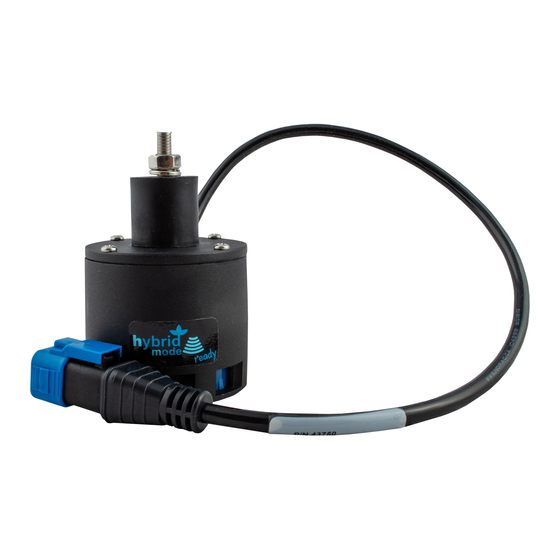
Kit Parts Kit Overview Figure 2: RG11 System Parts... - Page 8 Hydraulic Plumbing Figure 3: RG11 Hydraulic Plumbing...
- Page 9 CABLE UC5 NETWORK 14 AWG 5M 43220-01 CABLE UC5 NETWORK 14 AWG 1M 43210-15 CABLE UC5 NETWORK 18 AWG 15M 43230-04 CABLE UC5 VALVE 2PIN DT TO 2PIN DT 43710-AG UC5 CONTROLLER MODULE - AGCO 43720 UC5 VALVE MODULE 43741 UC5 ROLL SENSOR VER.
- Page 10 Item Part Number Name Quantity UC5-BC-RG11-INST MANUAL INSTALLATION UC5 ROGATOR PASSIVE ROLL (2012+) 5 HEIGHT SENSORS 106849 BUMPER RUBBER 106904 BOLT U 304SS .31-18 THD X 1.88 X 2.63 106906 NUT LOCK NYLON SS 3/8 IN 106905 BOLT CARRIAGE SS 3/8X1-1/4...
- Page 11 Hydraulic Fitting Kit Details (P/N: 44865-54) Item Part Number Name Quantity Picture 104586 TEE ADAPTER - 6FORXR 6MORT 104885 TEE ADAPTER - 8FORXR 8MORT 105327 MALE TO FEMALE ADAPTER - 12FORX 6MOR 106136 PLUG - 12MORP 44917 MALE ADAPTER - 6MB 6MOR 104369 PLUG - 6MBP 44928...
- Page 12 BRACKET MOUNTING LINEAR ROLL ROGATOR LT - LOWER Do not use high speed power tools/drills when installing hardware. The use of dielectric grease is not recommended on any NORAC electrical connections. To ensure all stainless steel hardware does not gall or seize apply a light coating of the supplied Permatex Anti-seize grease to all threaded parts upon installation.
-
Page 13: Pre-Install Checklist
Pre-Install Checklist The pre-install checklist is necessary to check the existing sprayer functionality before the installation. 1. Unfold the sprayer over a flat, unobstructed area (i.e. no power lines…etc.). 2. Ensure all boom-fold operations are functional (place a check mark in boxes below). 3. -
Page 14: Ultrasonic Sensor Installation
Ultrasonic Sensor Serial Number Arrangement When installing the UC5 sensors, start with the smallest serial number on the left-hand side, and proceed to the largest serial number on the right hand side. Each UC5 sensor has a serial number stamped on the sensor housing. - Page 15 Ultrasonic Sensor Mounting Guidelines The following guidelines will ensure optimal sensor performance and prevent sensor measurement error. These rules should be followed for both the wing sensors and the main lift (middle) sensor. 1. In its lowest position, the sensor must be 9 inches (23 cm) or more from the ground. 2.
- Page 16 Low Profile Bracket Mounting Guidelines 1. Minimize the distance between the bolts to prevent bending the bracket and prevent the bracket from loosening over time. 2. Ensure the bracket is mounted tight against the bottom of the boom, minimizing the distance between the boom structure and the angled flange.
- Page 17 Wing Sensor Installation 1. The sensor bracket should be oriented forward (ahead of the boom). 2. Typically, the best mounting location for the outer wing sensor brackets will be near the end of the boom tips, approximately two feet (60cm) from the end. Mount the bracket using the u-bolts (M08) and lock nuts (M09).
- Page 18 Figure 9: Inner Wing Sensor Bracket with Spacer (90’ and 100’ Booms Only)
- Page 19 Main Lift Sensor Installation 1. There are a variety of ways to mount the main lift bracket on most sprayers. The bracket should position the sensor approximately in the center of the sprayer, forward of the boom. An example of this mounting is illustrated in Figure 10. 2.
-
Page 20: Roll Sensor Installation
Roll Sensor Installation Bracket Assembly 1. Securely mount the roll sensors to the included roll sensor brackets using the #6 machine screws. Tighten screws to 10 in-lbs (1.1 Nm). 2. The orientation of the mounted roll sensor to the roll sensor bracket will depend on the bracket mounting. - Page 21 Roll Sensor Mounting Guidelines 1. When mounting the roll sensors, mount one to the boom frame and one to the chassis (non-pivoting portion of the sprayer). 2. Both roll sensor cables should be pointing towards the right-hand wing of the sprayer. 3.
-
Page 22: Module Installation
(Figure 15). 3. All cables that connect to the control module are located in the electrical box. 4. Connect the cable marked “NORAC C1” to the end of the control module with only one Deutsch connector. 5. Connect the cables marked “NORAC C2” and “NORAC C3” to the control module CANbus connectors. - Page 23 Figure 15: Control Module and Electrical Box Location...
- Page 24 Valve Module 1. Install the valve module (E02) to the top of the NORAC valve block. Orient the 6-pin Deutsch (CANbus) connectors towards the “P” and “T” ports with the label facing up. Output Number Normal Function Left Up Left Down...
- Page 25 Figure 18: Valve Module Bracket Installation 5. Connect one of the valve module CANbus connectors to the existing cable labeled “NORAC” running to the rear of the sprayer from the electrical box. Route cable C03 from the other CANbus connector to the 8-way coupler (E11).
-
Page 26: Hydraulic Installation
Component failure due to oil contamination is not covered under the NORAC UC5 system warranty. It is recommended that a qualified technician perform the hydraulic installation. - Page 27 Valve Block Mounting 1. A suitable mounting location for the valve block on the Rogator is illustrated in Figure 21. 2. Insert the threaded rod into the block and use a hex nut to hold the rod. The block holes are 3/8”...
- Page 28 Linear Damper Installation Before continuing, tilt both the left and right booms up to the top of their stroke to make it easier to rotate the boom. 1. Before installing the linear damper, the factory springs, dampers and rubber bumpers must be removed from the sprayer.
- Page 29 Figure 24: Small Tree - AGCO Factory Spring, Damper, and Rubber Bumper Location Figure 25: Linear Damper Mounting Location – Figure 26: Linear Damper Mounting Location – Small Tree with Factory Mounting Brackets Large Tree with Factory Mounting Brackets Figure 27: Linear Damper Mounting Location – Large Tree with Aftermarket Mounting Brackets...
- Page 30 4. Using the included 1 inch bolt, washers, and spacers, install the end of the linear damper with the hydraulic port onto the top mounting bracket. The spacers must be installed as shown. Flat Washer Flat Washer Thick Spacers Flat Washer Flat Washer Thick Spacer...
- Page 31 2. Disconnect the tank line at the Rogator valve block and insert the 8FORXR-8MORT tee (F03). 3. Connect the straight end of hose H05 to the tee and route to the NORAC valve block. 4. Disconnect the pressure line at the Rogator valve block and insert the 6FORXR-6MORT tee (F02).
-
Page 32: Connecting The Sensors To The Canbus
5. Connect cable C05 to the remaining connector on the 3-way coupler and route along the boom to the outer wing sensors. Figure 30: UC5 Module Locations and Cable Connections 6. At the sensor brackets, attach a 2-way coupler with terminator (E20) to the sprayer boom. -
Page 33: Software Setup
3. Turn on the power for the display terminal using the switch on the side. 4. The procedure for the installation of the UC5 Spray Height Control system is now complete. Begin the AUTOMATIC SYSTEM SETUP procedure as described in the UC5... -
Page 34: Cable Drawings
12 Cable Drawings 12.1 ITEM C03: 43220-05 - CABLE UC5 NETWORK 14 AWG - 5M 12.2 ITEM C04: 43220-01 - CABLE UC5 NETWORK 14 AWG - 1M... - Page 35 12.3 ITEM C05: 43210-15 - CABLE UC5 NETWORK 18 AWG - 15M 12.4 ITEM C10: 43230-04 – CABLE UC5 VALVE DT TO DT...
- Page 36 TOPCON Agriculture Canada 3702 Kinnear Place Saskatoon, SK S7P 0A6 TOPCON Agriculture Americas W5527 Hwy 106 Fort Atkinson, WI 53538 TOPCON Precision Agriculture Europe Avenida de la industria, 35, Tres Cantos, España Spain Support Phone: 888 979 9509 E-mail: tasupportn@topcon.com Web: www.norac.ca...
Need help?
Do you have a question about the UC5 and is the answer not in the manual?
Questions and answers