Norac UC5 Upgrade Manual
Spray height control system, john deere active roll with position sensors
Hide thumbs
Also See for UC5:
- Operator's manual (68 pages) ,
- Installation manual (50 pages) ,
- Instruction manual (35 pages)
Advertisement
Quick Links
Advertisement

Related Manuals for Norac UC5


Summary of Contents for Norac UC5
- Page 1 John Deere Active Roll with Position Sensors Upgrade Manual 5467BC-JD...
- Page 2 Reorder P/N: 5467BC-JD-INST Rev B (JD Active Roll with Position Sensor Upgrade) NOTICE: NORAC Systems International Inc. reserves the right to improve products and their specifications without notice and without the requirement to update products sold previously. Every effort has been made to ensure the accuracy of the information...
-
Page 3: Table Of Contents
Contents List of Parts ........................1 Position Sensor Installation ..................2 Roll Cylinder Installation .................... 5 Software Setup ......................8 System Maintenance ....................9 Cable Drawings ......................10 ... -
Page 4: List Of Parts
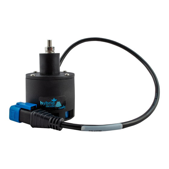
CABLE UC5 NETWORK 14 AWG 1M 45030 UC5 POSITION SENSOR NF W/O HARDWARE 43764 UC5 NETWORK COUPLER 2-WAY 44695-22 HYD CYLINDER AR 1.75IN W/INTERNAL SENSOR 5467BC-JD MANUAL INSTALLATION UC5 ACTIVE ROLL CONTROL W POSITION SENSOR - JD 106548 DRILL BIT 3/8" HSS STD JOBBER... -
Page 5: Position Sensor Installation
Position Sensor Installation 1. Remove the existing roll sensor, roll sensor bracket and target rods from the sprayer. When removing the roll sensor, leave the 2-way coupler and cabling in place as this will be used to connect the position sensor to the system. Remove Bracket and Sensor (leave cabling connected) - Page 6 4. Mount the brackets (B09) as shown in Figure 3, Figure 4 and Figure 5. Install two (2) cable ties per bracket. Figure 3: Bottom Bracket Mounting Figure 4: Top Bracket Mounting Figure 5: Bracket Mounting (Looking from the Rear) 5.
- Page 7 be 4” (100mm). The collar (Figure 6) clamps the sensor and prevents the rubber grommet from sitting on the bolt threads. Tighten the mounting hardware. 7. Connect the position sensor to the 2-way coupler where the roll sensor was connected. Centerline Mark 4”...
-
Page 8: Roll Cylinder Installation
Component failure due to oil contamination is not covered under the NORAC UC5 system warranty. It is recommended that a qualified technician perform the hydraulic installation. - Page 9 5. Install the cylinder (H75) into the lower mount so that the cylinder ports face the front of the sprayer. Ensure the pivot sleeve is installed into the cylinder. Install the bolt through the cylinder and sleeve and torque to 250 ft-lbs (339 Nm). Figure 9: Lower Bolt Installation 6.
- Page 10 10. Deburr the holes. Install the mounting bolts into the holes and snug. Drill the second set of holes and install the mounting bolts. Torque the bolts to 20 ft-lbs (27 Nm). Figure 12: Upper Pin Installed 11. In some cases, the bracket has failed at the weld shown in Figure 13. It is recommended that all sprayers with roll control add weld to the existing bracket to prevent failure.
-
Page 11: Software Setup
3. Turn on the power for the display terminal using the switch on the side. 4. The procedure for the installation of the UC5 Spray Height Control system is now complete. Begin the AUTOMATIC SYSTEM SETUP procedure as described in the UC5 Spray Height Control Operator’s Manual. -
Page 12: System Maintenance
System Maintenance For good performance in corners, when driving over terraces or through ditches at an angle, or in hard steer situations it is important to do the following: 1. The Teflon sliding pads on the boom must not grab in dynamic situations (corners, terraces etc). -
Page 13: Cable Drawings
Cable Drawings ITEM C04: 43220-01 - CABLE UC5 NETWORK 14 AWG – 1M... - Page 14 Canada NORAC Systems International Inc. Phone: (+1) 306 664 6711 Toll Free: 1 800 667 3921 Shipping Address: 3702 Kinnear Place Saskatoon, SK S7P 0A6 United States NORAC, Inc. Phone: (+1) 952 224 4142 Toll Free: 1 866 306 6722...
Need help?
Do you have a question about the UC5 and is the answer not in the manual?
Questions and answers