Norac UC5 Installation Manual
Spray height control system goldacres passive roll – g8
Hide thumbs
Also See for UC5:
- Operator's manual (68 pages) ,
- Installation manual (50 pages) ,
- Instruction manual (35 pages)
Table of Contents
Advertisement
Quick Links
Advertisement
Table of Contents

Related Manuals for Norac UC5


Summary of Contents for Norac UC5
- Page 1 Goldacres Passive Roll – G8 Installation Manual GA02...
- Page 2 Reorder P/N: UC5-BC-GA02-INST Rev B (Goldacres Passive Roll – G8) NOTICE: NORAC Systems International Inc. reserves the right to improve products and their specifications without notice and without the requirement to update products sold previously. Every effort has been made to ensure the accuracy of the information...
-
Page 3: Table Of Contents
Contents Introduction ........................ 1 Technical Specifications .................... 2 General UC5 System Layout ..................3 Kit Parts ........................4 Pre-Install Checklist ....................8 Ultrasonic Sensor Installation .................. 9 Position Sensor Installation ..................14 ... -
Page 4: Introduction
Introduction Congratulations on your purchase of the NORAC UC5 Spray Height Control System. This system is manufactured with top quality components and is engineered using the latest technology to provide operating reliability unmatched for years to come. When properly used the system can provide protection from sprayer boom damage, improve sprayer efficiency, and ensure chemicals are applied correctly. -
Page 5: Technical Specifications
Technical Specifications CAN ICES-3(A)/NMB-3(A) This device complies with part 15 of the FCC Rules. Operation is subject to the following two conditions: (1) This device may not cause harmful interference, and (2) this device must accept any interference received, including interference that may cause undesired operation. This equipment has been tested and found to comply with the limits for a Class A digital device, pursuant to part 15 of the FCC Rules. -
Page 6: General Uc5 System Layout
General UC5 System Layout Figure 1 illustrates the general layout of the UC5 system components: Figure 1: General UC5 System Layout... -
Page 7: Kit Parts
Kit Parts Kit Overview Figure 2: GA02 System Parts... - Page 8 Hydraulic Plumbing Figure 3: GA02 Hydraulic Plumbing NOTE: Only fittings F07 and F08 are included with this kit. All other hydraulic hoses and fittings are supplied by Goldacres.
- Page 9 CABLE UC5 NETWORK 14 AWG 10M 43220-01 CABLE UC5 NETWORK 14 AWG 1M 43230-04 CABLE UC5 VALVE 2PIN DT TO 2PIN DT 43240-44 CABLE UC5 INTERFACE TILT GP (WEATHERPACK - SINGLE) 43240-45 CABLE UC5 INTERFACE MAIN GP (WEATHERPACK - SINGLE)
- Page 10 Not all fittings are used for this installation. Do not use high speed power tools/drills when installing hardware. The use of dielectric grease is not recommended on any NORAC electrical connections. To ensure all stainless steel hardware does not gall or seize apply a light coating of the supplied Permatex Anti-seize grease to all threaded parts upon installation.
-
Page 11: Pre-Install Checklist
Pre-Install Checklist The pre-install checklist is necessary to check the existing sprayer functionality before the installation. 1. Unfold the sprayer over a flat, unobstructed area (i.e. no power lines…etc.). 2. Ensure all boom-fold operations are functional (place a check mark in boxes below). 3. -
Page 12: Ultrasonic Sensor Installation
Ultrasonic Sensor Serial Number Arrangement When installing the UC5 sensors, start with the smallest serial number on the left-hand side, and proceed to the largest serial number on the right hand side. Each UC5 sensor has a serial number stamped on the sensor housing. - Page 13 Ultrasonic Wing Sensor Mounting Guidelines The following guidelines will ensure optimal sensor performance and prevent sensor measurement error. These rules should be followed for both the wing sensors and the main lift (middle) sensor. 1. In its lowest position, the sensor must be 9 inches (23 cm) or more from the ground. 2.
- Page 14 Low Profile Bracket Mounting Guidelines 1. Minimize the distance between the bolts to prevent bending the bracket and prevent the bracket from loosening over time. 2. Ensure the bracket is mounted tight against the bottom of the boom, minimizing the distance between the boom structure and the angled flange.
- Page 15 4. Mount the NORAC UC5 ultrasonic sensor into the sensor bracket and run the sensor cable either through hole in the back or through the side cut-out and behind the bracket.
- Page 16 Ultrasonic Main Lift Sensor Mounting Guidelines The following guidelines will ensure optimal sensor performance and prevent sensor measurement error. 1. In its lowest position, the sensor must be 9 inches (23 cm) or more from the ground. 2. The centerline of the acoustic cone should be approximately vertical at normal operating heights.
-
Page 17: Position Sensor Installation
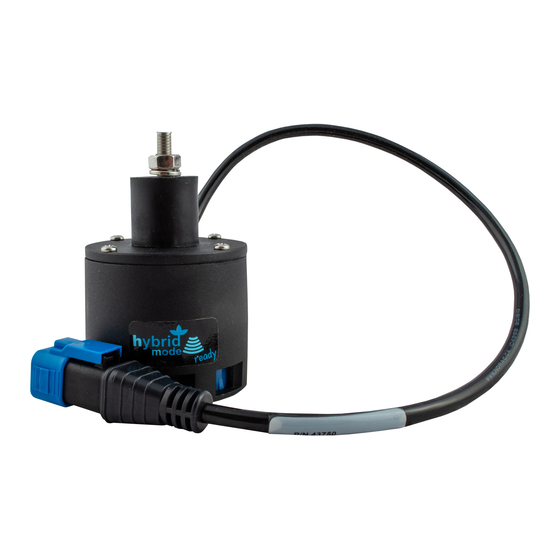
Position Sensor Installation 1. The position sensor (E06) should be mounted such that the largest amount of travel of the sensor can be utilized without exceeding the travel limit. The sensor install length is 17” (430mm) center to center with ±3.5” (±90mm) travel recommended. The travel limit is indicated by red bands on the position sensor. -
Page 18: Module Installation
Module Installation An optional module mounting bracket kit is available for purchase from NORAC. mounting brackets are compatible with control modules and input modules. One kit is needed per module. Item Part Number Name Quantity 43708 UC5 MOUNTING BRACKET KIT (CONTROL AND INPUT MODULES) Control Module 1. - Page 19 Valve Module 1. Install the valve module (E02) to the top of the NORAC valve block. Orient the 6-pin Deutsch (CANbus) connectors towards the “P” and “T” ports with the label facing up. Output Number Normal Function Left Up Left Down...
- Page 20 Figure 16: Valve Module Bracket Installation 5. Connect the valve module CANbus to cable C01 from the control module. Route cable C02 from the other CANbus connector to the input module. 6. With the valve module securely mounted to the valve block, connect the valve cables (C10), to the valve coils.
- Page 21 Input Module 1. Install the input module (E03) on the boom near the sprayer valve block. Secure it to the boom using cable ties or optional brackets. 2. Connect the CANbus cable (C02) from the valve module to the input module. Connect cable C02 to the other CANbus connector and route to the 8-way coupler.
-
Page 22: Connecting The Sensors To The Canbus
Connecting the Sensors to the CANbus 1. Fasten the 8-way coupler to the boom with cable ties. 2. Connect cable C02 from the input module to the 8-way coupler (E11). 3. Connect the position sensor to the 8-way coupler. 4. Connect the main lift sensor to the 8-way coupler using cable C02 and a 2-way coupler (E12). -
Page 23: Hydraulic Installation
Component failure due to oil contamination is not covered under the NORAC UC5 system warranty. It is recommended that a qualified technician perform the hydraulic installation. - Page 24 tightened to 35-40 in-lbs to ensure a tight seal. Reinstall the plug and tighten to 35-40 in- lbs. Figure 20: Load Sense Bleed Orifice Location on Top of Block...
- Page 25 10.2 Valve Block Mounting 1. Mount the valve block on the sprayer near the existing valve block. 2. Use the supplied valve bracket to install the valve block. 3. Insert the threaded rod into the block and use a hex nut to hold the rod. The block holes are 3/8”...
- Page 26 3. Connect four hydraulic hoses from the free ends of the tees to the NORAC valve block. The raise lines must be connected to the “B” ports and the lower lines must be connected to the “A”...
-
Page 27: Software Setup
3. Turn on the power for the display terminal using the switch on the side. 4. The procedure for the installation of the UC5 Spray Height Control system is now complete. Begin the AUTOMATIC SYSTEM SETUP procedure as described in the UC5... -
Page 28: Cable Drawings
12 Cable Drawings 12.1 ITEM C01: 43220-10 - CABLE UC5 NETWORK 14 AWG - 10M 12.2 ITEM C02: 43220-01 - CABLE UC5 NETWORK 14 AWG - 1M... - Page 29 12.3 ITEM C10: 43230-04 – CABLE UC5 VALVE DT TO DT...
- Page 30 12.4 ITEM C20: 43240-44 – CABLE UC5 INTERFACE TILT GP (WEATHERPACK - SINGLE)
- Page 31 12.5 ITEM C21: 43240-45 – CABLE UC5 INTERFACE MAIN GP (WEATHERPACK - SINGLE)
- Page 32 12.6 ITEM C30: 43250-06 – CABLE BATTERY PIGTAIL FUSED...
-
Page 33: Appendix A: Severe Terrain Option
5. Mount the NORAC ultrasonic sensor into the sensor bracket and run the sensor cable either through hole in the back or through the side cut-out and behind the bracket. Ensure the cable is clear of moving parts and will not be damaged during folding. - Page 34 Figure 22: Sensor Serial Number Arrangement (Severe Terrain Sensors shown in Black)
- Page 35 TOPCON Agriculture Canada 3702 Kinnear Place Saskatoon, SK S7P 0A6 TOPCON Agriculture Americas W5527 Hwy 106 Fort Atkinson, WI 53538 TOPCON Precision Agriculture Europe Avenida de la industria, 35, Tres Cantos, España Spain Support Phone: 888 979 9509 E-mail: tasupportn@topcon.com Web: www.norac.ca...
Need help?
Do you have a question about the UC5 and is the answer not in the manual?
Questions and answers