Norac UC5 Installation Manual
Spray height controller, generic unit (fixed geometry)
Hide thumbs
Also See for UC5:
- Operator's manual (68 pages) ,
- Installation manual (50 pages) ,
- Instruction manual (35 pages)
Table of Contents
Advertisement
Quick Links
Advertisement
Table of Contents

Subscribe to Our Youtube Channel
Related Manuals for Norac UC5


Summary of Contents for Norac UC5
- Page 1 Spray Height Controller Generic Unit (Fixed Geometry) Installation Manual GN02...
- Page 2 Reorder P/N: UC5-BC-GN02-INST Rev A (Generic Unit Fixed Geometry) NOTICE: NORAC Systems International Inc. reserves the right to improve products and their specifications without notice and without the requirement to update products sold previously. Every effort has been made to ensure the accuracy of the information contained in this...
-
Page 3: Table Of Contents
Contents Introduction......................1 General UC5 System Layout .................. 2 Kit Parts........................3 Pre-Install Checklist ....................5 Ultrasonic Sensor Installation................. 6 Module Installation....................10 Connecting the Sensors to the CAN-Bus ............. 13 Software Setup ....................... 14 Cable Drawings ...................... 15... -
Page 4: Introduction
1 Introduction Congratulations on your purchase of the NORAC UC5 Spray Height Controller. This system is manufactured with top quality components and is engineered using the latest technology to provide operating reliability unmatched for years to come. When properly used the system can provide protection from sprayer boom damage, improve sprayer efficiency, and ensure chemicals are applied correctly. -
Page 5: General Uc5 System Layout
2 General UC5 System Layout Figure 1 and Figure 2 illustrate the general layout of the UC5 system components: Figure 1: General UC5 System Layout (Self Propel Type) Figure 2: General UC5 System Layout (Pull Type) -
Page 6: Kit Parts
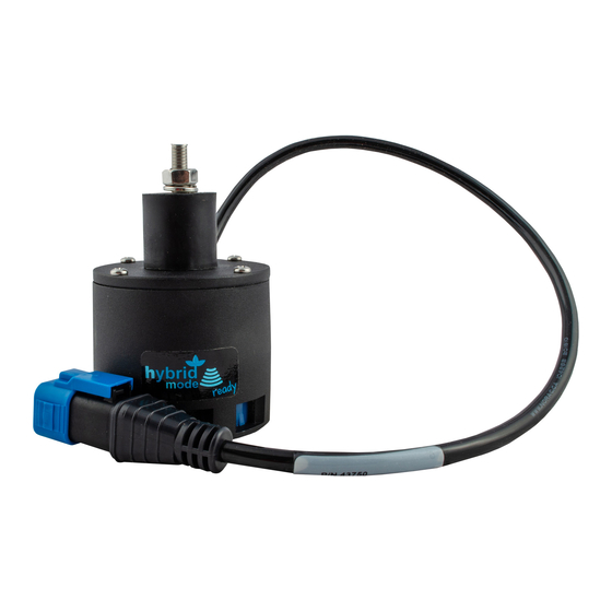
3 Kit Parts The following diagrams illustrate the GN02 kit specific parts of the NORAC UC5 system. Interface cables (C21) and power cables (C30) are shown in this manual and may not be included. Cables are available separately from NORAC. Please refer to the UC5 Generic Cable Ordering Guide (P/N: UC5-BC-CABLE-GUIDE), for cable ordering information. - Page 7 UC5 CONTROLLER MODULE 43732 UC5 INPUT MODULE PASS THRU 43750 UC5 ULTRASONIC SENSOR 43760 UC5 NETWORK COUPLER 3-WAY 43780 UC5 NETWORK TERMINATOR PLUG UC5-BC-MANUAL MANUAL OPERATORS UC5 UC5-BC-GN02-INST MANUAL INSTALLATION UC5 GENERIC UNIT (FIXED BOOM) 106035 UC5 NETWORK 12 PIN PLUG (A-KEY)
-
Page 8: Pre-Install Checklist
4 Pre-Install Checklist The pre-install checklist is necessary to check the existing sprayer functionality before the installation. 1. Unfold the sprayer over a flat, unobstructed area (i.e. no power lines…etc.). 2. Ensure all boom-fold operations are functional (place a check mark in boxes below). 3. -
Page 9: Ultrasonic Sensor Installation
5 Ultrasonic Sensor Installation Bracket Assembly Assemble the breakaway sensor bracket as illustrated in Figure 5, following the instructions below. Figure 5: Breakaway Bracket Assembly 1. Compress the spring and insert it together with the collar into the base. 2. Slide the tube through the assembled part. 3. - Page 10 Ultrasonic Sensor Serial Number Arrangement When installing the UC5 sensors, start with the smallest serial number on the left-hand side, and proceed to the largest serial number on the right hand side. Each UC5 sensor has a serial number stamped on the sensor housing.
- Page 11 Ultrasonic Sensor Mounting Guidelines The following guidelines will ensure optimal sensor performance and prevent sensor measurement error. These rules should be followed for both the wing sensors and the main lift (middle) sensor. 1. In its lowest position, the sensor must be 9 inches (23 cm) or more from the ground (A). 2.
- Page 12 If the sensor is mounted to this portion of the boom, the system will force the boom downwards towards the ground as the boom folds backwards. 4. Mount the NORAC UC5 ultrasonic sensor into the sensor bracket and run the sensor cable through the sensor tube.
-
Page 13: Module Installation
6 Module Installation Control Module: Self Propel Sprayer 1. Refer to Figure 1 and Figure 9. 2. Securely mount the control module (E01) inside the sprayer cab, using screws or cable ties. 3. Connect the display terminal to the control module using the existing display cable. This cable must be connected to the end of the control module with only one Deutsch connector. - Page 14 Control Module: Pull Type Sprayer 1. Refer to Figure 2 and Figure 10. 2. Securely mount the control module (E01) near the hitch of the sprayer, near the display terminal connections. 3. Connect the display terminal to the control module using the existing display CAN-bus cable. This cable must be connected to the end of the control module with only one Deutsch connector.
- Page 15 Input Module 1. Install the input module (E03) on the boom near the sprayer valve block. Secure it to the boom with cable ties. 2. Connect the free end of the CAN-bus cable (C01) from the control module to the input module.
-
Page 16: Connecting The Sensors To The Can-Bus
Follow existing cables and hoses to be sure the cable will not be pinched or stretched. Figure 12: UC5 Module Locations and Cable Connections 4. At the sensor brackets, attach a 3-way coupler (E10) to the sprayer boom. Plug the sensor and the CAN-bus cable into the 3-way coupler. -
Page 17: Software Setup
Begin the AUTOMATIC SYSTEM SETUP procedure as described in the UC5 Spray Height Control Operator’s Manual. 5. For optimal performance of the UC5 system, there should be very little play at the hitch clevis. The addition of polymer washers can help tighten up this connection (Figure 13). -
Page 18: Cable Drawings
9 Cable Drawings ITEM C01: 43220-10a - CABLE UC5 NETWORK 14 AWG - 10M ITEM C03: 43210-01a - CABLE UC5 NETWORK 18 AWG - 1M... - Page 19 ITEM C05: 43210-20a - CABLE UC5 NETWORK 18 AWG - 20M...
- Page 20 Canada NORAC Systems International Inc. Phone: (+1) 306 664 6711 Toll Free: 1 800 667 3921 Shipping Address: 3702 Kinnear Place Saskatoon, SK S7P 0A6 United States NORAC, Inc. Phone: (+1) 763 786 3080 Toll Free: 1 866 306 6722...
Need help?
Do you have a question about the UC5 and is the answer not in the manual?
Questions and answers