
Related Manuals for CHIEF Thinstall MSTU


Summary of Contents for CHIEF Thinstall MSTU
- Page 1 I N S T A L L A T I O N I N S T R U C T I O N S Thinstall™ Medium Static Universal Mount MSTU...
-
Page 2: Installation Instructions
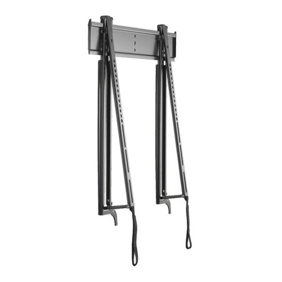
Never operate this mounting system if it is WARNING: Chief® and Thinstall™ are registered trademarks of Milestone damaged. Return the mounting system to a service center for AV Technologies. All rights reserved. examination and repair. - Page 3 Installation Instructions MSTU DIMENSIONS 1.44 27.81 1.58 MA X 23.62 [600] MIN 3.94 [100] 4X .29 2.47 16.00 15.75 20.88 9° C A BLE AC C ESS C A BLE STA ND RELEA SE STRA PS A NG LE INT ERFA C E LO C KING SW IT C H DIMENSIONS: [MILLIMETERS]...
- Page 4 MSTU Installation Instructions LEGEND Tighten Fastener Pencil Mark Apretar elemento de fijación Marcar con lápiz Befestigungsteil festziehen Stiftmarkierung Apertar fixador Marcar com lápis Serrare il fissaggio Segno a matita Bevestiging vastdraaien Potloodmerkteken Serrez les fixations Marquage au crayon Measure Drill Hole Medir Perforar Messen...
-
Page 5: Tools Required For Installation
Installation Instructions MSTU TOOLS REQUIRED FOR INSTALLATION M2.5 (included) 3/16" (4.8mm) M3 (included) M4 (included) 5/16" (7.9mm) M4 (included) M5 (included) PARTS A (1) B (2) [Wall plate] C (1) [Upright] E (4) D (4) G (4) F (4) H (4) J (4) M4 x 12 M5 x 12... -
Page 6: Assembly And Installation
MSTU Installation Instructions Install four anchors (AA) into pilot holes drilled in Step 2. Assembly And Installation Use a hammer to tap anchors into holes. (See Figure 3) Wall Plate Installation Using Wood Studs Install four connector screws (D) through wall plate holes and into anchors. - Page 7 Installation Instructions MSTU (E - Q) x 4 (R) x 4 (if necessary) (S or T) x 4 (if necessary) Flag in open position (B) x 2 (U or V) x 4 (if necessary) Figure 4 Install four button head cap screws (E - Q) through required Make sure locking flags are in the open position before NOTE: washers (R) and shoulder washers (S or T), interface...
- Page 8 MSTU Installation Instructions Slowly guide hooks on top of interface brackets on top of Slowly pull bottom of display away from wall until kickstand wall plate in desired mounting location. (See Figure 5) fully reaches its down position. (See Figure 6) Slowly swing display toward wall.
-
Page 9: Cable Management
NOTE: the back may require 90-degree cable connectors. features a kickstand to allow access without having to Chief offers in-wall accessories that can assist with remove display from the wall. recessing cables and connections. Ensure kickstand is firmly in down position. - Page 10 MSTU Installation Instructions...
- Page 11 Installation Instructions MSTU...
- Page 12 P 800.582.6480 / 952.225.6000 F 877.894.6918 / 952.894.6918 A Franklinstraat 14, 6003 DK Weert, Netherlands Europe Chief, a products division of P +31 (0) 495 580 852 Milestone AV Technologies F +31 (0) 495 580 845 A Office No. 1 on 12/F, Shatin Galleria...
Need help?
Do you have a question about the Thinstall MSTU and is the answer not in the manual?
Questions and answers