Table of Contents
Advertisement
Quick Links
I N S T A L L A T I O N I N S T R U C T I O N S
Instrucciones de instalación
Installationsanleitung
Instruções de Instalação
Istruzioni di installazione
Installatie-instructies
Instructions d´installation
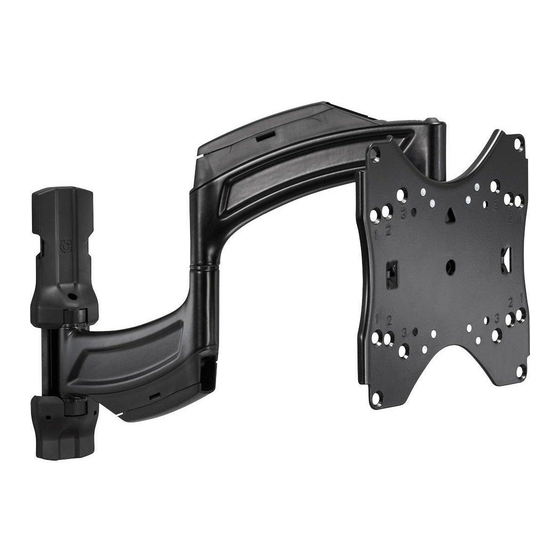
Medium Dual Swing Arm
Spanish Product Description
German Product Description
Portuguese Product Description
Italian Product Description
Dutch Product Description
French Product Description
TS218SU
Advertisement
Table of Contents

Related Manuals for CHIEF TS218SU


Summary of Contents for CHIEF TS218SU
- Page 1 I N S T A L L A T I O N I N S T R U C T I O N S Instrucciones de instalación Istruzioni di installazione Installationsanleitung Installatie-instructies Instruções de Instalação Instructions d´installation Medium Dual Swing Arm Spanish Product Description German Product Description Portuguese Product Description Italian Product Description Dutch Product Description French Product Description TS218SU...
-
Page 2: Important Warnings And Cautions
Chief® is a registered trademark of Milestone AV Technologies. IMPORTANT ! : The TS218SU mount is designed to be All rights reserved. -
Page 3: Installation Instructions
Installation Instructions TS218SU DIMENSIONS 2.65 67.3 PAN MOTION 90 LEFT/RIGHT 18.0 456.2 MAXIMUM 12° 1.50 EXTENSION 38.1 TILT MINIMUM FROM WALL 1.00 25.4 SCREEN CENTER TO TOP 2.58 SCREEN CENTER LAG BOLT 65.5 8.12 206.1 .265 6.73 - .50" [12.7] UP/DOWN HEIGHT ADJUSTMENT... - Page 4 TS218SU Installation Instructions LEGEND Tighten Fastener Pencil Mark Apretar elemento de fijación Marcar con lápiz Befestigungsteil festziehen Stiftmarkierung Apertar fixador Marcar com lápis Serrare il fissaggio Segno a matita Bevestiging vastdraaien Potloodmerkteken Serrez les fixations Marquage au crayon Loosen Fastener Drill Hole Aflojar elemento de fijación...
-
Page 5: Tools Required For Installation
Installation Instructions TS218SU TOOLS REQUIRED FOR INSTALLATION concrete only 1/8" - wood studs 7/16" (11.1mm) 8mm - concrete PARTS "A" A2 (4) A3 (4) A1 (4) M4x16mm M4x25mm M4x12mm H (1) "B" B1 (4) B2 (4) B3 (4) [faceplate] J (1) -
Page 6: Assembly And Installation
(J) is level when mounted to the wall! IMPORTANT ! : The TS218SU mount is designed to be mounted to a 2" x 4" wood studs (16" on center) wall. Drill one 1/8" hole at location marked in Step 2. (See Figure 1/8"... - Page 7 INSTALLING THE TS218SU INTO UNDERRATED OR DAMAGED CONCRETE CAN LEAD TO SERIOUS INJURY OR DAMAGE TO PRODUCT! Never install the TS218SU into cracked, chipped or flaking concrete. Determine mounting location. Measure 1" above desired center line and mark a hole at desired mounting location.
-
Page 8: Display Installation
TS218SU Installation Instructions Display Installation (configuration 2 shown) Install Interface Brackets to Faceplate (if necessary) IMPORTANT ! : If the displays hole pattern size is 100mm x 100mm, 200mm x 100mm or 200mm x 200mm, the display can be mounted directly to the faceplate and... - Page 9 Installation Instructions TS218SU Attach Faceplate to Display Using Interface Brackets (configuration 2 shown) Lay display face down on protective surface. (D) x4 (A-C) x4 or (E1) or (E3) x 4 CAUTION: Using screws of improper diameter may damage your display! Proper screws will easily thread into display mounting holes.
- Page 10 TS218SU Installation Instructions Attach Faceplate to Display Without Interface Use selected screws and spacers to connect interface brackets to back of display. (See Figure 11) Brackets (100x100 or 200x200 or 100x200 hole patterns) (200x200 configuration shown) Lay display face down on protective surface.
- Page 11 Installation Instructions TS218SU (M) x 2 (N) x 2 pitch bracket Figure 12 Install Display to Main Assembly Wall Cover Installation WARNING: Exceeding the weight capacity can result in CAUTION: Wall covers are fragile and may be damaged or serious personal injury or damage to equipment! It is the broken if installed with excessive force! Use caution when installer’s responsibility to make sure the combined weight of...
-
Page 12: Cable Management
Cable Management Height Adjustment Make all cable connections to display. The TS218SU may be adjusted 1/2" up or down after installation to the wall. Open cable management covers on upper and lower swing arms by unhinging center tabs and lifting covers to the open Remove display from main assembly. -
Page 13: Roll Adjustment
Installation Instructions TS218SU Roll Adjustment Arm Tension Adjustment Use 3/16" hex key (T) to adjust arm tension at any of the NOTE: If flange nuts (N) were not fully tightened when display three tension adjustment points. (See Figure 19) and (See... - Page 14 TS218SU Installation Instructions...
- Page 15 Installation Instructions TS218SU...
- Page 16 Europe A Franklinstraat 14, 6003 DK Weert, Netherlands P +31 (0) 495 580 852 F +31 (0) 495 580 845 Chief Manufacturing, a products division Asia Pacific A Office No. 1 on 12/F, Shatin Galleria of Milestone AV Technologies 18-24 Shan Mei Street...
Need help?
Do you have a question about the TS218SU and is the answer not in the manual?
Questions and answers